This project consists of two microcontrollers working together, an ESP8222 (lock) and an Attiny45 (key). The general idea is that the Key contains a secrete code that must be communicated with the lock in order for the lock to perform an action. This type of lock and key incorporates multiple lock and key concepts; you must physically have the key (like a normal door lock and key), the key must be placed on (in) the lock in the correct direction (like a normal door lock and key, the teeth must align with the tumblers), you must know the activation process (idk an example of this in the wild, maybe a kill switch in a car?), the key must issue the correct code combination (like a combo lock). This introduces so much complication that picking the lock would be extremely hard, it would be easier to hack the network communication at that point. Additional images, video, and schematics at the bottom.
Design:
I thought pogo pins were aesthetically pleasing and fun to use so I decided to use them as the contacts for power and data lines between the lock and key. The key must be placed on top of the pogo pins to trigger the process. Both parts have 3D printed cases to house all the electronics. The lock will sit on a desk or anywhere and be attached to power. The key is a floating piece that you can take anywhere.
Power:
The lock will be powered by micro USB and then provide power to all components via 3.3V regulator. Since this device works over wifi, it can be plugged in anywhere your wifi single can reach, it's not computer dependant. As mentioned before, the pogo pins will provide power to the Key once placed onto the lock.
Communication:
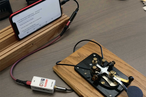
The device is using I2C to communicate between the attiny and esp8266 to establish a handshake. The esp will then use secure mqtt or https to trigger the action such as unlocking a computer. The system being unlocked such as a computer must be subscribed to the MQTT topic and begin its own process once triggered. Here is a breakdown of the communication flow. Key sends reset to esp via physical switch > esp boots and connects to wifi, builds the i2c bus then requests data from attiny > attiny sends data over i2c to esp > esp verifies data, if it's correct it publishes to an mqtt broker then goes back to sleep > mqtt broker sends a message to all subscribers > computer processes script to unlock itself.
Code/Programming Details:
I wanted this device to be very easily adaptable to other systems. I configured the ESP with OTA from the Arduino examples so I can upload new code to the ESP should I need to. The ESP does utilize deep sleep after it runs one cycle but I scheduled a 15 seconds loop that can handle OTA requests before it goes into an indefinite sleep. Unfortunately, there is no easy way to reprogram the Attiny with a new code except a custom pogo pin type jig to sit on top of it and reprogram it. I plan on building this jig later on down the road unless somebody knows how to utilize the ESP8266 as a AVR programmer (comments/suggestions welcome)!!!
Security:
Full warning, I'm not a security expert, I don't know how easy it would be to hack this Lock and Key. As far as i see it, there might be multiple vulnerabilities. The two devices talk over I2C which I don't know if that could be brute-forced through the lock, it would be very time consuming considering the lock only requests the data once then goes to sleep and must be woken up again. The Lock does connect to the wifi, I'm not sure how vulnerable the TCP/IP stack is on these ESP devices but that's another avenue. The ESP also uses MQTT but requires authentication and uses SSL and furthermore the ESP also sends a custom code block with its message, which might be a little more difficult to crack, you would have to auth to my MQTT broker and publish a message to the correct topic WITH the special code block. The ESP utilizes OTA with a password,...
Read more »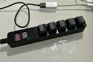
 Matt Perkins
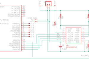
 W. Taylor
 Matthew Sparks