 Phil Malone
After toying with a wireless joystick interface, and several wired joysticks, I decided that I needed to provide a standardized plug-in joystick port on the Hoverboard.
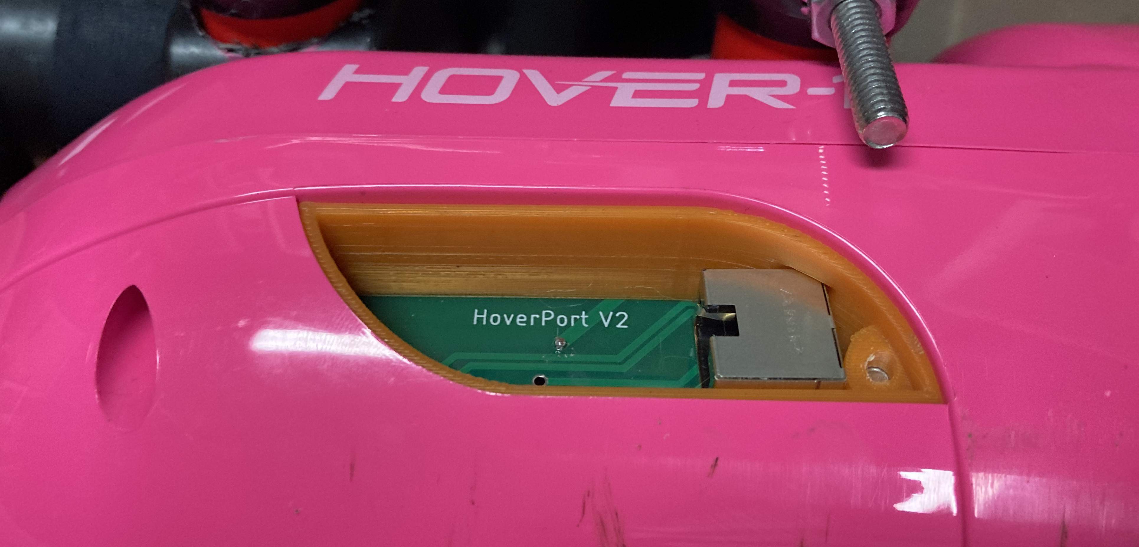
My final decision was to convert one of the existing decorative LED housings (that just lit up) into a Joystick port that uses an RJ45 connector to provide 5V power, Serial data and a remote on/off switch.
The LED display has a small PCB and a plastic housing that conformed to the shape of the Hoverboard.
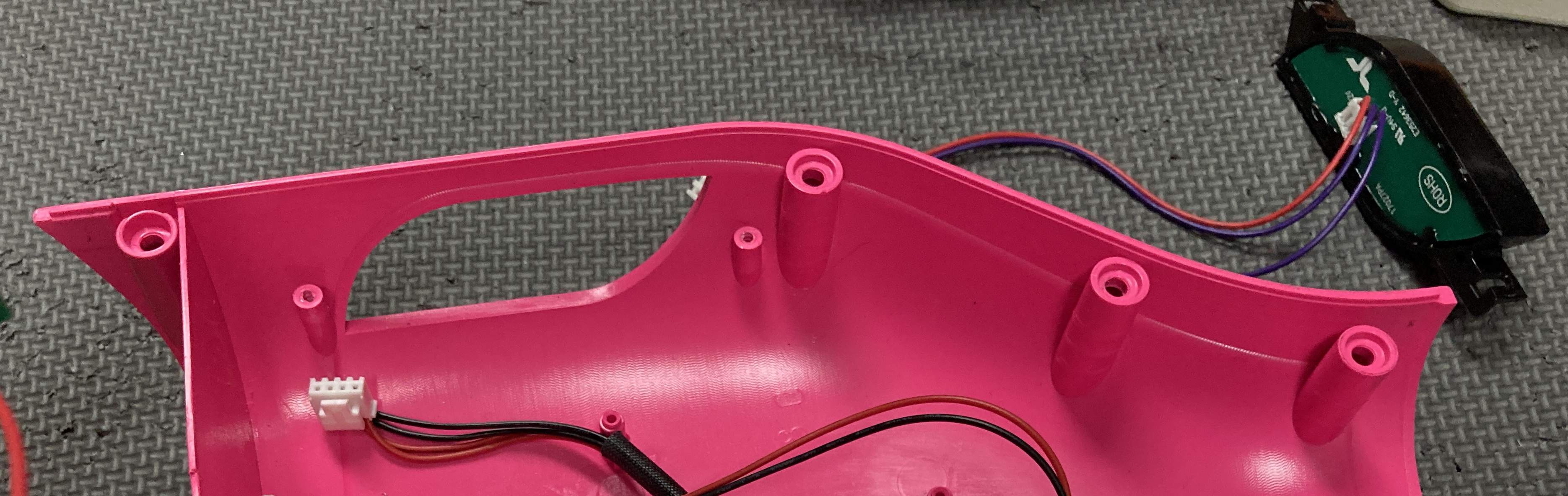
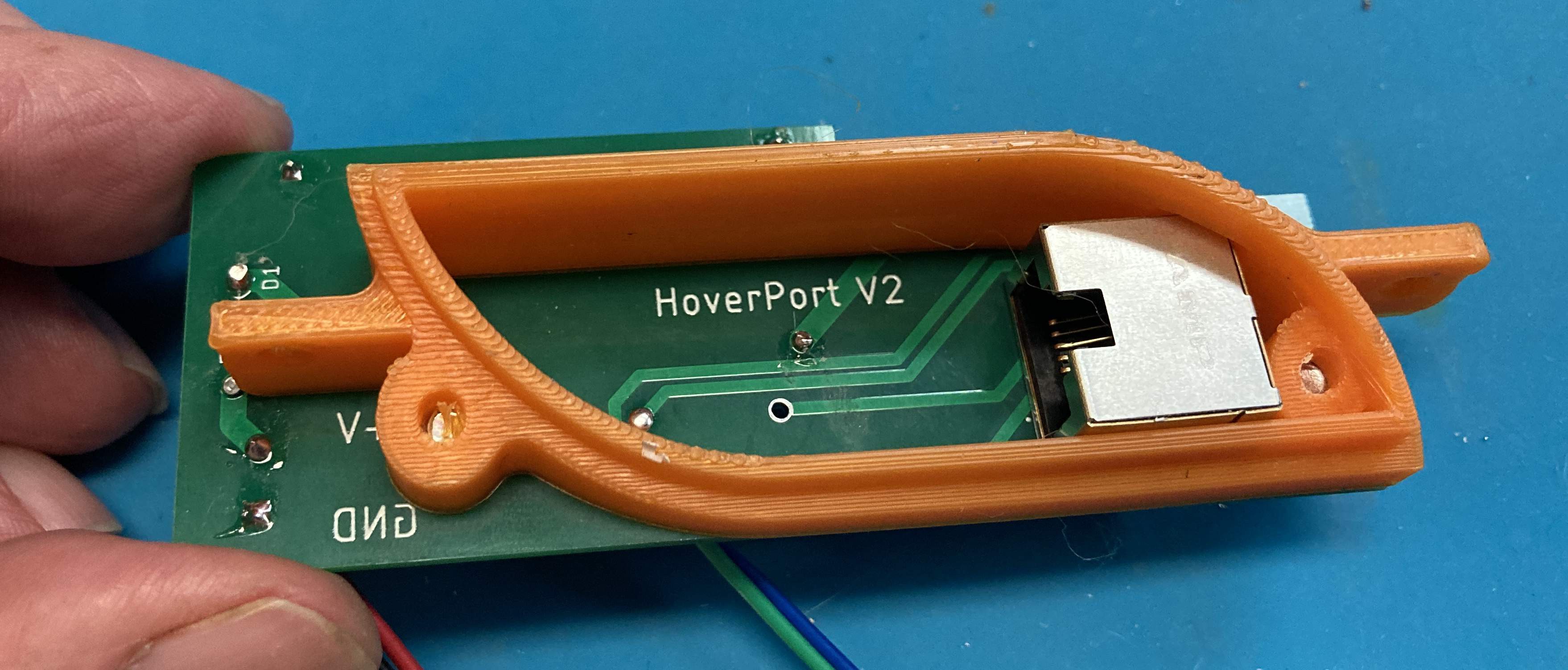
After much measuring and guesswork regarding curved surfaces, I created a 3D model using OnShape, and was able to print a replacement plastic piece that bolted to the Hoverboard's internal mounting points.
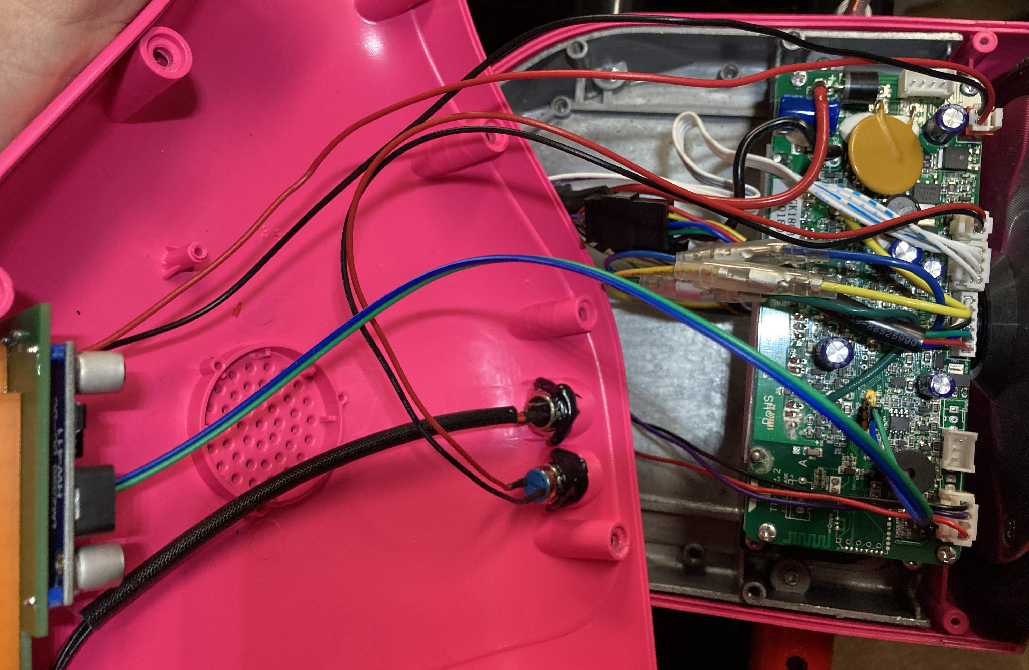
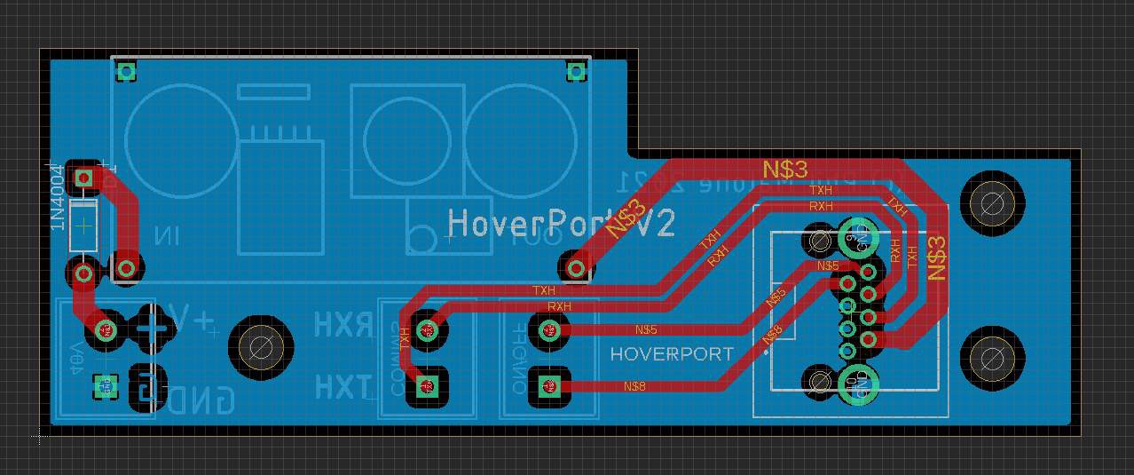
I designed a small PCB that allowed me to add a a 40-5V converter, and the RJ45 Socket. This board connects to the Hoverboard controller in three places. It plugs into two existing connectors and is also wired to an unused COMM debug port (soldering required) .
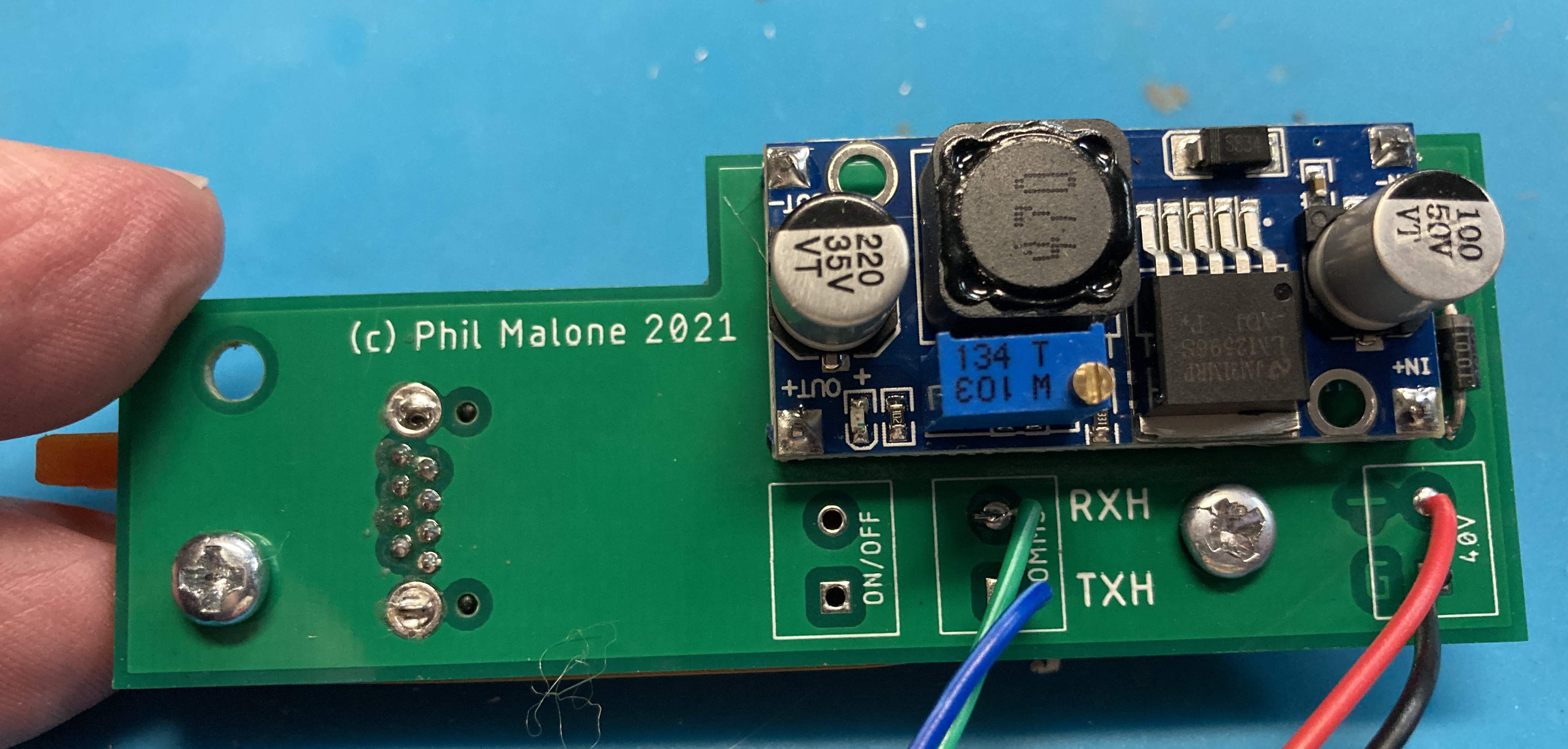
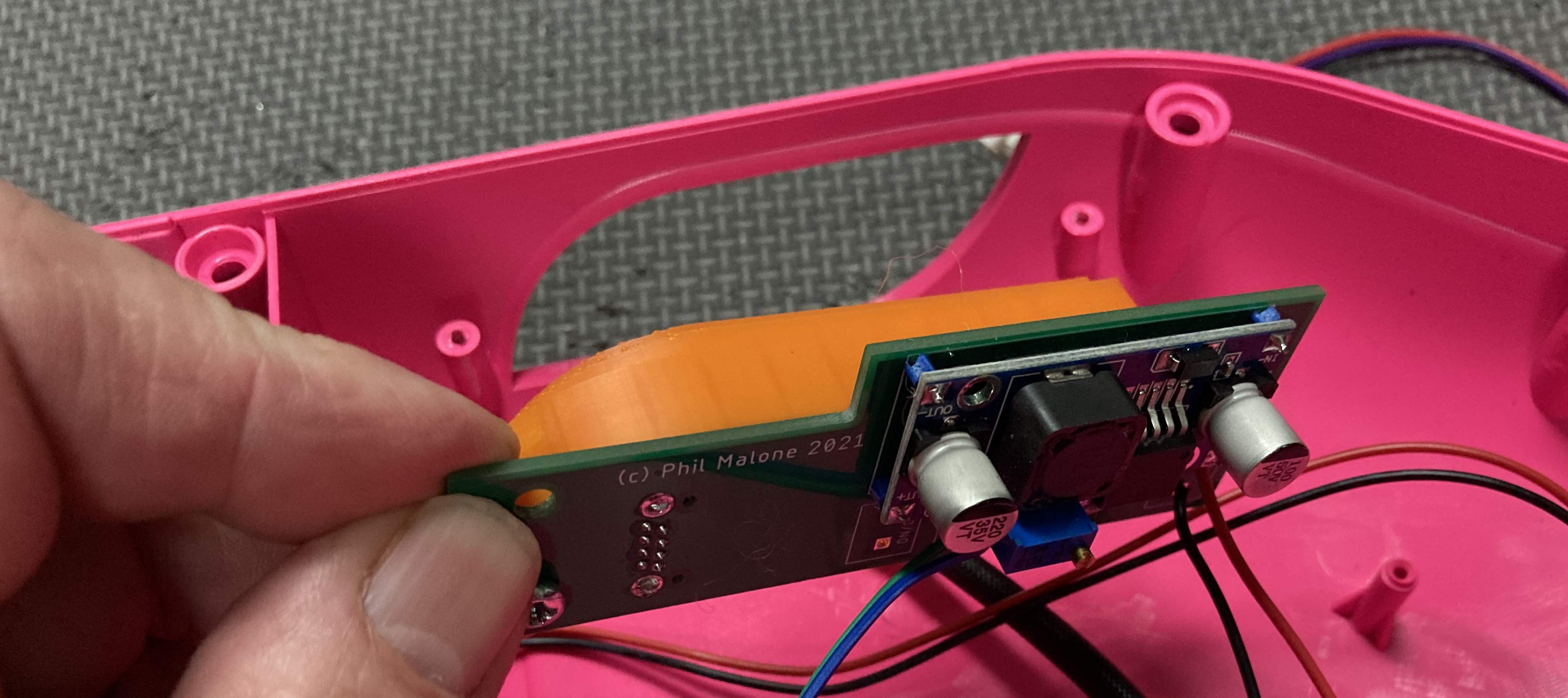
The Voltage converter used on this interface is a low cost Buck Converter, able to convert the 40V Battery Voltage to anywhere from 1.5 to 35V. I adjusted the output to 5.0V. I chose this voltage because most of the processors I might choose to use on a joystick are able to operate at 5V, with their own 5-3.3V regulators.
Since the RJ45 connector was mounted flush on the PCB, it was important to choose a connector that had the clip/release on the top of the connector (less common), so it could be manually released.
The PCB was manufactured by PCBWay, my favorite PCB supplier.
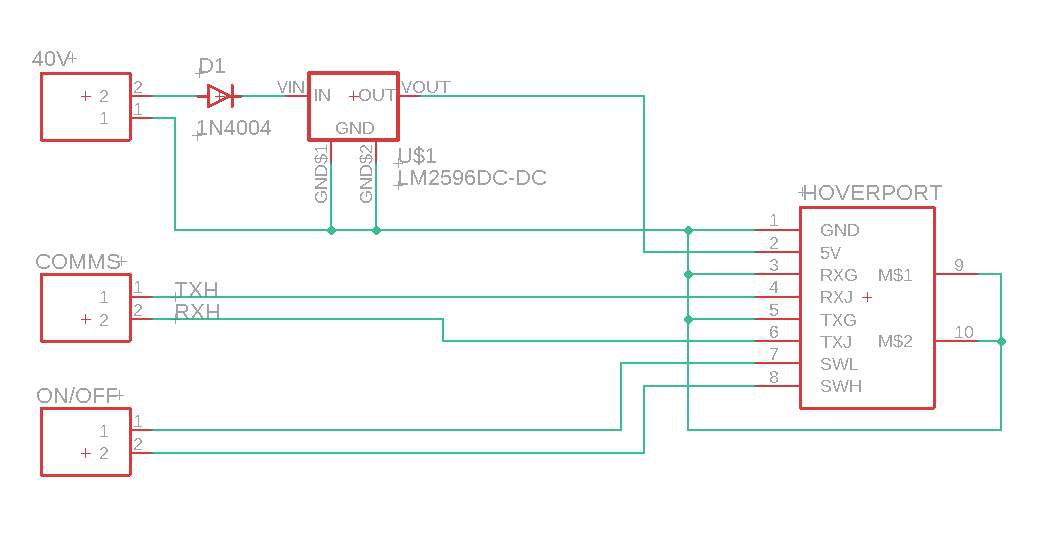
Note the series diode that is in-line with the 40V input. There is nothing worse than accidentally connecting a power supply input and getting the polarity reversed by mistake. The buck converter PCB warns against it, so I assume it will let the Magic Blue Smoke out. This 10c component will save me from a LOT of potential grief.
The two wires that would normally go to the Hoverboard power button just get passed through to the Joystick. Closing this circuit momentarily will power up the Hoverboard and cause 5V to be sent to the Joystick circuitry. Another momentary press will tell the Hoverboard to shut down, and power off the Joystick.
Discussions
Become a Hackaday.io Member
Create an account to leave a comment. Already have an account? Log In.