Unfortunately we did not document the making of the Arm/Stepper Motor Control (SMC) and Drive Motor Control (DMC) boards, but they are simple boards that was our first stint into PCB making and therefore contained a LOT of problems that we seek to fix with this rev.2
Just to provide a brief summary of our initial boards, they were good in concept, but we fumbled the rest. Both boards are simply just breakout the STM32 Blackpill with the correct connectors so it was to our surprise that when we looked back at the design, we realized a lot could be improved.
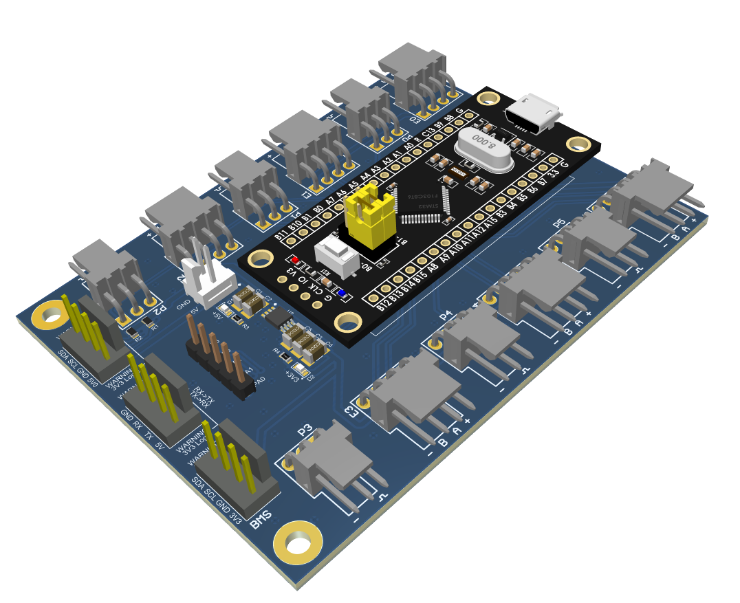
For the drive motor control boards, we are simply breaking out the IO to the motor drivers and the connector simply gets PWM. The accompanying connector next to each motor PWM signal is the quadrature encoder signals that provide positional feedback from the motors. The board also supports connection to the battery monitoring system, and also provides a header for IO that are currently unused.
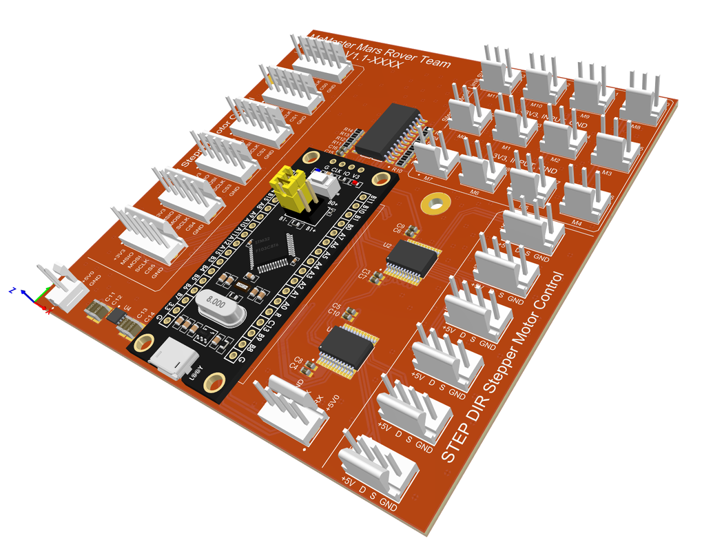
For the SMC, we realized that the initial design was a wiring nightmare, but the new revision does not look any better. Not all of the connectors on the board will be used, but we specifically provided as many as possible just in-case we decided to switch drivers at any point. After the first revision, we realized that the drivers we were using required 5V logic, so we also ensured that all the IO provided to the step and dir pins for the stepper motor drivers are 5V signals.
 We are excited to finalize the review process and finalize the new boards to eventually solidify our control boards.
There are plans in the work for new boards such as the OBC which will be implemented into our new architecture that will feature team-made BLDC drivers based on VESC and stepper drivers based on Mechaduino provided with full CAN support for easier wiring.
Discussions
Become a Hackaday.io Member
Create an account to leave a comment. Already have an account? Log In.