Components you need
- Screw Terminals × 2
- 1N4148 – General Purpose Fast Switching × 1
- P600G Diode × 1
- Capacitor 0.1uF × 2
- 5 mm LED: Red × 1
- 5 mm LED: Green × 1
- FQP27P06 60V P-Channel MOSFET × 1
- 2N3904 BJT × 3
- Resistor 10k ohm × 3
- Resistor 4.75k ohm × 2
- Through-Hole Resistor, 20 Kohm × 2
- Through-Hole Resistor, 18 Kohm × 1
- Resistor 10k ohm × 1
- Through-Hole Resistor, 3.9 Kohm × 1
- Resistor 1k ohm × 1
- 1N4735A Zener Single Diode × 1
- Rotary potentiometer (generic) × 1
Story
A simple solar charger must have 3 basic features built-in:
- It should be low cost.
- Layman friendly, and easy to build.
- Must be efficient enough to satisfy the fundamental battery charging needs.
The main property of this device to convert solar energy to electrical energy has made it very popular and now it's being strongly considered as the future solution for all electrical power crises or shortages.
Solar energy may be used directly for powering electrical equipment or simply stored in an appropriate storage device for later use.
Normally there's only one efficient way of storing electrical power, and it's by using rechargeable batteries.
Rechargeable batteries are probably the best and the most efficient way of collecting or storing electrical energy for later usage.
The energy from a solar cell or a solar panel can also be effectively stored so that it can be used as per one's own preference, normally after the sun has set or when it's dark and when the stored power becomes much needed for operating the lights.
Though it might look quite simple, charging a battery from a solar panel is never easy, because for two reasons:
The voltage from a solar panel can vary hugely, depending upon the incident sun rays, and the current also varies due to the same above reasons.
The above two reasons can make the charging parameters of a typical rechargeable battery very unpredictable and dangerous.
About this solar charger circuit
This solar charger is actually a Low Dropout Voltage (LDO) charger. It uses a series P-channel MOSFET linear regulator and a simple differential amplifier. Though it is mainly intended for charging 12V lead-acid batteries, the output charging voltage can be adjusted by the potentiometer.
Specifications
- Solar panel rating: 50W (4A, 12V nominal) (open circuit voltage: 18 to 20V)
- Output voltage range: 7 to 14V (adjustable) (not recommended for 6V applications)
- Max power dissipation: 16W (includes power dissipation of D3)
- Typical dropout voltage: 1.25V @ 4A
- Maximum current: 4A (current limiting provided by solar panel characteristics)
- Voltage regulation: 10mV (no load to full load)
- Battery discharge: 1mA (Chinese controls discharge at typically 5mA)
- LED indicators:
- RED: Solar panel active
- GREEN: Series regulator limiting current (fully charged or topping off)
- LED indicators:
RED: Solar panel active
GREEN: Series regulator limiting current (fully charged or topping off) - Reverse battery protection: Control shuts down if the battery is the inadvertently connected reverse.

LDO Solar Charge Control Circuit Operation
R4 and D1 form a 6V shunt Zener voltage reference. Q1 & Q2 make up the classic differential amplifier that amplifies the difference between the reference voltage and the feedback voltage from the arm of potentiometer R6. The output is taken from the collector of Q1 and drives the gate of P Channel MOSFET Q3. Differential voltage gain is probably in the order of 100 to 200. For best performance, I selected Q1 & Q2 for matched hFE. As the feedback voltage increases at the arm of R6, Q2 turns on harder and steals some of the emitter currents away from Q1. The collector current of Q1 follows the emitter current and drops less voltage across R1 thus reducing Vgs of Q3 and turning it off. C2 provides frequency compensation to prevent the amplifier from oscillating.
Q3 is dormant unless the battery is the connected reverse –should this happen, Q3 turns on and reduces the reference voltage input to zero thus turning Q1 & Q3 and preventing damaging battery current.
D3 prevents the battery voltage from appearing across an inactive solar panel.
Current Limiting
Current limiting is provided by the solar panel –it is not a commonly understood fact that the solar panel tends to be a constant current device. For this reason, a solar panel can withstand a short circuit. Therefore, the control does not need current limiting.
Voltage Adjustment
To set the voltage, disconnect the battery and connect a 1K dummy load resistor to the output. The resistor is necessary to shunt potential MOSFET leakage current, as well as the green, LED current.
Dropout Voltage
The input voltage exceeds the input voltage by 1.25V when charging at the maximum rate –the lower, the better. Low Dropout Voltage (LDO) is the catchphrase for anything under approximately 2V. This could potentially be reduced to below 1V by making D3 a Schottky rectifier.
Float Charge of Lead-Acid Batteries
This control charges the battery at a constant voltage and also maintains a charged battery (float charge). The float charge voltage specification is a little lower than the charge voltage, so to accommodate both voltages, a compromise is reached by simply reducing the voltage slightly –that is how ALL automotive systems operate. To obtain maximum charge in a 12V battery, set the control to 14 to 14.6V. Automotive systems further reduce voltage to 13 to 13.5V in order to accommodate high-temperature operation as the battery is usually located in the hot engine compartment – the battery has a negative thermal coefficient of voltage.
Thermal Management
This is a linear series regulator that dissipates significant power when the pass transistor is both conducting current and dropping voltage simultaneously –during maximum charge rate when the voltage drop is low, the heatsink runs warm –when the battery is fully charged and there is low charge current, the heatsink is cold –but when the battery starts to top off at maximum voltage, the heatsink runs very hot –such is the nature of a linear regulator. At 4A, Q3 drops 3.3V (assuming solar panel voltage is 18V)(the remaining 0.7V is the D3 voltage drop. P = 4A * 3.3V = 13.2W. The heatsink is rated at 3.9°C/W, so heatsink temperature rise = 13.2W * 3.9°C/W = 51.5°C. Adding the 25°C ambient temperature results in a heatsink temperature of 76.5°C. While this may seem very HOT to the touch, it is still cool to the transistor that is rated for a junction temperature of 175°C.
Putting all the stuff together
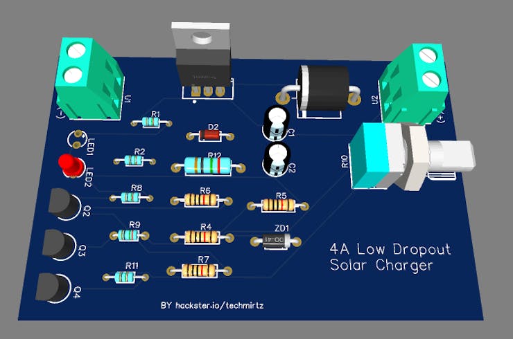
Follow the below steps to assemble the device at home easily:
- Download the Gerber files for the PCB from here or down below from files section.
- Go to PCBWay.com and upload the files get your PCBs at home at a very low price. Also, you can get a $5 Welcome Bonus. They are the most cost-effective and quality-oriented PCB manufacturers. You can order your prototype PCBs in a small quantity, as small as 5 pcs of PCB. In addition to the standard PCBs, we could also support advanced PCBs, FPC/rigid-flex PCBs, and other related services.
- Solder the components on the PCB as per the schematic and design shown below.
- Connect the input power supply (DC) in the input terminals from solar panels and using a multimeter, adjust the output voltage by adjusting the screw on the potentiometer.
- Connect the output terminals to the batteries to charge.
Note: Please be cautious while charging batteries as they can lead to serious accidents if not handled with care. The author or the sponsors should not be held responsible for any incident. This project is for educational purposes only.