 David H Haffner Sr
First part came in; The TCD1304AP CCD chip ! (received today Ebay $14.00)
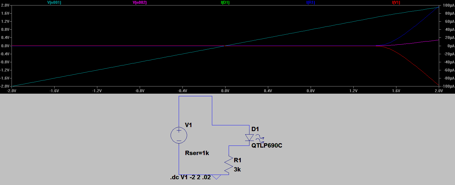
I had to modify Dave Allmon's schematic for the trigger switch, he had a 1k res in series with the frame pulse for the next CTS. The LED I am using is a 3mm 40mA indicator, and 1k wasn't cuttin' it, so according to LTspice, the 3k resistor brings me right to the 100mA range, so I should be fine, if I'm wrong please feel free to correct me!
Discussions
Become a Hackaday.io Member
Create an account to leave a comment. Already have an account? Log In.
Hey Ted, thanks for replying, yeah man, this SIM is great :) I wanted the current low so the LED lights up kind of dim. I know sounds weird but I've never made a circuit like this before and I'm not familar enough with signal voltage to current signal.
10mA should be fine your right, the pwr source on LTspice had a series resistor you could place (maybe I really didn't need that.
I am working from an updated schematic that I haven't posted yet, that has the trigger switch connected the way it should be (sorry 'bout that :)
Are you sure? yes | no
The source resistance in the voltage source just adds with the external one - It's a matter of style, but I usually never use the source resistance options and add explicit source resistors - you see 50 ohm resistors connected to a lot of my sources :-)
If you want a dim LED, 100uA might be enough (or even too much). Without knowing the exact specs, it's tough to tell. I usually have to test them out to find the right current/brightness trade-off when it matters, then choose a resistor afterwards.
Are you sure? yes | no
Hey Ted, I think that sounds like a good idea about just testing the LED brightness after, I'm finishing up on the new schematic, so it should make a lot more sense.
Are you sure? yes | no
Hi David,
It's good to see you using LTspice for simulations; it can save you a lot of bench time!
I'm not sure exactly where circuit you've simulated here fits into the previous schematic, but did you want 100 uA or 100mA? The simulation is showing 100uA, a very low current for normal LED indicators. Between 1 and 10 mA is probably around the right current for most 3mm indicator LEDs.
Are you sure? yes | no