 Ted Yapo
After some reading and thought over the holiday, I designed a PCB to hold 10x of the 4-chip 5W LEDs by Chanzon and others. This could alternately carry 1W or 3W LEDs.
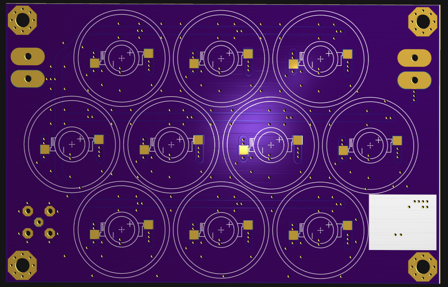
The front side of the board carries the LEDs and some inexpensive lens/reflectors:
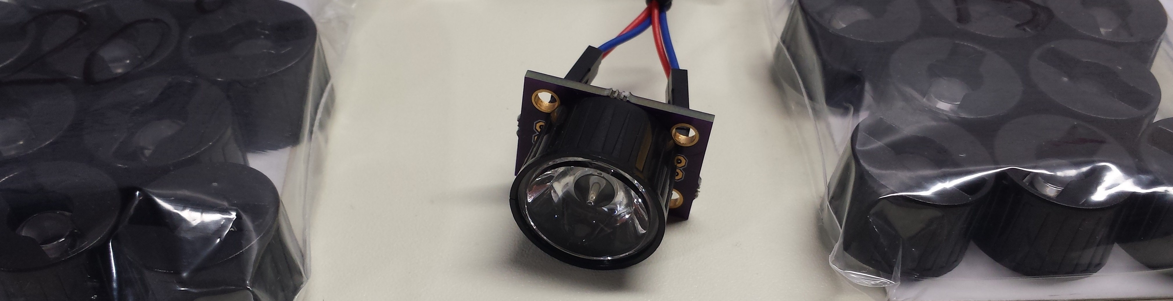
The lenses are available in a variety of beam angles; I have samples of a few different ones - not sure yet which will end up being most useful. What I do know is that the 120-degree angle of the bare LEDs makes it difficult to get light where you need it. Having lensed LEDs should make this much easier. The lenses press-fit on the LEDs - you can secure them with double-sided tape, but I think being able to change beam angles might come in handy.
The back of the board has a local flash circuit for each LED:
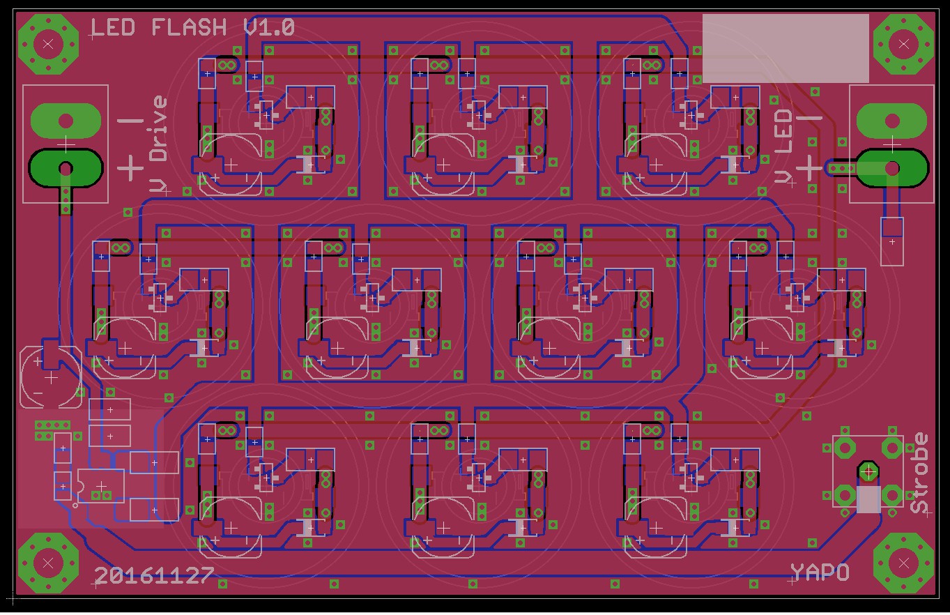
I went with aluminum polymer capacitors on this one - @K.C. Lee mentioned them as a possibility a while back, and on this board, I think they'll work out well. Specifically, with just two LED chips in series for each driver, I won't need more than about 20V of supply, maximum. I have some 25V caps selected - I tested a similar circuit with some 20V through-hole polymer caps I had on hand, and it seems to work very well. The low ESR of the cap allows lower voltage operation for the same current pulse, so higher-voltage caps aren't required. These capacitors are large enough (56 uF) that longer, lower-current pulses are also possible with this board - allowing more light for slower scenes. The capacitance doesn't drop with applied voltage like MLCCs :-)
This board is a step back from my original plan of a few LEDs driven with very high currents. Over the holiday, I had a chance to read Willert, et al. thoroughly. When I initially skimmed this paper, I was impressed that they were able to drive their LEDs with up to 250A. Upon further reading, I saw that the LED they were using, the CBT-120 from Luminus Devices, is rated for 18A continuous current! This large-area (12 mm^2) single-chip LED is designed for LED projectors, and costs over $100 in single quantities (it's actually not recommended for new designs; the replacements are a little more affordable, but not much). So, they're only over-driving the LEDs by a factor of 250/18 ~ 14x. If I want to stick to the same overdrive for 700mA max LEDs, I should pulse them with no more than around 10A. Of course, I will need more LEDs, which is how I got to this board design.
The other interesting point from the paper is that they claim fast rise-times are LED killers. In one passage, they claim that rise-times of 500ns or less at 250A can destroy their LEDs - although they don't describe the exact mechanism. In another place, they claim they drive LEDs with pulses as short as 100ns, though, so I'm not quite sure what to make of it. In any case, I have sites for MOSFET base resistors on the PCB to control the rise and fall times. While I'm waiting for these boards, I can do some experiments on the previous prototype to see if limiting the current pulse to around 14x overdrive and controlling the transition times extends the LED lifetime.
In that paper, they were driving 12 mm^2 LED chips (for a different application). On one board, I'll have 10 LEDs with 4 30x30mil chips each, for a total area of 23.2 mm^2. You could also populate the board with 3W LEDs (45x45 mil chips) for 13 mm^2 total - if pulsing the series/parallel 5W LEDs is a problem, I can always fall back to these.
One issue with the smaller current pulses is that I'll need more LEDs to get the required light output. I think that even 10 LEDs won't be enough, so I'm planning to be able to drive more of these boards as required - this will also make it easier to get light where it's needed, since each board can be independently positioned.
Pulse Hub
I thought about adding multiple outputs to the timer/controller board (still to be designed) to allow connection of multiple flash boards, but decided it would take up too much real estate on the board. Instead, I opted for an external "pulse hub" that can distribute the strobe signal from the controller board to multiple flash boards.
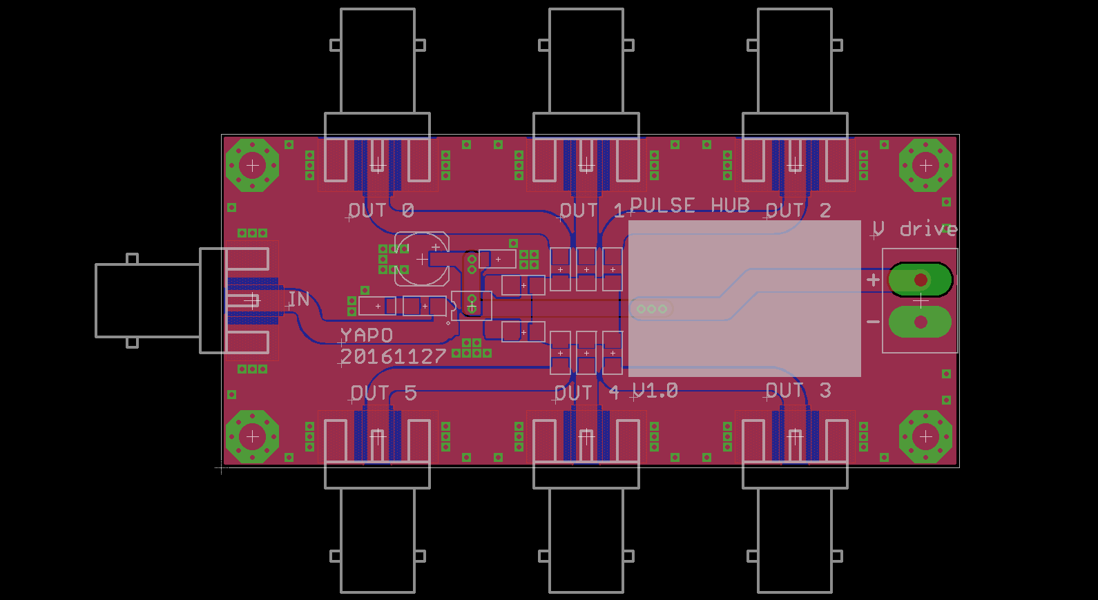
The eagle part I use shows BNC - I drew this one up a while ago, and it fits SMA or BNC connectors. I'll probably populate the board with SMA just because I have more SMA stuff around the lab. The board accepts the pulse output from the controller board, buffers it, and distributes it to up to six flash boards. With one hub, I could drive up to 60 5W LEDs, for a total LED chip area of 140 mm^2, and around 600A of current. It sounds like a lot, but I still expect to be light-starved. Using the right lenses and good flash placement, I still should be able to get decent images. Of course, I could chain these hubs to drive more boards, but that would get expensive very fast.
Now, I wait for the board and parts to arrive. I hate this part.
Discussions
Become a Hackaday.io Member
Create an account to leave a comment. Already have an account? Log In.