 Ted Yapo
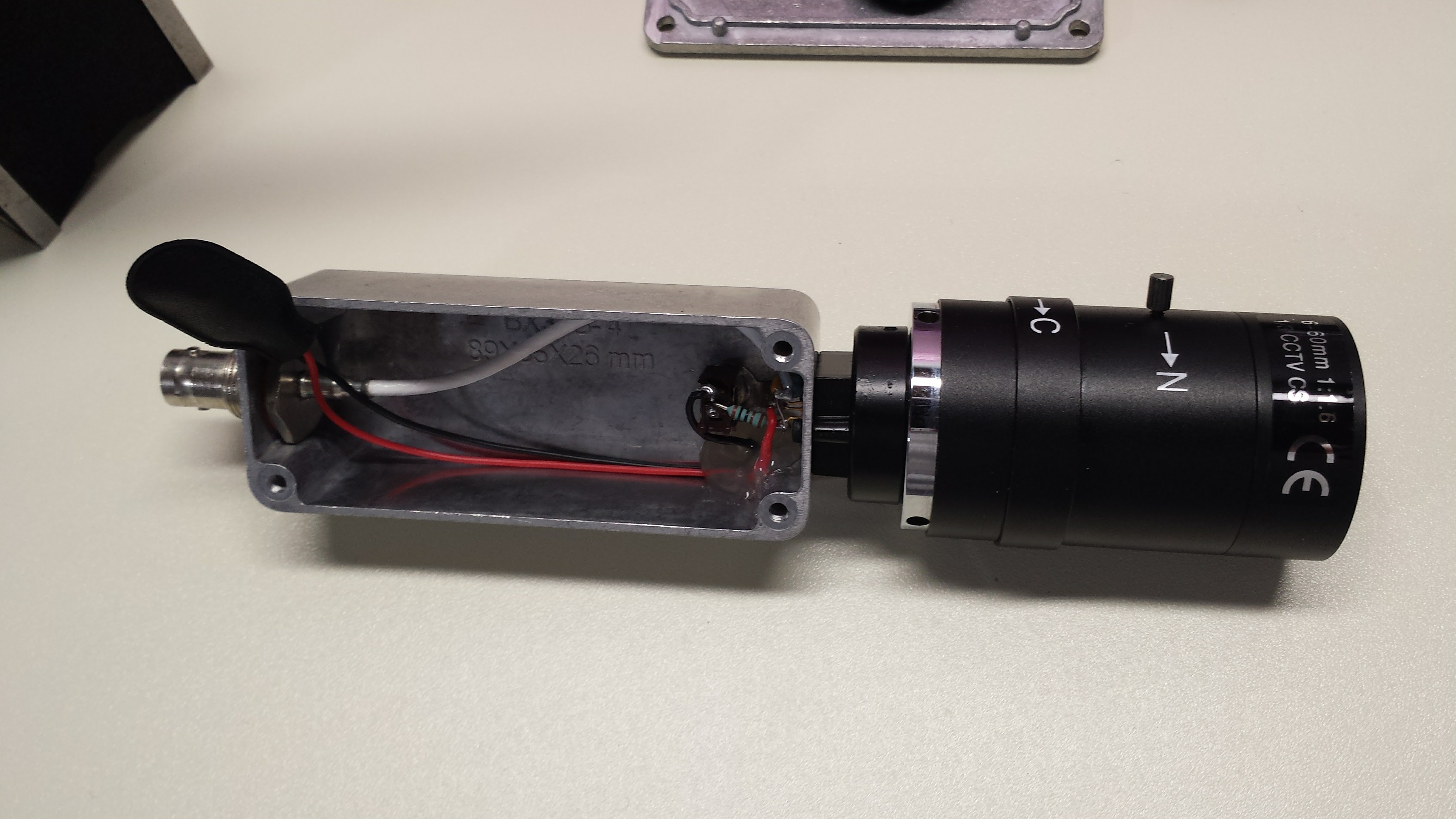
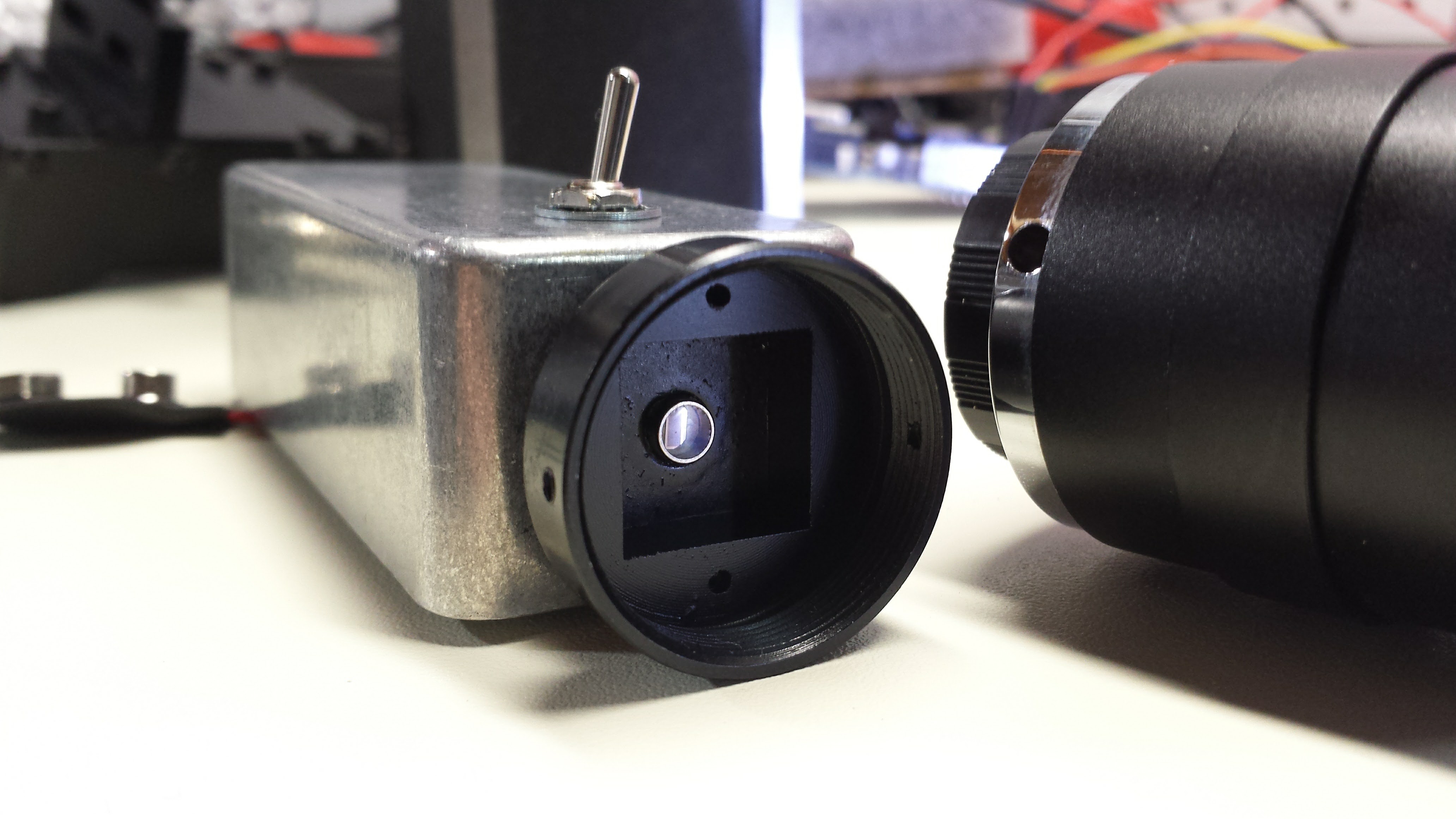
I tried two things yesterday: speeding the fall-time of the laser pulser and biasing the photodiode in the detector. Both improve performance. I ended up making this easy self-contained biased photodetector probe which shows a bandwidth of about 75 MHz. It features a C/CS - mount thread for attaching cheap surveillance camera lenses.
Here's the circuit, adapted from the photodiode tutorial on Thorlabs site:
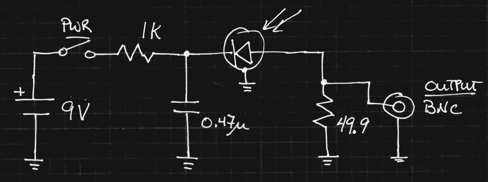
I omitted a regulator, obtaining the negative bias voltage directly from the battery. I would like to have had a higher voltage, but didn't want to use a larger case with multiple batteries. I also didn't want to use a switching supply - as it turns out, this well-shielded construction provides a very clean signal. No need to mess it up with switching hash. Next time I see one, I'll pick up a lithium 9V. It will last longer and provide a nearly constant 8.4V (unlike the alkaline 9V's which end up below 6). The diode sees a 25-ohm load (50 on each end of the cable), which cuts the signal in half, but raises the bandwidth and helps avoid reflections.
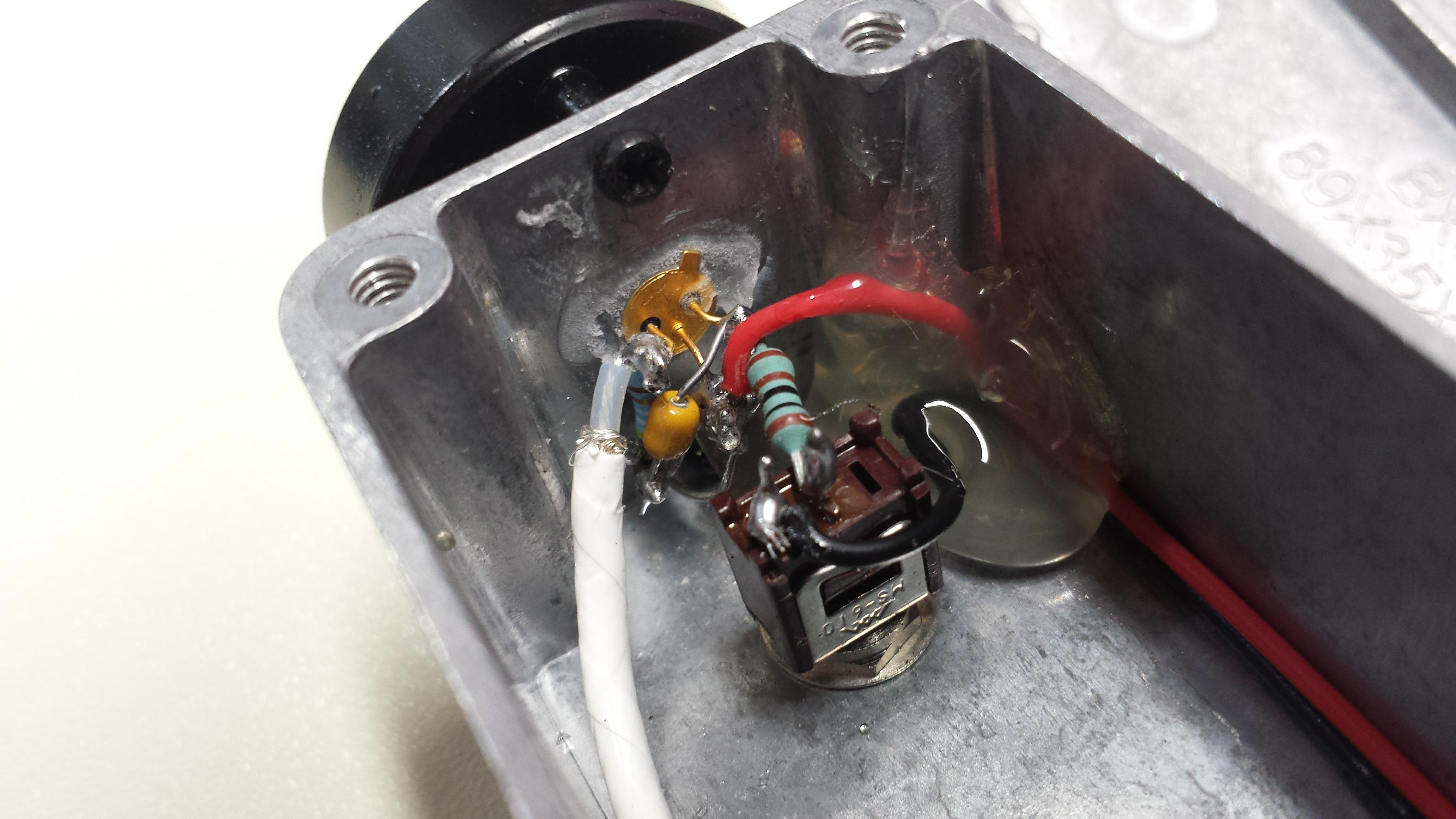
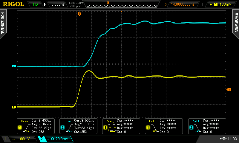
I used a surplus diode I had kicking around (Ebay, 2009). It's labeled "SD076-12-12" - probably an Advanced Photonix (now Luma) part, maybe similar to the SD076-11-31-211. That part claims rise times of 5 ns at 50V reverse bias, and with the version I have, I've seen better than that at even 9V reverse bias. I chose to use this part because it was the only (fast) one I had with an isolated cathode - it's in a three lead package (shown below) with separate connections for anode, cathode, and case. I guess cost drives manufacturers to use 2-leaded cases, but the three-lead one really helps with shielding this circuit, as shown in the schematic. Here's the rise time when the laser pulser is directed at the diode:

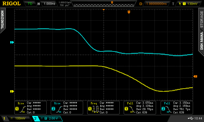
The auto-measurement on the scope pegs it at about 4.2 ns (cyan trace). There's almost no ringing: the tight construction and double-termination keep things clean. Here's the corresponding fall time:
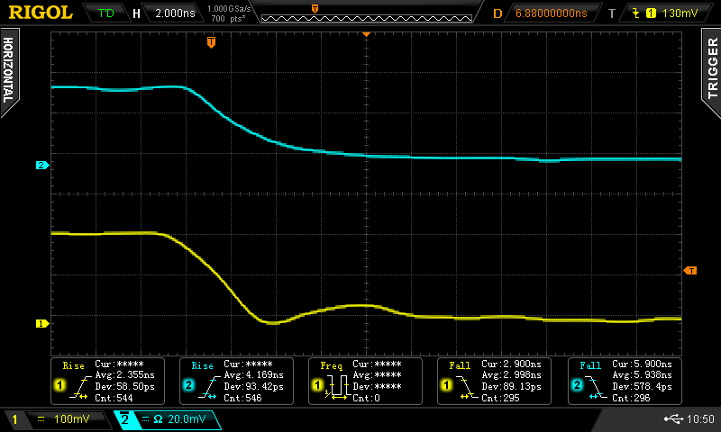
The fall time is a little longer, about 6 ns. Still not bad, and no ringing here, either. I think the nice waveforms are really helped by the construction:
Even though leaded parts are used, I tried to keep everything short and brought the 50-ohm cable right to the diode. The cs-mount is intended for board cameras, but it works just as well for attaching lenses to photodiodes. I found five of them for $7.47 on Amazon - I'm sure the same parts are on Ebay or AliExpress. They accept M2 screws.
The photodiode was inserted into a hole in the case, and held in place by soldering the case terminal to a solder lug inside. A drop of cyanoacrylate adhesive also helps keep it fixed. I painted the front of the case flat black to kill reflections. I didn't worry too much about the exact focal plane; you never want to focus light any smaller than the diode, anyway, because it causes funny non-linearities. Mostly the lens is useful for collecting more light and controlling the field of view. A CS-mount camera body cap conveniently screws on the front for protecting the diode.
What about the BPW34?
Since I can't even find documentation for the photodiode I used here, it's unlikely that anyone else will be able find one to use. So what about the lowly BPW34 that showed rise-times above 70ns unbiased? I threw together a quick breadboard to find out:
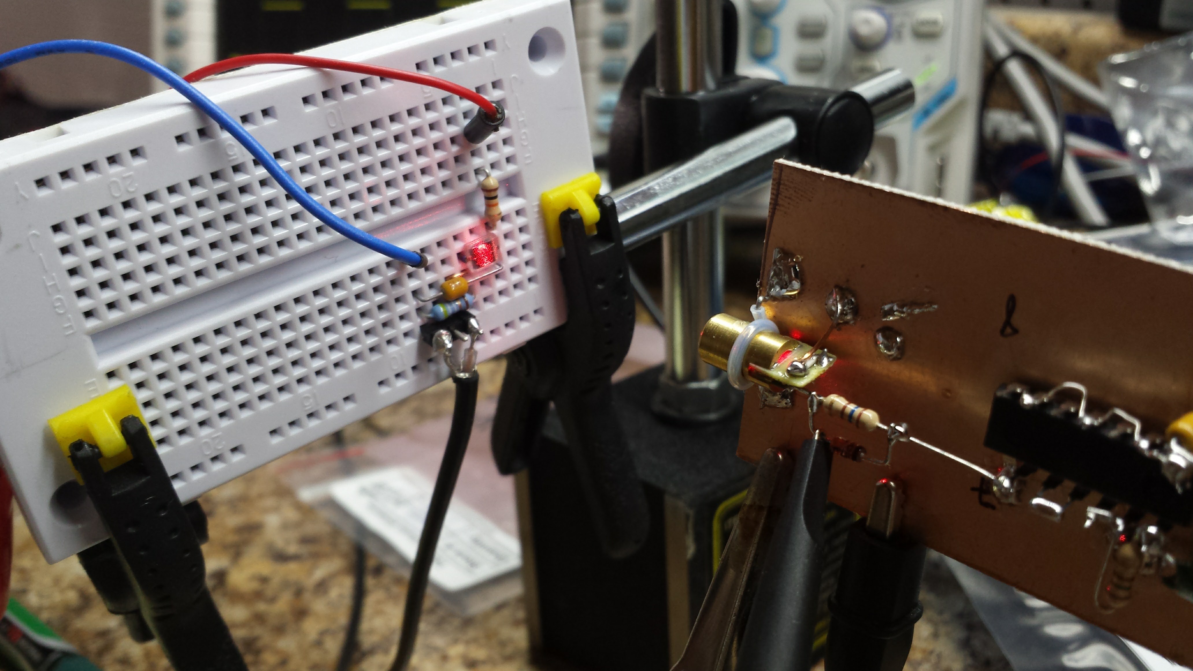
It's the same circuit shown above except using a variable supply for bias. At 5V reverse bias, you get this rise time:

All those wiggles are from the poor layout on the solderless breadboard. The scope measures about 17 ns rise time. Cranking the reverse bias to 20V speeds things up again:
Now, the rise time is under 10 ns. Using the 0.35/tr approximation, this detector has about a 36 MHz bandwidth. All these numbers are in line with Osram's datasheet, which specifies a 25 ns rise-time with 5V reverse bias into a 50-ohm load. The measured fall times are a little longer (22 ns @ -5V, 10 ns @ -20V). The only thing I don't like about the BPW34 is that it isn't shielded - shielded parts are much more expensive. I'm wondering if you could make a nice 3-terminal case out of a spent .22-caliber rifle cartridge - you don't need a front window since the BPW34 encapsulates the chip in epoxy. Or maybe just a section of brass tubing soldered to ground on a PCB.
Improving the Pulser
The slower fall time of the laser pulser was bothering me, so I tried a few things to speed it up. The first experiment was adding a small speedup capacitor across the 160-ohm resistor. This sped up the edge, but also made things ring badly - I suspect my poor layout - look at that long resistor lead in the image above. Speedup caps and stray inductances make for some ringy pulses.
The next experiment was adding a reverse diode across the resistor to help pull charge out of the laser diode junction during turn-off. I was looking for 1N5711's, but I found a bag of FDH700's first. I don't know if they make this diode anymore, but it's like a 1N4148 on steroids - 1.5 pF of junction capacitance and a 900 ps switching time (the 1N4148 is 4ns - too slow to help here). If you find your bag of 1N5711's first, they might be even better. In any case, here's the fall time with the diode in place (measured with the APD module):
The fall time is now around 2.2ns, where it had been around 2.9 before. Not perfect, but I'll take it.
Mysterious Photodiode Behavior
In testing these photodiode circuits, I observed some very odd behavior I haven't seen addressed anywhere. Maybe a reader will recognize what I'm seeing. I've seen this to some extent with each of the diodes I tried in this circuit. Here's the deal - the waveform output from the detector depends on how much of the photodiode is illuminated. I've read that you want to keep the diode evenly illuminated to maintain a linear response - over-illuminated regions can develop a local forward bias that distorts the signal. Here's what happens with a fully illuminated diode (left), partially illuminated diode (middle), and slightly illuminated diode (right). The vertical scale has been changed to keep the waveforms visible - the partially illuminated versions have an understandably lower amplitude.
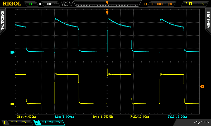
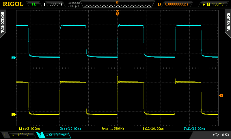
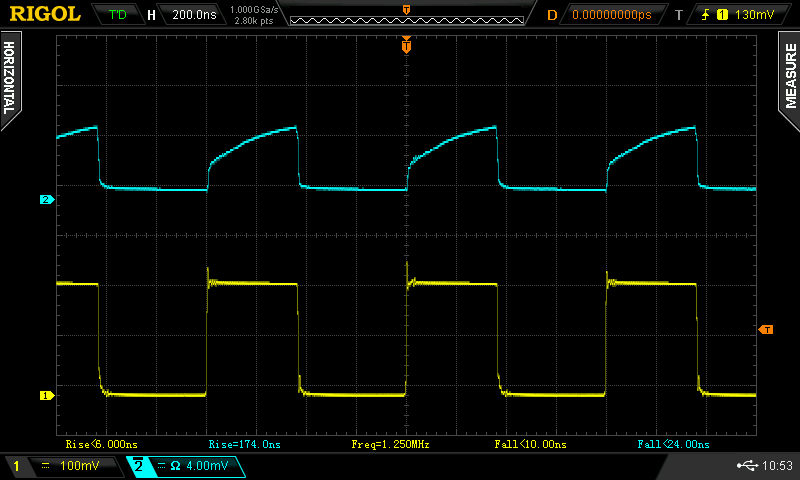
I can't even explain the sloped response for the fully illuminated diode. At first, I thought maybe the bypass cap was too small and the bias supply was sagging, but probing that point showed no significant droop. I also tried adding some neutral density filters in the beam, thinking it might be the total brightness instead of the illuminated diode area, but the results were the same. The overall behavior reminds me a little of scope calibration - you can tune the waveform by moving the detector slightly off axis to get a nice square wave (which is what I did for the second image). Any clues?
EDIT 20161113
Another clue. The effect only seems to happen in one direction on the diode. The chip is rectangular:

With the laser moved on the long axis, the waveform doesn't change shape dramatically, except in amplitude. Smaller amplitudes do seem to have a little less "cusp" to them.
However, when the beam is moved in the short axis, the waveform changes shape dramatically. This must have something to do with the terminals being on that axis.
I hadn't noticed the directionality before, and when I went to test it again, I couldn't change the waveform shape like before - then I rotated the detector, and it "worked" again.
To David's point (below) about saturation, the peak voltage measured during the pulse is around 28 mV. Across a 25-ohm load, that's 1.1 mA of current. Is that saturated? It sounds large for a 2.9 mm^2 diode.
Bizarrely, similar diodes seem to cost around $50 each on Digikey. I ebayed these for $1.50 each. Huzzah for ebay! Also note that the $1 BPW34 is almost as good.
Discussions
Become a Hackaday.io Member
Create an account to leave a comment. Already have an account? Log In.
I'm a little late to the party, but here's the quick fix to your higher bias voltage:
https://www.amazon.com/Exell-Battery-415A-Alkaline-BLR102/dp/B00CQ8CBJW
May be a little long to fit in the box though.
Are you sure? yes | no
you have to wonder what's inside that thing! I'd love to see someone slice one open and see thirty aaa batteries flop out onto the deck.
Are you sure? yes | no
Oh, you are too kind, I'm just good at finding what I want! Yeah, I can agree that the clipping effect can be attributed to just the highest peak intensity, but the ND filters will only attenuate the luminance. I studied the circuit design, and the CAP at 0.47 micro farads, maybe raise it to a 0.1 or .25 for a faster fall and rise time?
oh, before I forget, here is where I find a lot of obscure parts data;
http://www.datasheetarchive.com/shortform-datasheet/SD076-12-12-211.html
Are you sure? yes | no
I can try a smaller cap to see if it changes the response - or add a 0.01u across the existing one (hoping for no resonances). I bought a reel of these 0.47's on ebay a few years ago, and they've proven pretty good at high frequencies, but 100 MHz might be pushing it. Good point.
Are you sure? yes | no
I sent you 2 plots on your private email, I found your wave forms and it looks like it is caused by decreased load resistance.
Are you sure? yes | no
Ok, you have my attention on this one, the first illuminated wave form on the fully illuminated scan is akin to "clipping," over saturation of the "active" area on the photo diode's surface. What is the NEP? (noise-equivalent power) an output bandwidth of one hertz is equivalent to half a second of integration time, a smaller NEP corresponds to a more sensitive detector.
Here is the diode you are using;
SD076-12-12-211 Silicon Detector Corporation
Search: SD076-12-12-211
Blue-Optimized Photodiode
Photosensitive Area (mm2)=2.9
Semiconductor Material=Silicon
Spectral Response Low (m)=290n
Spectral Response High (m)=1.1u
Re Min.(A/W) Responsivity=.50
t(resp) Max.(s) Response Time=46n
NEP Max.(W/(Hz)1/2)=.12f
Ioff Max.(A) Off-state Current=450p
@V(R) (V) (Test Condition)=5.0
C(T) Max. (F) Capacitance=290p
Package=TO-46
Are you sure? yes | no
You, sir, are a wizard. Where did you find the specs on that diode?? Thanks!
I'm going to take a little time to re-measure the waveforms with and without ND filters to make sure this isn't just a saturation effect. The thing that makes me think something else is at work is the funny waveforms for small illumination area. I would think that if it were just saturation, small to medium illumination areas would look the same, and you'd only see changes at the high end.
Are you sure? yes | no