 Ted Yapo
I made this one before I had any of the MOSFET gate driver ICs. Of course, you could argue that the BJTs I've used here could make nice gate drivers themselves (the ZTX718 lists that as a primary application on the datasheet). But, I decided to see what I could do with BJTs alone.
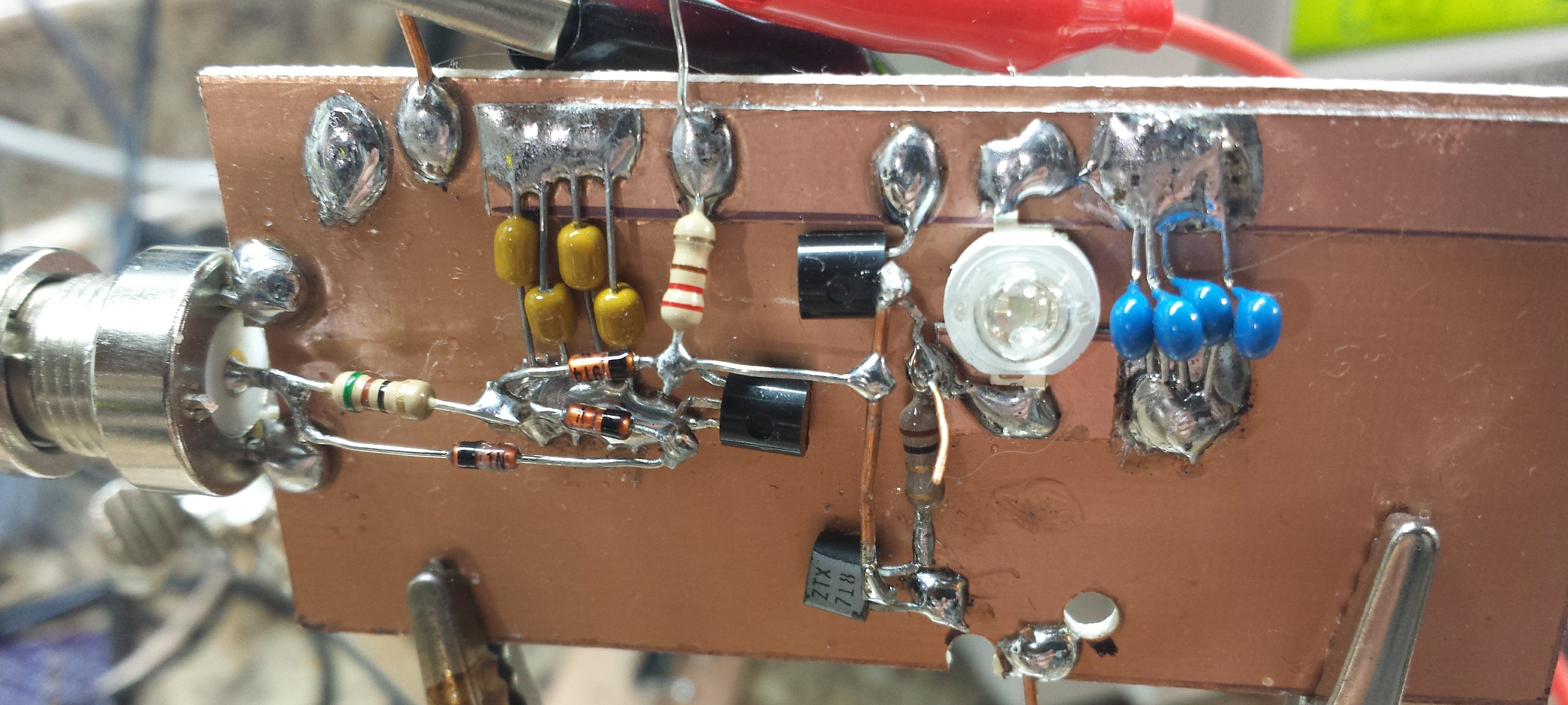
I made this from jellybeans, because everyone has jars of them lying around. The ZTX718 doesn't qualify, but I originally had a 2N4403 in there instead :-)
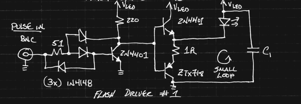
I worked hard to overcome the storage time in the first common-emitter stage, hauling out the big guns: a three-diode Baker clamp. In simulation it appears to work pretty well. Here are the current pulses through the LED (yellow) for supply voltages from 6 to 24V compared with the input pulse (magenta):
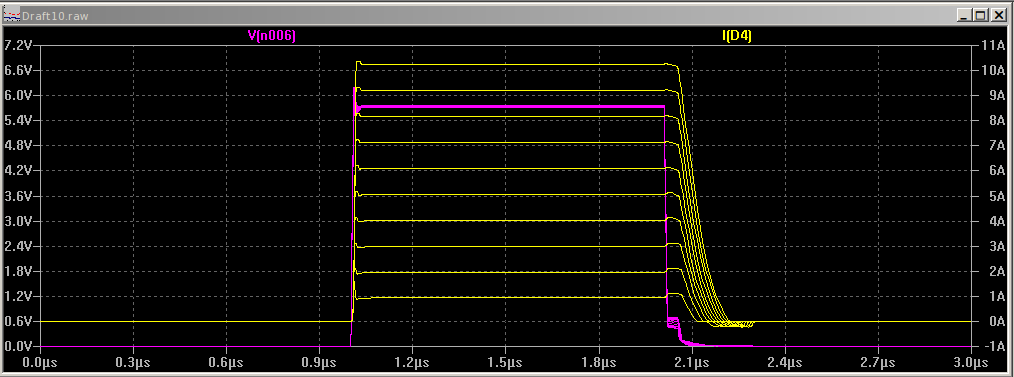
On the bench, though, as I turned up the voltage, the storage/fall time got longer and longer - much worse than this simulation. I accidentally deleted the oscilloscope screenshots, so I'll have to update this log later. I have two suspicions. First, the supply voltage may have been sagging due to the heavy current pulses, so there wasn't enough drive through the 220-ohm resistor during the falling edge. Another possibility is bad layout (I know you're eyeing those big current loops). I'm still interested in figuring this out, but I've basically abandoned this circuit for the flash. I had originally thought it would be useful to have a number of these circuits driving individual LEDs in a big array. I might end up back there, but for now, I think a smaller number of drivers each with a handful of LED chips is the way to go, and MOSFETs with commercial driver ICs eliminate the storage time issues entirely.
Baker Clamps
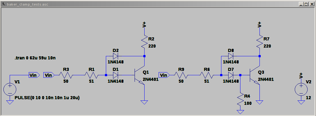
I did take the opportunity to explore various baker clamp topologies in simulation, though. Here are some interesting results. Three circuits I compared:
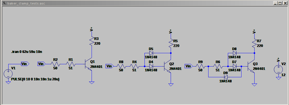
From left to right, no clamp, a 2-diode clamp, and a 3-diode clamp. They're all driven from a 50-ohm source resistance. Here are the waveforms:
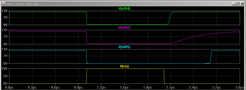
On the bottom is the driving waveform (before the source resistance). The top trace shows the output of the three-diode clamp, which doesn't show appreciable storage time. In the middle is the 2-diode clamp. I didn't expect the exponential tail here. Finally, with no clamp, you see about 500 ns of delay between end of the input and output pulses.
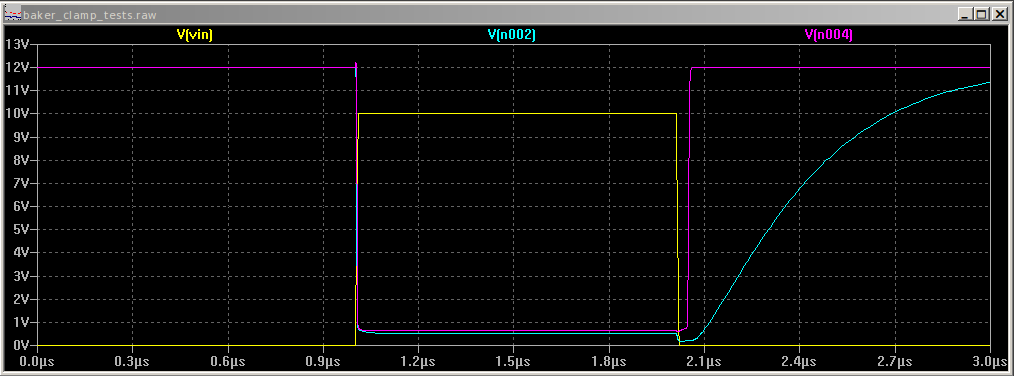
The tail on the 2-diode clamp bothered me - the problem is that the input can't pull the base down through the diode. This gets fixed in the 3-diode version with another (reverse) diode, but you can also add a resistor to pull down the base (right hand side):
This resistor does a good job of eliminating the tail (magenta trace has R4, cyan trace does not):
I find it very interesting that this base resistor is omitted from most discussions of the 2-diode Baker clamp. Maybe because the original circuit was made with germanium PNPs (and possibly Ge diodes) in the 1950s, and they didn't require this resistor?
Schottky Clamps
Of course, you can do even better with a Schottky clamp:

The Schottky cuts off another 50ns or so (cyan trace) of the 3-diode version (magenta):

I knew this when I built the circuit above, but I used the 1N4148s because I couldn't find any of my through-hole Schottky's when I went to assemble it, and I didn't feel like dealing with SOT-23's (I easily found the reel of BAT54s).
Discussions
Become a Hackaday.io Member
Create an account to leave a comment. Already have an account? Log In.
Hah! There's some great info up in here...
Are you sure? yes | no
No wonder HaD is now my favorite website :-P
Are you sure? yes | no
Hi Ted,
I did not have much success with Baker Clamps.
Have a look Johnny's site: http://lovqvist.net/DTL/NOT.html, he has played with Baker Clamps and got good results.
Johnny's design works well because the source discharges the base capacitance via the schottky diode and the diode clamp limits collector-emitter saturation.
You may want to consider noise immunity in your design as well (which is why I don't use his design for CPU design).
Transistors are limited by slew rate, so for speed, lower voltages work better, if speed is the key criteria.
With a 2N3904, I can get down to 30 ns propagation delay with the conventional DTL schematic. Johnny's design is faster but the noise immunity is about 0.3v (versus 1.2v).
So his design may work for you?
Regards AlanX
Are you sure? yes | no
@matseng and @Andrew Starr might have interesting experience to share, since they designes #AYTABTU - Discrete Computer and #The T-1: A discrete 8-bit Stack Computer :-)
Are you sure? yes | no
yes, all of a sudden it makes sense why TTL outputs are so good at sinking current and lousy at sourcing it - they need good low side drive to turn off the next stage. The L->H transitions are easy.
Are you sure? yes | no
Wohah... Another amazing log :-) That's an excellent thing to know for all the #Hackaday TTLers !
"Forget your 1N4148, get Schottky !"
Are you sure? yes | no
I concur
Are you sure? yes | no
How many BAT54's you have in that computer of yours? Has to be thousands...
Are you sure? yes | no
1 per transistor more or less, so yeah...a lot :)
Are you sure? yes | no