 mras2an
All schemas and PCB (gerber), can be downloaded on the VinyGo git project. https://github.com/Mras2an/VinyGo/tree/master/02_Hardware
4.1) Structural diagram
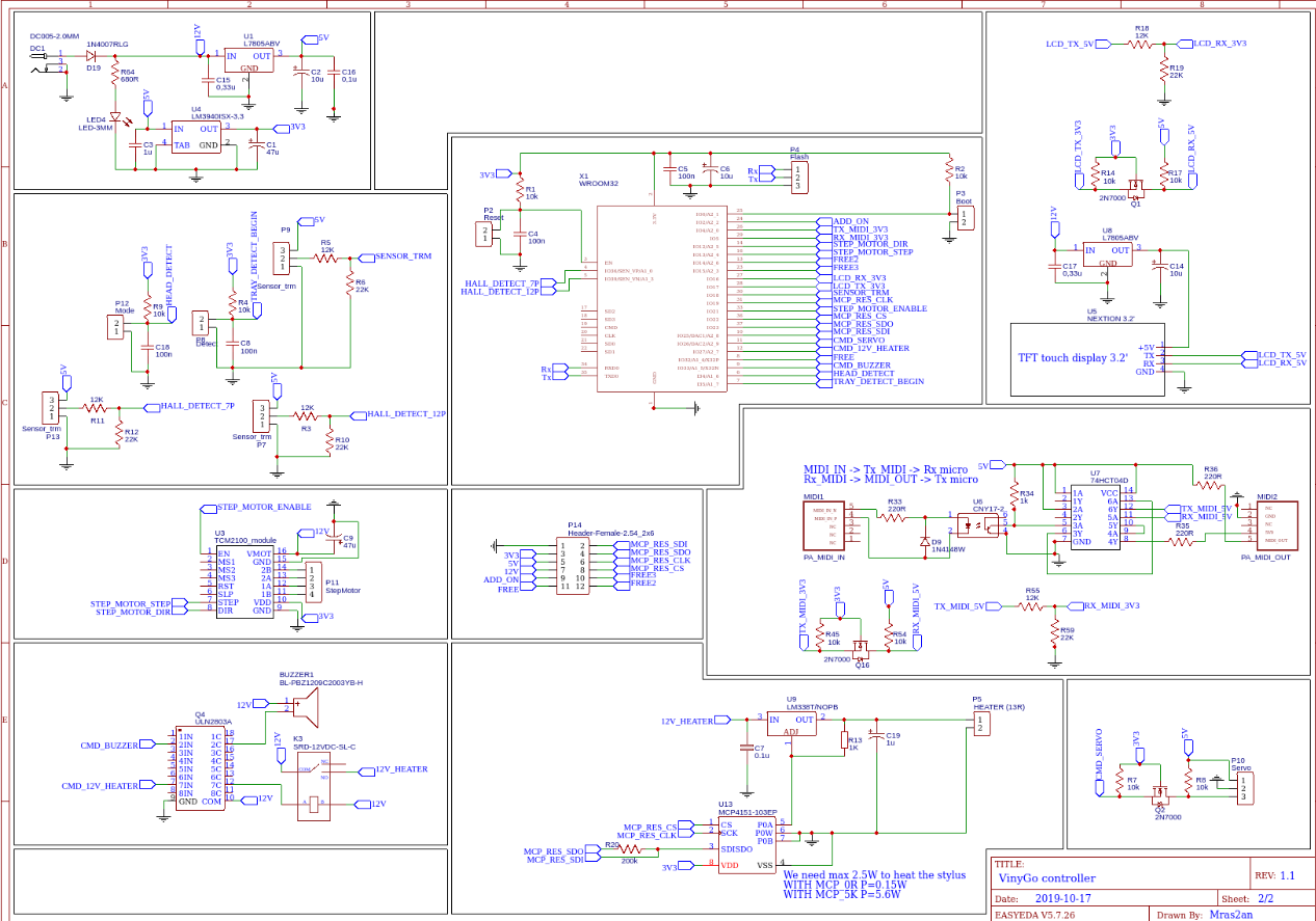
4.1.1) FS1.1: Power supply
Create power for all features on VinyGo Board. Input voltage 12V 5A, output voltage, +12v, +5V, +3.3V, 0V.

DC1: 12V connector
D19: Protection diode.
R64, LED4: Bleu LED,information on the powered board.
C1, C2: Polarized chemical capacitors. They perform the filtering, and allow a decoupling in case of power supply
C2, C16, C3: Plastic capacitor, serves as an anti-parasite to suppress high frequencies (it is recommended in the technical documentation).
U1: 5V regulator, it allows to regulate the input voltage 12V DC in a voltage of 5V DC. According to the manufacturer's documentation of the 78XX, a minimum input voltage of the output voltage plus Vdrop (2V) or Ve = Vs + Vdrop = 5 + 2 = 7V minimum is required for proper operation.
U4: 3.3V LDO, it allows to regulate the input voltage 5V DC in a voltage of 3.3V DC.
4.1.1.1) Calculation of a radiator
Pmax = (Tj – Ta)/RTHja = (125-25)/65 = 1,5W
Supposition for 3V3 WROOM32: 90mA, other 50mA max
Isystem = 90+50 = 140mA
Putil(3.3V) = Isystéme*(Ve-Vs) = 140*10^-3*(12-3.3) = 1,218W
Putil<Pmax.
Supposition for 5V: Servo motor 120mA, Sensors 40mA, MIDI 10mA, other 60mA
Isystem = 120+40+10+60 = 230mA
Putil(5V) = Isystéme*(Ve-Vs) = 230*10^-3*(12-5) = 1,61W
Putil>Pmax.
The utility of a radiator for regulators 3V3 is not essential at room temperature.
But we need a radiator for 5v.
4.1.2) FS1.2: LCD touch screen
Display digital information for the user and make order acquisition by the microcontroller.

Q1, R14, R14: Convertor 3.3V to 5V
R18, R19: Convertor 5V to 3.3V
U5: Nextion HMI display connects to peripheral MCU via TTL Serial (5V, TX, RX, GND) to provide event notifications that peripheral MCU can act on, the peripheral MCU can easily update progress, and status back to Nextion display utilizing simple ASCII text-based instructions.
U8: 5V regulator, it allows to regulate the input voltage 12V DC in a voltage of 5V DC. According to the manufacturer's documentation of the 78XX, a minimum input voltage of the output voltage plus Vdrop (2V) or Ve = Vs + Vdrop = 5 + 2 = 7V minimum is required for proper operation.
4.1.2.1) Calculation of a radiator
Pmax = (Tj – Ta)/RTHja = (125-25)/65 = 1,5W
Supposition for LCD 5v: 130mA max
Isystem = 130mA
Putil(5V) = Isystéme*(Ve-Vs) = 130*10^-3*(12-5) = 0,91W
Putil<Pmax.
The utility of a radiator for LCD is not essential at room temperature.
4.1.3) FS1.3: Sensors
Detection of engraving head positions.

P13, R11, R12: Connector for hall sensor to detect end of 7p vinyl.
P7, R3, R10: Connector for hall sensor to detect end of 12p vinyl.
P12, R9, C18: Connector to detect if the engraving head is up or down
P8, R4, C8: Connector to detect if the tray is on begin position.
P9, R5, R6: NOT use
4.1.4) FS1.4: MIDI
Technical standard that describes a communications protocol, digital interface, and electrical connectors that connect a wide variety of electronic musical instruments, computers, and related audio devices for playing.

Q16, R45, R54: Convertor 3.3V to 5V
R55, R59: Convertor 5V to 3.3V
MIDI1, MIDI2, Connector In and Out for MIDI.
R33, D9, U6, U7: Convertor of MIDI to Rx UART.
R35, UT: Convertor of Tx UART to MIDI.
4.1.5) FS1.5: Uc
Ensures through a programmed treatment (software) the acquisition, processing and return of information. It communicates with the motors(PWM), sensors(GPIO), LCD(UART), MIDI commands(UART), and offers inputs / outputs to add additional functionality like VinyGo sound mastering.

R1, C4, P2: Allows a reset on the wroom32.
C5, C6: Used to filter high and low frequencies.
P4: Allows programming the wroom32 via a UART.
P3: Set wroom32 to programming mode.
4.1.5.1) Definition of the inputs, outputs of the micro-controller.
4.1.5.1.1) Inputs
Boot: Set the WROOM32 to programming mode.
Reset: Allows a reset on the WROOM32.
Flash: Send binary to the wroom32 memory.
HALL_DETECT_7P: Detects end of 7p vinyl.
HALL_DETECT_12P: Detects end of 12p vinyl.
RX_MIDI_3V3: UART signal for MIDI protocol.
LCD_RX_3V3: UART signal for LCD protocol.
SENSOR_TRM: NOT use.
MCP_RES_SDO: SPI data from Digital POT.
HEAD_DETECT: Detect if the engraving head is UP or DOWN.
TRAY_DETECT_BEGIN: Detects if the tray is at the initial position.
4.1.5.1.2) Output
TX_MIDI_3V3: UART signal for MIDI protocol.
STEP_MOTOR_DIR: Select the motor direction.
STEP_MOTOR_STEP: PWM signal.
LCD_TX_3V3: UART signal for LCD protocol.
MCP_RES_CLK: SPI clock for Digital POT.
STEP_MOTOR_ENABLE: Enable step motor driver
MCP_RES_CS: SPI select for Digital POT.
MCP_RES_SDI: SPI data for Digital POT.
CMD_SERVO: PWM signal
CMD_12V_HEATER: Enable heating
CDM_BUZZER: Buzzer signal.
4.1.6) FS1.6: Heating stylus
Heat the diamond for a better cutting. Max 500mA for 5v, see diamond specification for more details.

U13, R20: SPI Digital POT
U9, R13, U13: Adjustable linear voltage regulators, capable of delivering more than 5 A at an output voltage between 1.25 and 32 V.
C7: Polarized chemical capacitors. They perform the filtering, and allow a decoupling in case of power supply
C19: Plastic capacitor, serves as an anti-parasite to suppress high frequencies (it is recommended in the technical documentation).
4.1.6.1) Calculation of a radiator
Pmax = (Tj – Ta)/RTHja = (125-25)/65 = 1,5W
Supposition for 5V heating: 500mA
Isystem = 500mA
Putil(5V) = Isystéme*(Ve-Vs) = 500*10^-3*(12-5) = 3,5W
Putil>Pmax.
We need a radiator for heating regulators.
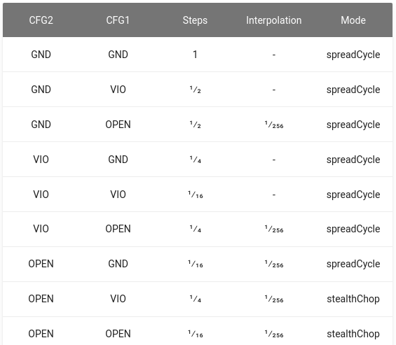
4.1.7) FS1.7: Step motor
Move the engraving head on the X axis.

U3: Provides an integrated motor driver solution for 3D-Printing, Cameras, Scanners and other automated equipment applications. The device has an integrated micro-stepping indexer.
P11: Step motor connector.
C9: Polarized chemical capacitors. They perform the filtering, and allow a decoupling in case of power supply (it is recommended in the technical documentation).
4.1.8) FS1.8 Servo motor
Move the engraving head on the Z axis.

Q2, R7, R8 Convertor 3.3V to 5V for servo motor PWM signal.
Discussions
Become a Hackaday.io Member
Create an account to leave a comment. Already have an account? Log In.