 DIY GUY Chris
If you don't like reading then maybe a video is a good option for you, just display the above video and watch :)
I Hope you already enjoyed my previous post about "How to Make a PCB Business Card" and you are ready for a new one, as usual I try to pickup some useful and interesting content to bring it to the table so you as a follower get some new knowledge and skills, today's topic is how create your own practicing circuit board to interface with the Arduino Portenta dev board which is an "industrial board" as it is described on the manufacturer website.
During the making of this project, we tried to make sure that this post will be the best guide for to combine some practicing tasks on hardware designing and assembly, plus the software tests that we have made as well. You will get through some softwares like the Arduino IDE and Altium designer.
This project is so handy to make just when you select the appropriate documents and support, talking about the support, I was in a tough mission to pickup the appropriate manufacter to prduce my practicing platform and it was landed on JLCPCB, these guys just support this project by providing the Printed Circuit Board that we needed for this project.
What you will learn from this project :
- Learn the necessary details about Arduino Portenta.
- Prepare the schematic of the practicing board on Altium Desiger.
- Create the appropriate PCB design.
- Solder the electronic parts to the PCB.
- Start the first test and validate the project.
About the Arduino Portenta Board
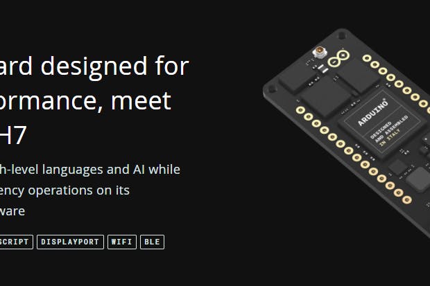
Maybe this is something new to you because it has been released lately and wasn't highly integrated in the prototyping category! the Arduino Portenta board has been classified as a "Pro" industrial board for advanced projects where high performance is needed.
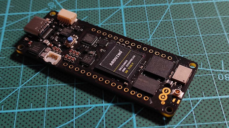
Even a new Arduino web-section has been built for this topic, well, I'm talking about the new Arduino Pro website. There you can find the list of the industrial Arduino boards, Portenta is on the head of the list for sure. Even the theme is not like the classic Arduino stuff and it has more dark colors and you can notice this from the Portenta board itself which is built from a black soldermask Circuit board. Actually the Arduino community are keeping this color for all their "Pro" products.
The boards list of the "Pro" category is not a long one since it has only Arduino Portenta, the Nano Family and Arduino MKR, now these Nano and MKR are names that might be look familiar for you.
What makes the Portenta classified as "Pro" board!
The classic Arduino boards that we used to play with have some limited peripherals which requires the add of some external gadgets and shields to expand the board features, its MCUs registers are based on 8-bits architecture which is a limit in front on the execution of some specific tasks where high decoding is needed, high decoding and high execution speed as well. all these details are not limited in the Arduino Portenta board that comes with a beastly dual core processor from STmicroelectronics, oh yeah! We are talking about 32-bits MCU architecture here, high speed and basically high everything! having fun with such dev board is not only concerned with the MCU Architechture only but also with the many added peripherials arround it, the borad comes with a built-in WIFI and Bluetooth by Murata Electronics and many more ICs that you can find their full details here
You can notice that there is a full Family Gadgets for the Portenta, this family includes some Shields and board industrial carrier for the H7 Portenta. I know what you are willing to say! a question about this "H7" label maybe! actually it comes from the dual core processor since the board is built around two processors H7 and H4, these two processors are sharing the access to all the board peripherals, in another word you can say that you are having two brains in one body, or two Arduinos in one board. Yes yes I know what you are asking now! the answer is "yeah" you can run two different programs in this Portenta :D (two void loop functions running at the same time). Now it is my turn to ask a question, why they call it "Portenta H7" and not just "Portenta" hummm maybe because there will be more other Portenta versions with different processors. Let's wait and see.
How Could We Tame This Portenta Beast
Now we get to the heart of this post, remember that I'm writing this article to explain how to get access to the Portenta peripherals.


It says that the board has the same Arduino MKR Family header connectors, it means that if we solder some SIL connectors over the board sides then we can access to the processor's ports, unfortunately I’m not that kind of a person who will screw up the awesome looking of a 85 bucks board with some ugly connectors, even the board comes with no connectors, so I decided to use the board through its High density connectors.

Yes! Those tiny connectors at the bottom of the board, how to access them!? that’s the question.

Actually these mezzanine connectors have 80 pins each and provide the access to all the board peripherals, so I decided to create my own circuit board to breakout these mezzanine connectors and just plug in the Portenta board and use it, a kind of plug-play or a Host-Guest technique. This will keep the Portenta brand-new for ever and also will help to explore more boards peripherals, also it would save money because we will be plugging the Portenta in a super cheap circuit board.
Let's Start Designing Our Customized Board
If you are new to my "articles style" then let me tell you that it is always this way, I prepare a designing section where I put in details the schematic blocs and then we move to produce the designed board so you can consider that this step is one of the most important ones in this post.
As I mentioned in the previous section I will use the Portenta board through its high density connectors so defining the appropriate part reference that will receive the Portenta is probably the most important here, because the mezzanine connectors are two many and almost identical so we need to pickup the appropriate one carefully.

Actually Arduino community makes it easy through their Store web-page where they are posting "Interactive Board Viewer" that shows Portenta product in SCH mode,PCB mode and 3D mode. This feature is powered by Altium 365, all board components are clickable and you can just show-up the component's proprieties and there you get the part number as reference to use it while you search for your needed components.
The Mezzanine connectors used in the Portenta H7 board are Surface mount 80 pins HDR connectors by HIROSE manufacturer (this is why we call it HRS conn) and their part number is DF40C-80DP-0.4V(51), looking through the manufacturer datasheet it says that the appropriate male connectors for such reference is the DF40C-80DS-0.4V(51) and this is exactly what we used in our schematic design.
Oh hey! about the design, remember that this section is for the schematic so let's just run our circuit designing tool and start drawing, this time I will get started with Altium designer to draw schem and PCB for this project.
I tell you what! You've been a good reader of this article and you deserve a gift! yes a special gift for you: you can have a free Altium design trial through this link, but hey, keep this secret and I will bring you more gifts ;)

I attached the schem that I made for my host board and let me just say that it wasn't difficult to use the designing tool especially with the help of Octopart, it is a kind of schem and footprint online warehouse, there you can find basically all the packages and footprints of the parts that you need.

I added some LEDs to my design to perform some programming tests on the digital and PWM pins, some slide switches for digital inputs, it’s good to have also a motor driver for some power control, and I added a MAX6675 to test the ability of executing some libraries on my code.
Basically all the parts footprints are available in Altium designer so I just moved through the schem process smoothly.
Straight to the PCB
You still reading hummm then I can guess that my post is interesting enough to catch your mind! :D
We are at the fun part, the PCB designing makes me feel always that I'm in the "pro" stage because it feels like we are making something advanced here, yeah I mean the circuit board design, it will be similar to those fancy boards that we are buying from the markets ^_^

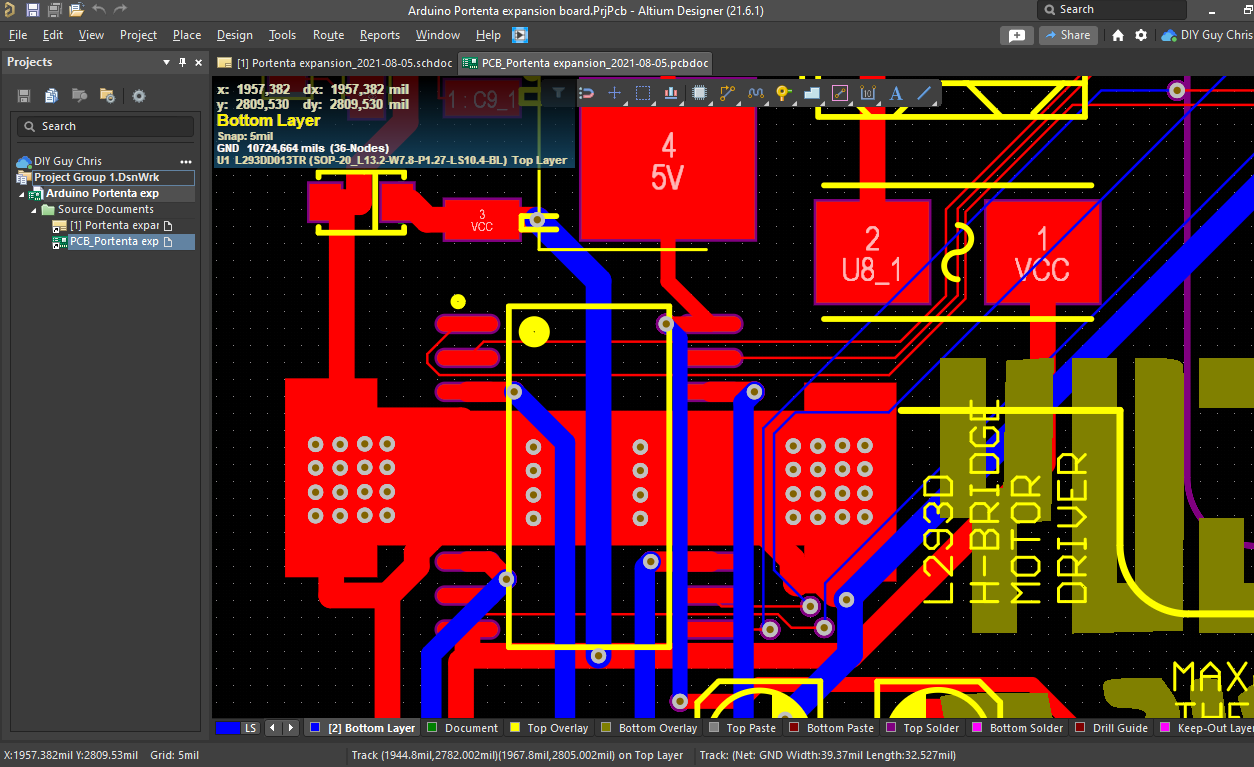
We still running Altium designer for this part too because this EDA environment include it all, you can just transform the Schem to a PCB and then perform the routing.
I arranged my componets inside the board outline area for a size of about 106mm x 58mm , compact and suitable to connect the Portenta H7 and to practice by exploring the circuit board components.
 I respected the header to header spacing to match the
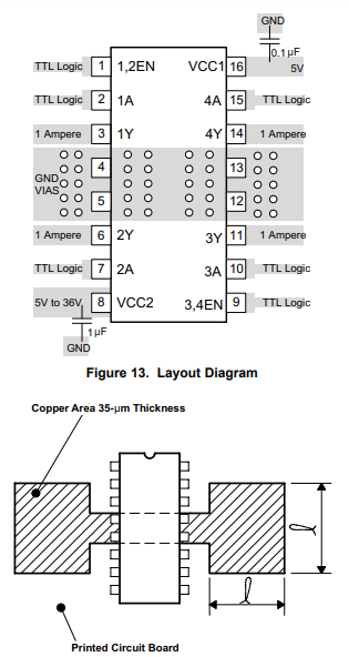
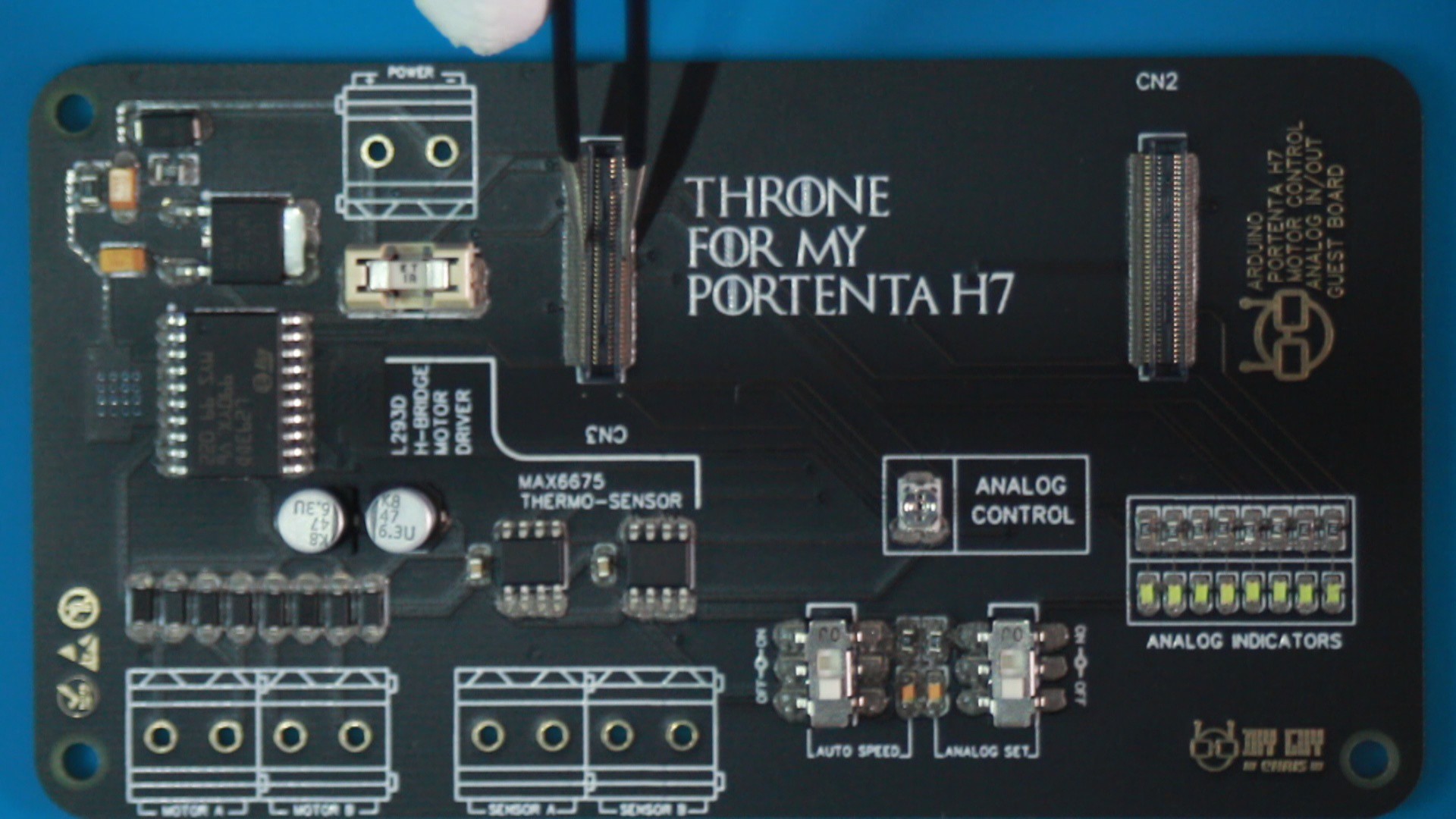
The final step on the designing stage is giving a cool name to my board :
Throne board for Portent
That's the name :)
It Is Time to Assemble
After genrating the GERBER files for PCB manufacturing, all what we need is submitting the files to a PCB manufacturer and wait for the boards to come.
As always The PCB ordering is the easiest step ever when it comes to JLCPCB ordering webpage, it is all detailed out there, just upload the GERBER files that you can download from the files source below, then set some PCB manufacturing paameters like the PCB thickness and color, I selected the black soldermask color for my Throne board to match the "Portenta Family".

I also ordered the PCB related Stencil to make the assembly easier for me especially with the tiny parts footprints that I used in my design.


I give five stars for JLCPCB for their good work and fast delivery.
I ordered the components from Farnell Electronics and you can download the BOM file that has all the necessary parts details if you want to order it too.
Now we have all the ingradients ready, it’s time to assemble. I used a low temperature solder-paste (Chipquik SMDLTLFP10T5) to assemble my electronics parts using the hot plate, I don’t recommend the use of a solder iron or soldering hot air gun because the plastic housing of these HRS connectors could be easily damaged.
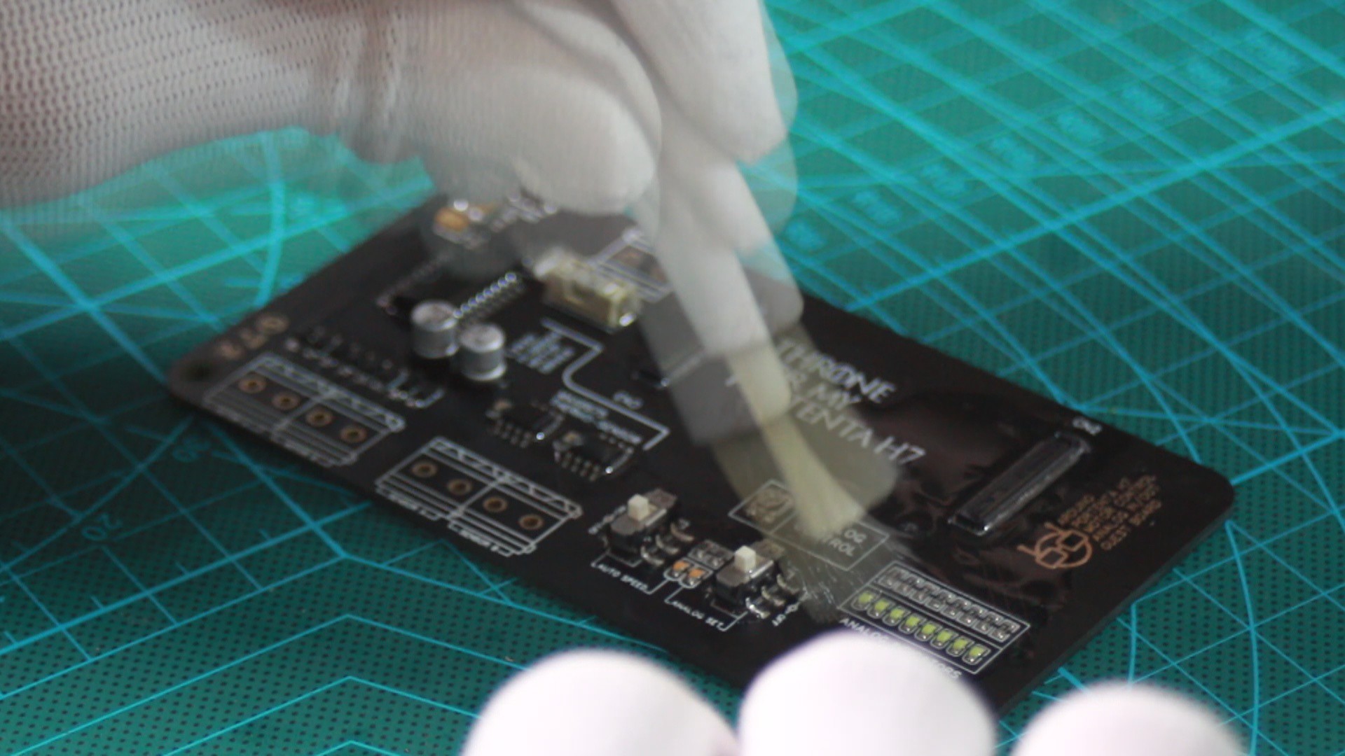
After finishing the assembly do not forget to clean your board with some flux removal.
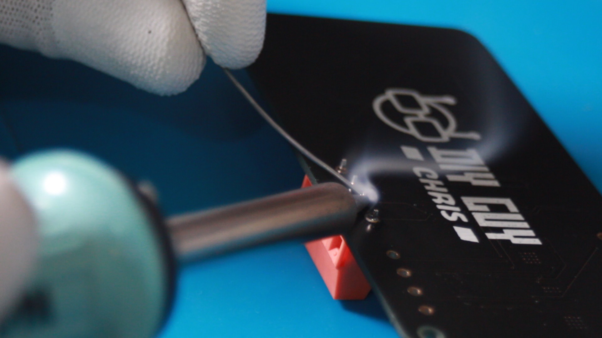
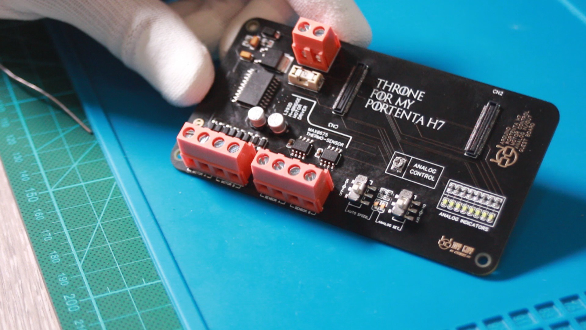
I soldered those beautiful screw headers to the sides of the board where I can plug in the external power supply and the sensors and actuators, those terminals give an attractive looking to my Throne board

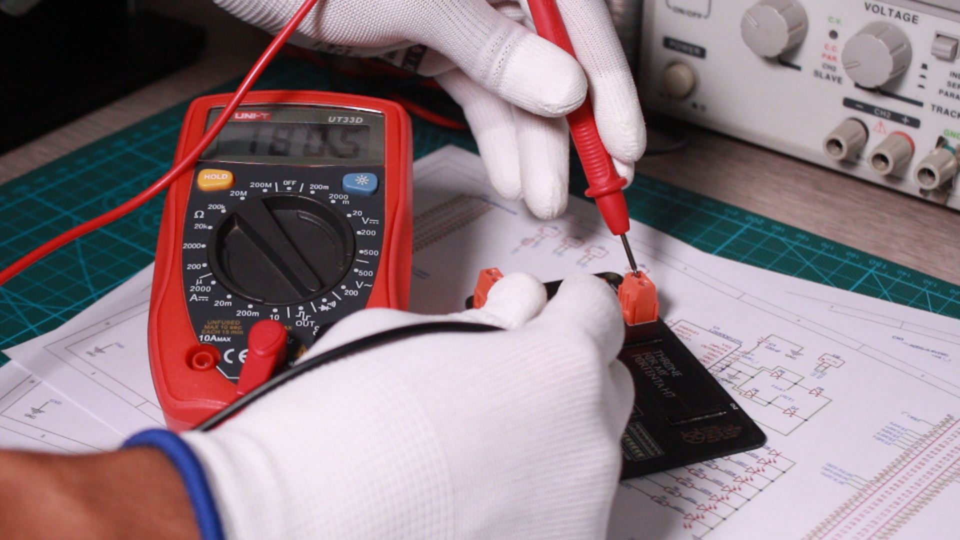
Let's Play With It Now
I know that you can't wait to place the Portenta on the Throne, but don't harry! just one more step is needed, I must make some short circuit tests to ensure that we didn’t left any shorted path. I also plugged external power supply to measure that the Portenta will receive the power through the external power source without problems.
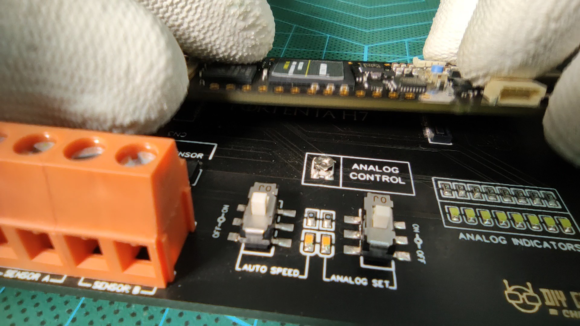
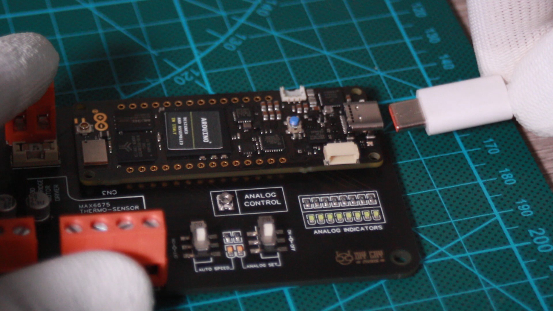
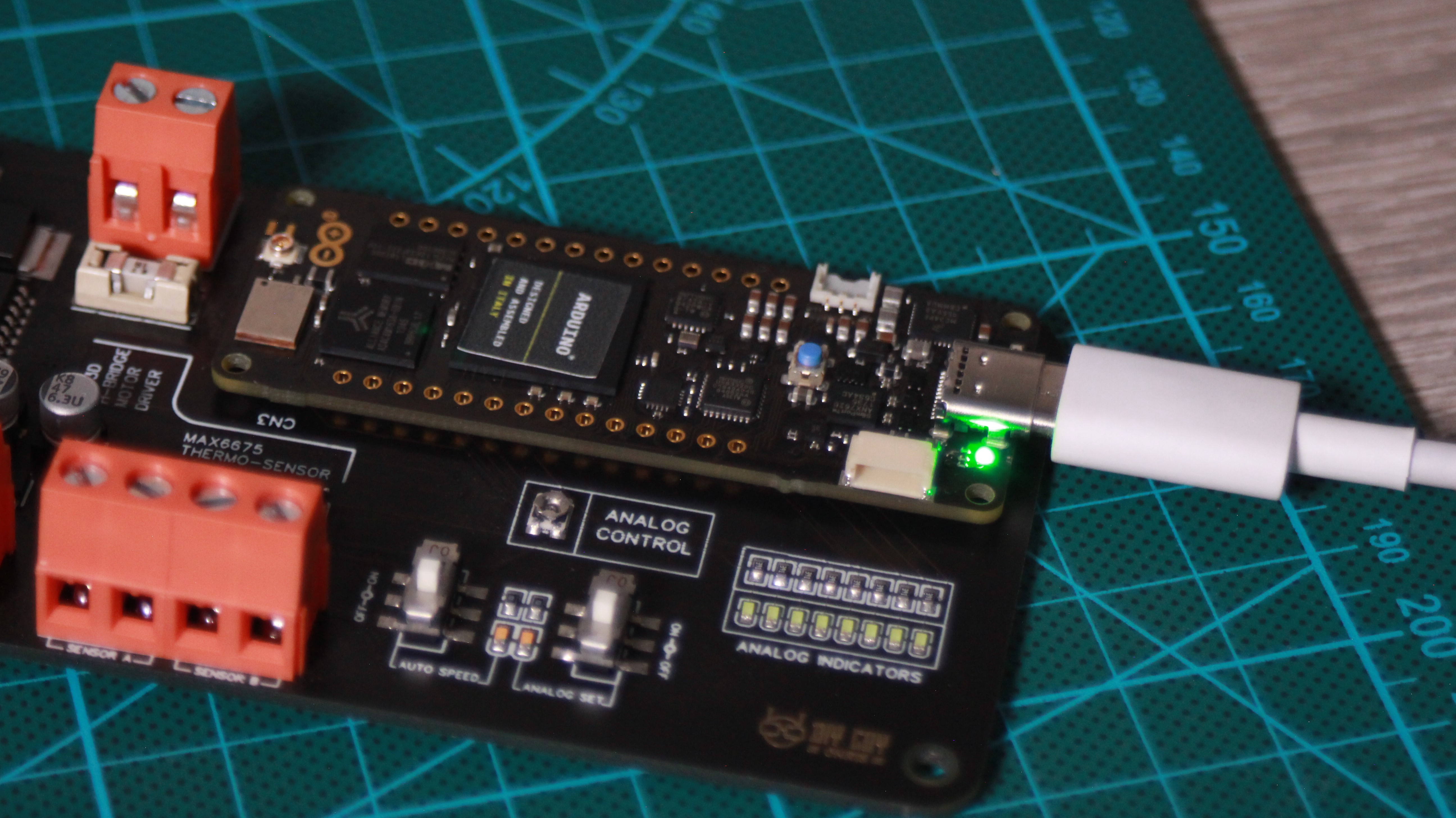
My Throne board is ready now to receive the guest, as you can see guys the Portenta fits very well on the Throne and it has a charming looking,
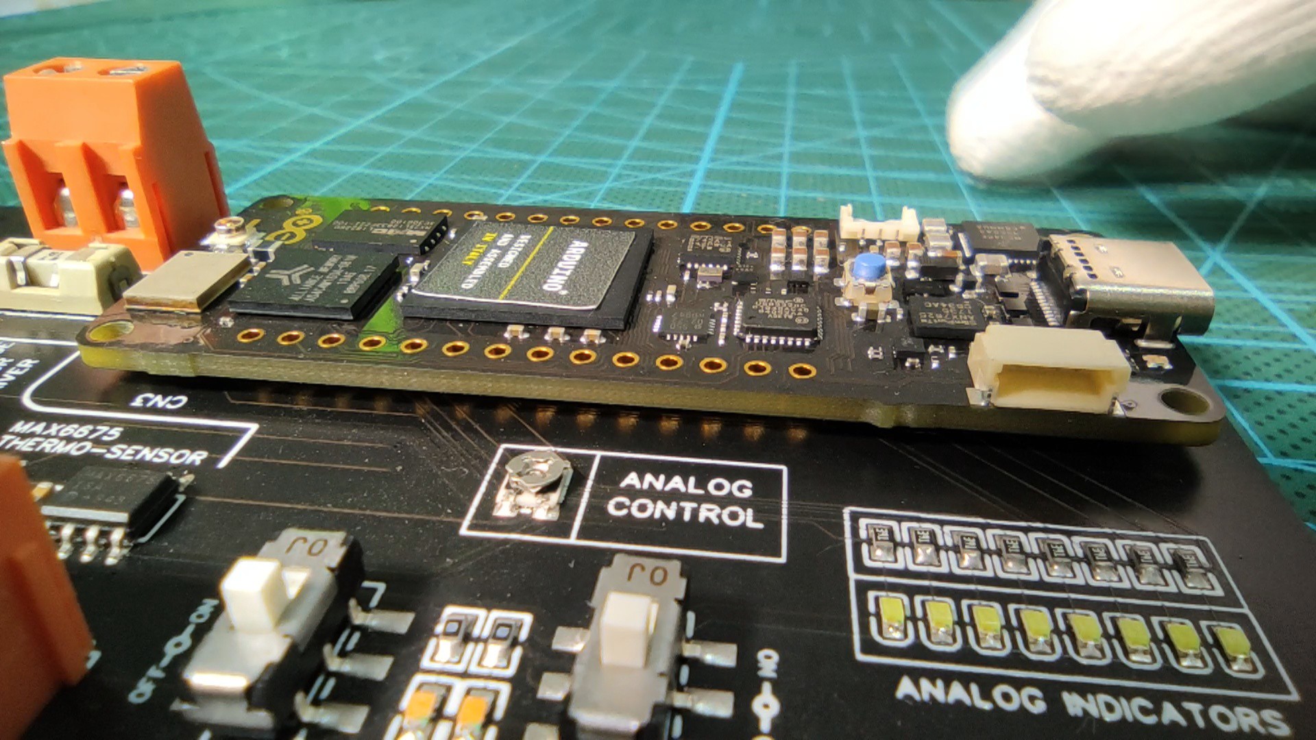
Now we move straight to the software part.
I run my Arduino IDE, no configuration needed for the latest version so I directly uploaded a blink LED sketch to my board. Oh hey! you will need a USB Type C cable for this Arduino board.
I just noticed that the access to the board GPIOs is not as same as the other Arduino boards because you need to call for the pin action by specifying the Port name and pin Number, as an example the Digital pin 0 is not D0 not even just 0 but it is the 15th box of the "H" Port register that's why it is labeled as PH15 and in order to use it with Arduino APIs it has to be written as PH_15, taking the example of a digitalWrite function it will as follow : digitalWrite(PH_15, Status) ; where Status could be a HIGH or LOW logic level
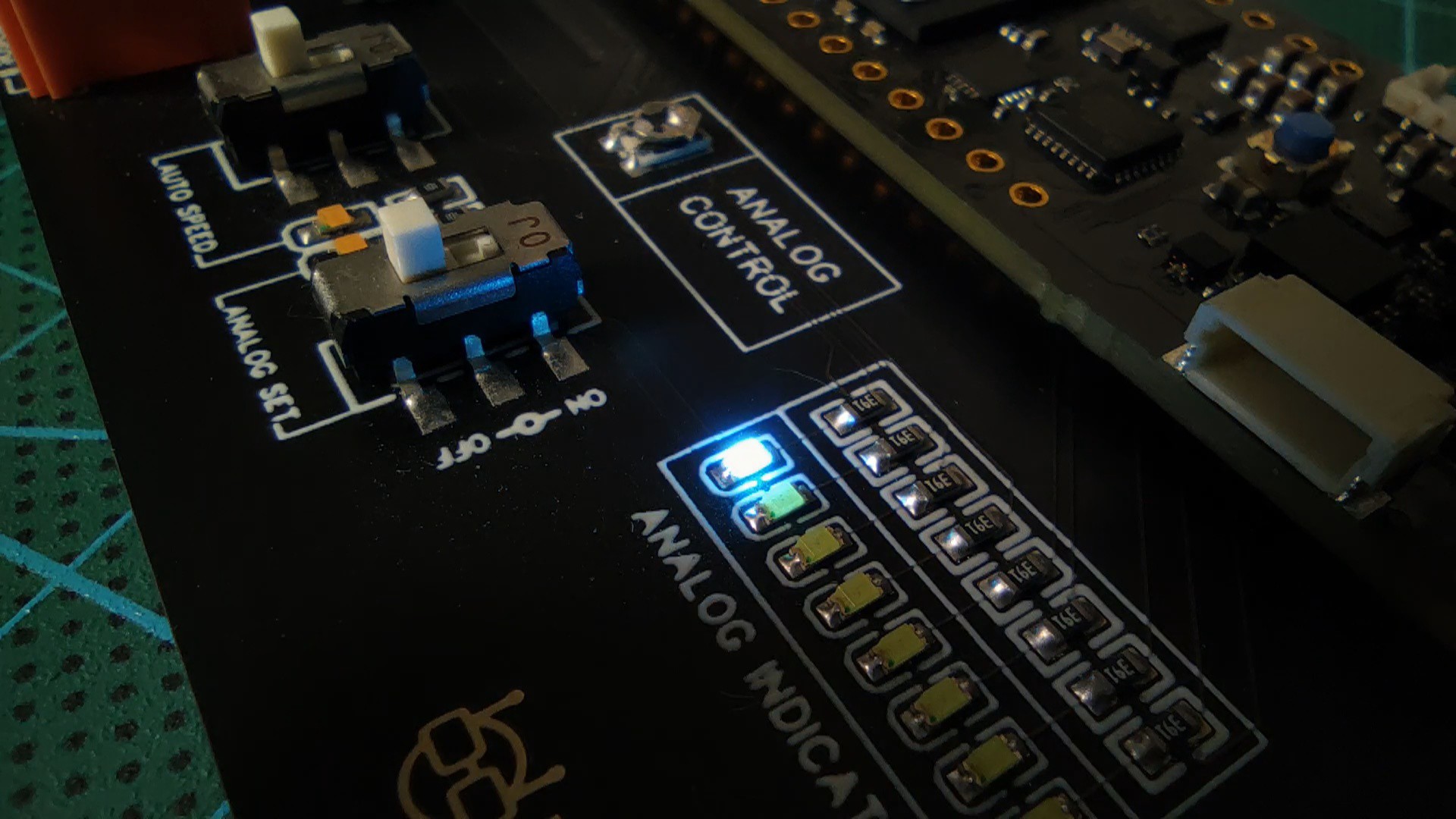
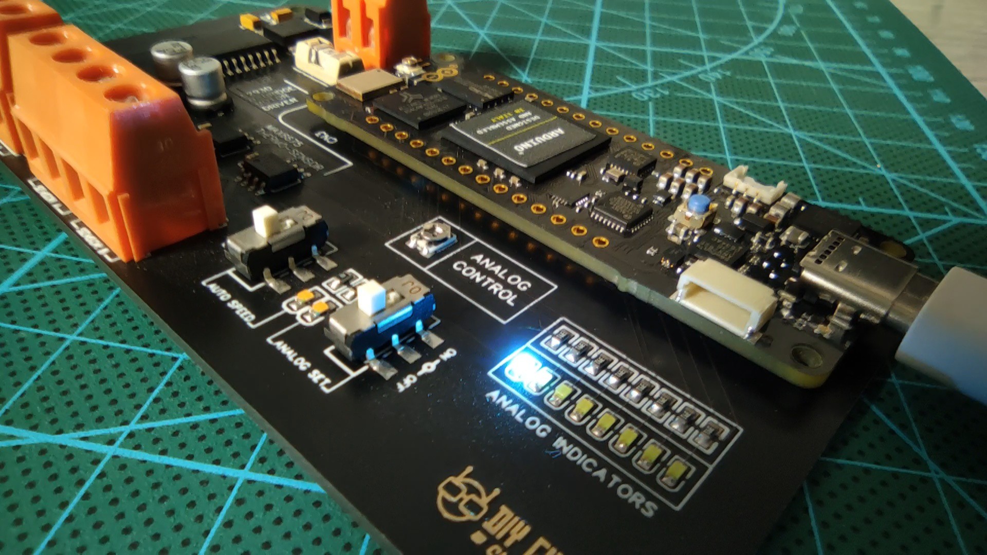
The blinking code is the classic one that we used to use to test Arduinos and I got the desired blinking frequency on one of my Blue ice LEDs of the Throne which confirms that the access to the Portenta board ports has been successfully achieved.
This was the first part of the Throne board Tutorials, more other tests will be posted in the second part of this cool project so stay tuned.
One last thing make sure that you are doing electronics everyday.
It gladdens me for having you company, I'm Chris and I Thank you for reading!