Background
The idea behind this robot is to create a cheap, small and simple robot platform that has all the basic features in a fixed basis and to which additional features can easily be added. Making the basis cheap, small and simple allows the robot to be built in large numbers, for use in cooperative and swarm robotics.
This is planned to be a long term project, over several years, to be expanded upon and adding features both through new hardware and software algorithms. The first phase is to develop the robot base, both the drive mechanics and control software as well as the basic collision sensor acquisition and tuning.
There are a few modules already planned, with some in early design phase:
- A main control and communication board (probably using a STM32F4 or STM32H7 with bluetooth and NRF24L01+ radios)
- A sensor board for the top with IMU and a couple of ToF sensors, forming a cheap low resolution LiDAR
- A dedicated processing board using either a FPGA or a SoC, or a combination of both
Besides the hardware there are many software algorithms to be implemented and tested, under others:
- Integration with PC software, including ROS (python library) and maybe Unity (C# library) with a costume environment
- Localization, and SLAM, with simple sensors, without high resolution LiDAR
- Path planning with different path finding algorithms (A*, RRT, RDT, FM)
- Cooperative and swarm robotics
Hardware
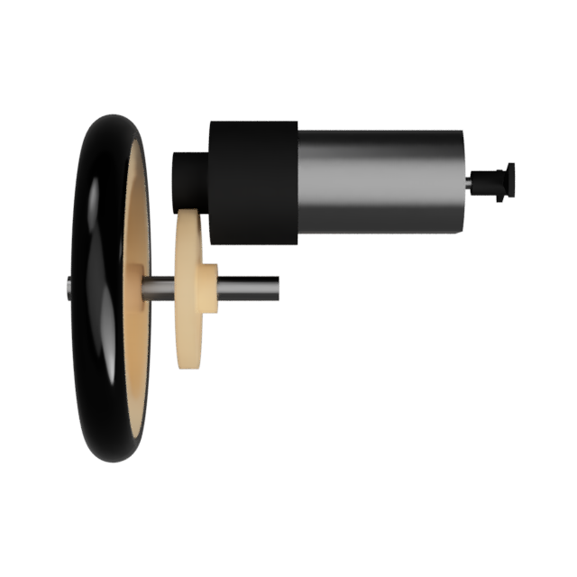
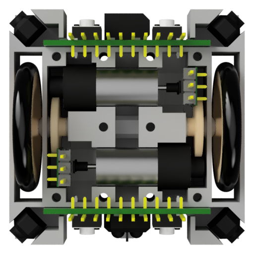
The robot basis is built around the drive-train which is powered by two M10 Brushed Motors with planetary gears and a plastic leaf for the encoder. The output of the planetary gear is a 11 tooth modulus 0.5 gear that drives a 24 tooth gear on a axle that is connected to a wheel. The wheels are made out of a 24mm diameter plastic pulley with a 26x3.1mm outer diameter O-Ring as a tire.
 This whole drive assembly is hold in place by two 3D printed parts, the Drive Bottom Holder where all is mounted into and the Drive Top Cover which closes the mechanics off. The Drive Bottom holder also has place for Collision Sensor Boards, in the front and back, as well as a place for two Motor Encoder PCB, one for each motor. On the bottom of the Drive Bottom holder there are mounting places for plastics skids, used to make the robot stable by adding a third, and forth, contact point with the ground.
Each Collision Sensor Board holds two contact collision sensors, buttons, and three IR reflective collision sensors (TCRT500). The PCB slides into place and connects to the Motor Drive PCB for acquisition and control. The two Motor Encoder Boards each use a IR reflective collision sensor (ITR8307) together with a voltage comparator to output a pulse each time the motors plastic leaf passes in-front of it.
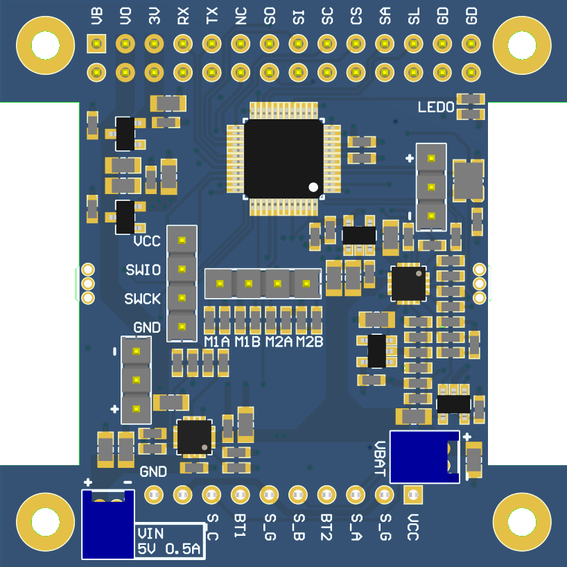
The Motor Drive PCB is the heart and brain of the Mini Cube Robot platform. It has at its core a STM32F103C8 MCU that controls the dual H-Bridge motor driver, STSPIN240, acquires all the sensors and does the interface with the rest of the robot, future modules, over an expansion header with I2C, UART and SPI interfaces. The Motor Drive PCB also is the power supply for the robot through a 1S LiPo that is connected to a battery charger and manager IC, the BQ24230. The Motor Drive Board provides both raw battery voltage rails as well as a dedicated 3V3 rail on the expansion header for other modules.

This project is in very early development phase and many things will change over time. All the current files for the PCBs, Schematic and Gerber files, and the 3D printed parts are freely available to download bellow.
More in-depth information can be found on the website, also more frequent updates what is being worked on on this and other projects are published on twitter.
 NotBlackMagic