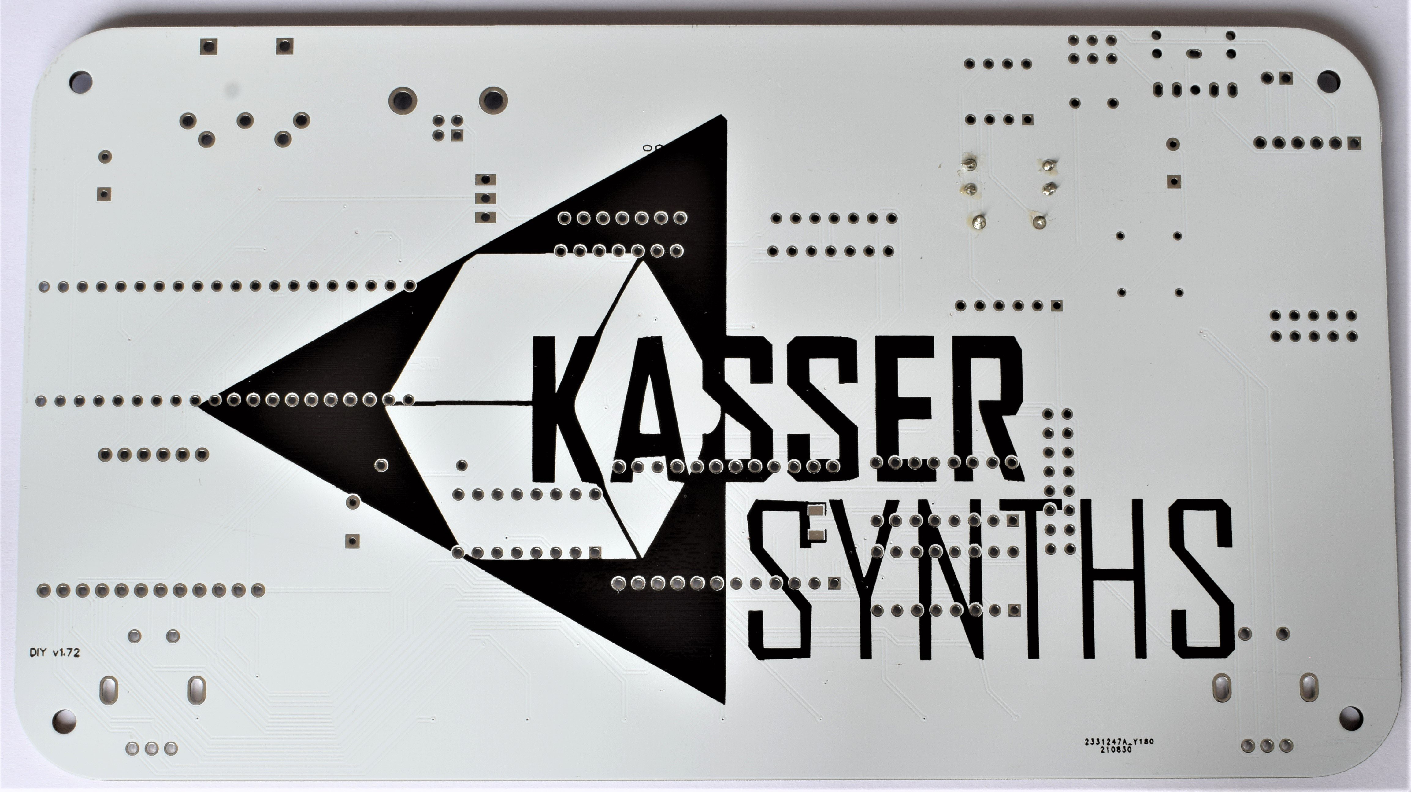
Close
0%
0%

DAFM synth BLASTER YMF262 (OPL3) - DIY kit

DAFM Synth is a FM multitimbral synthesizer serie based on mythical YAMAHA chips used for home consoles, arcades and 80s PCs sound.

Similar projects worth following
Now the DAFM synth BLASTER YMF262 (OPL3) has been redesigned as a DIY friendly kit. This is a nice project that comprises soldering of through-hole components.

This kit can be found on Tindie:
https://www.tindie.com/products/24963/

Assembled version with case and knobs can be found here:
https://www.tindie.com/products/24474/

What is it?

Sound synthesis through Frequency Modulation (FM) allows to obtain unique sounds that defined a whole musical generation during the 80's and 90's.

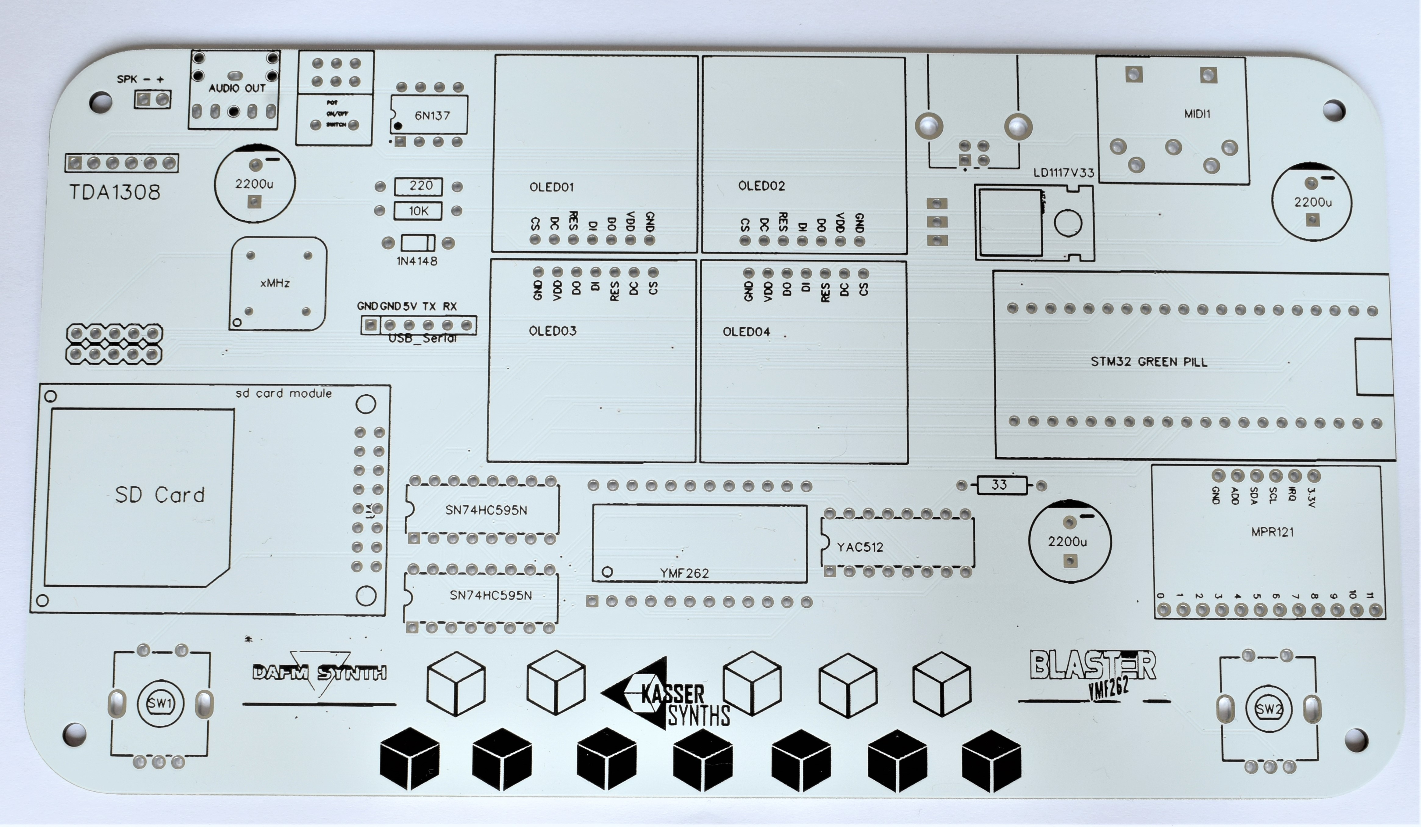
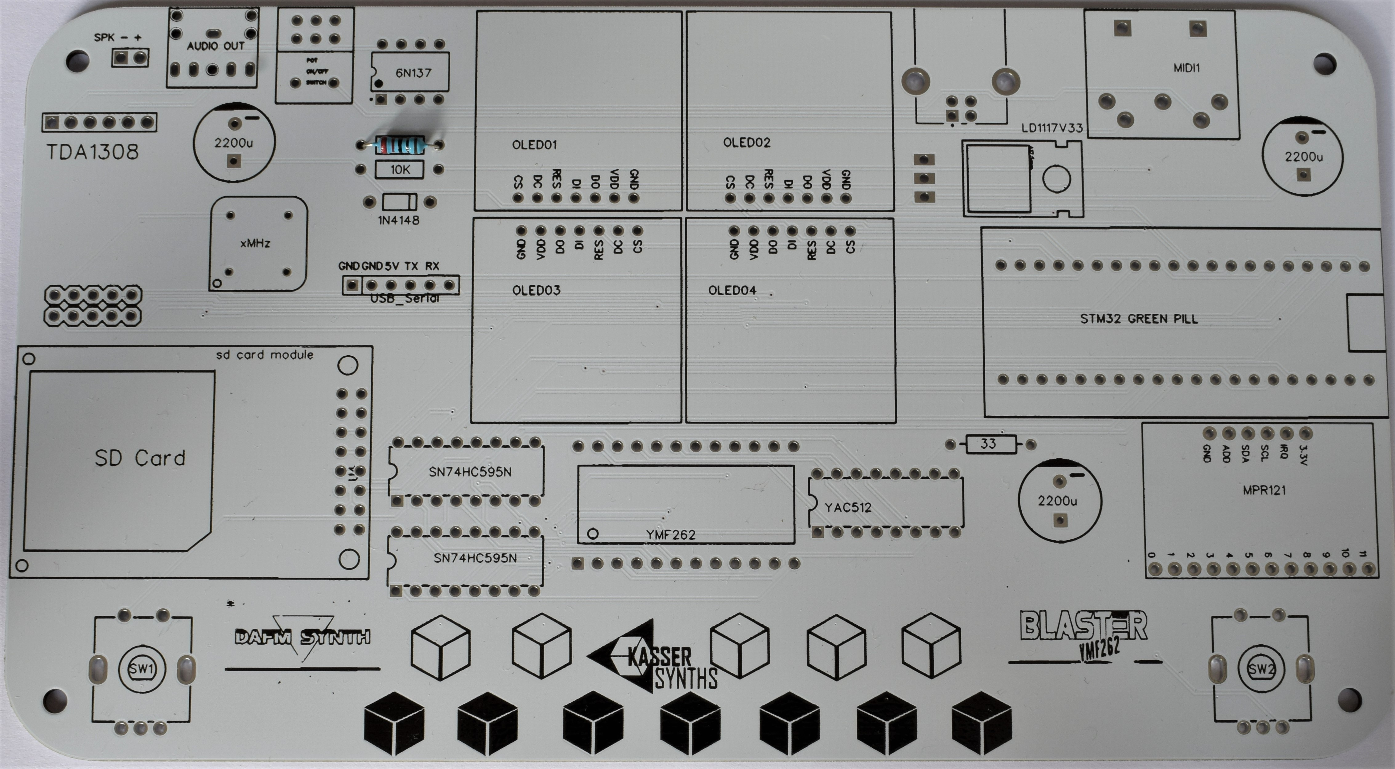
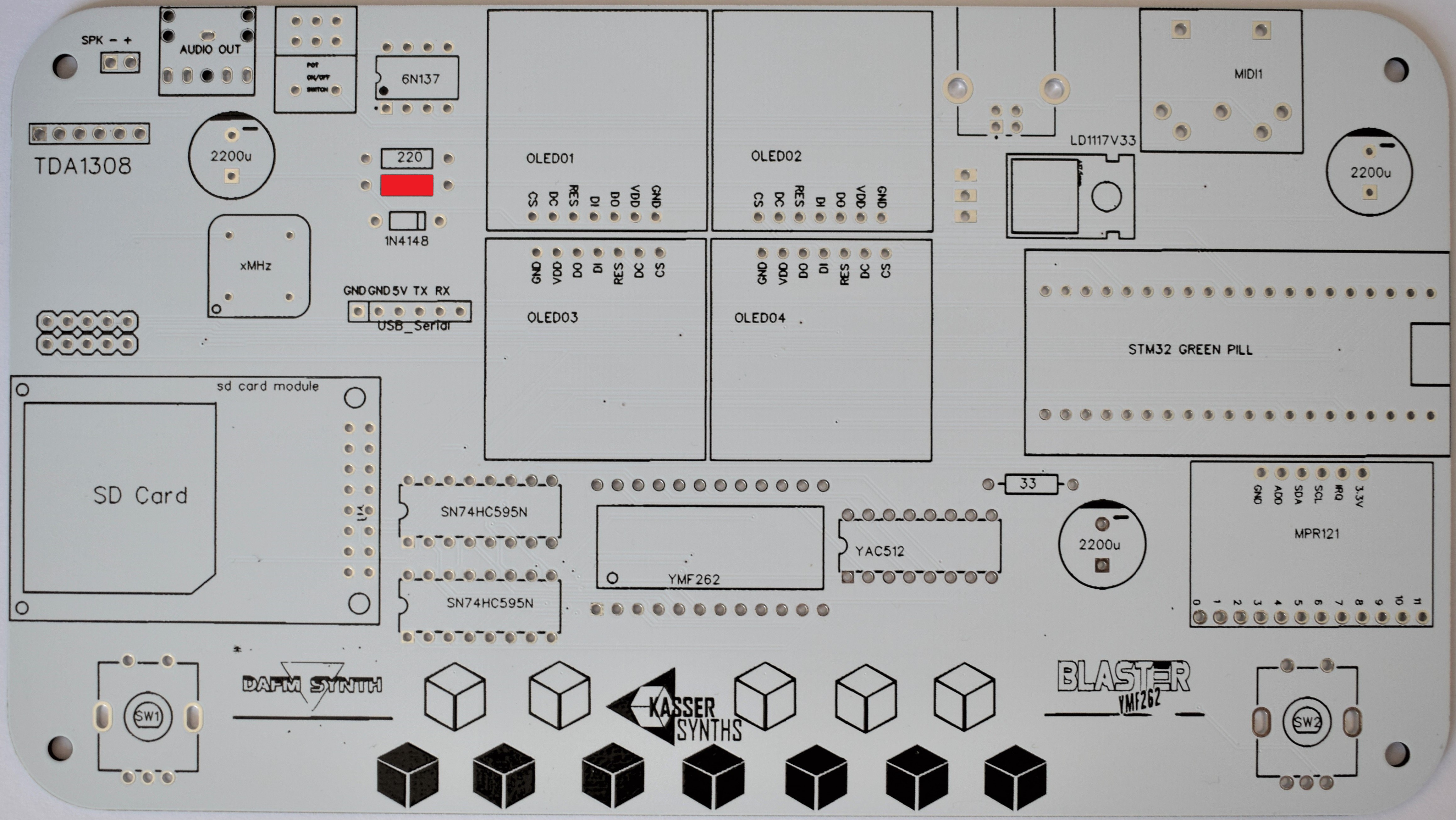
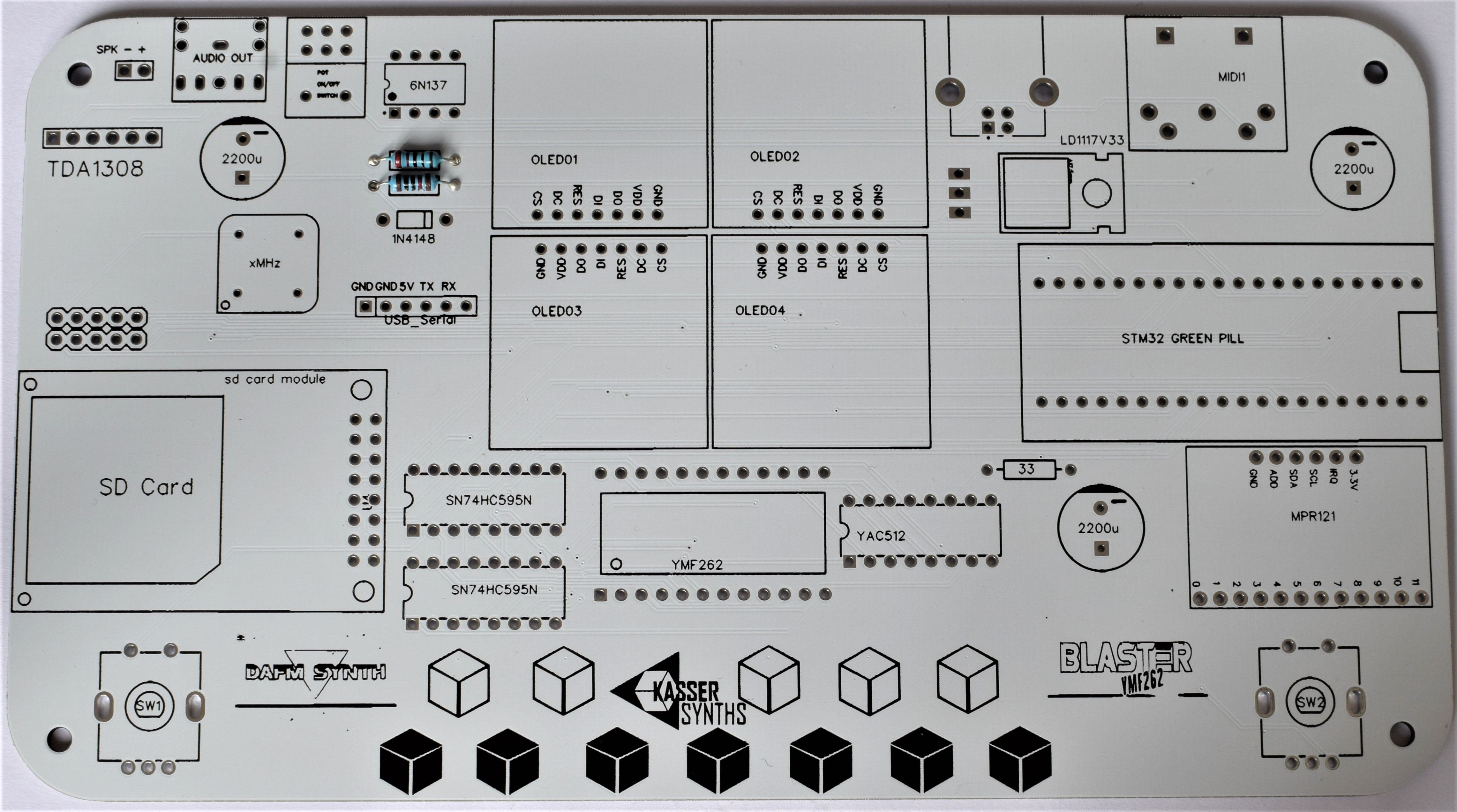
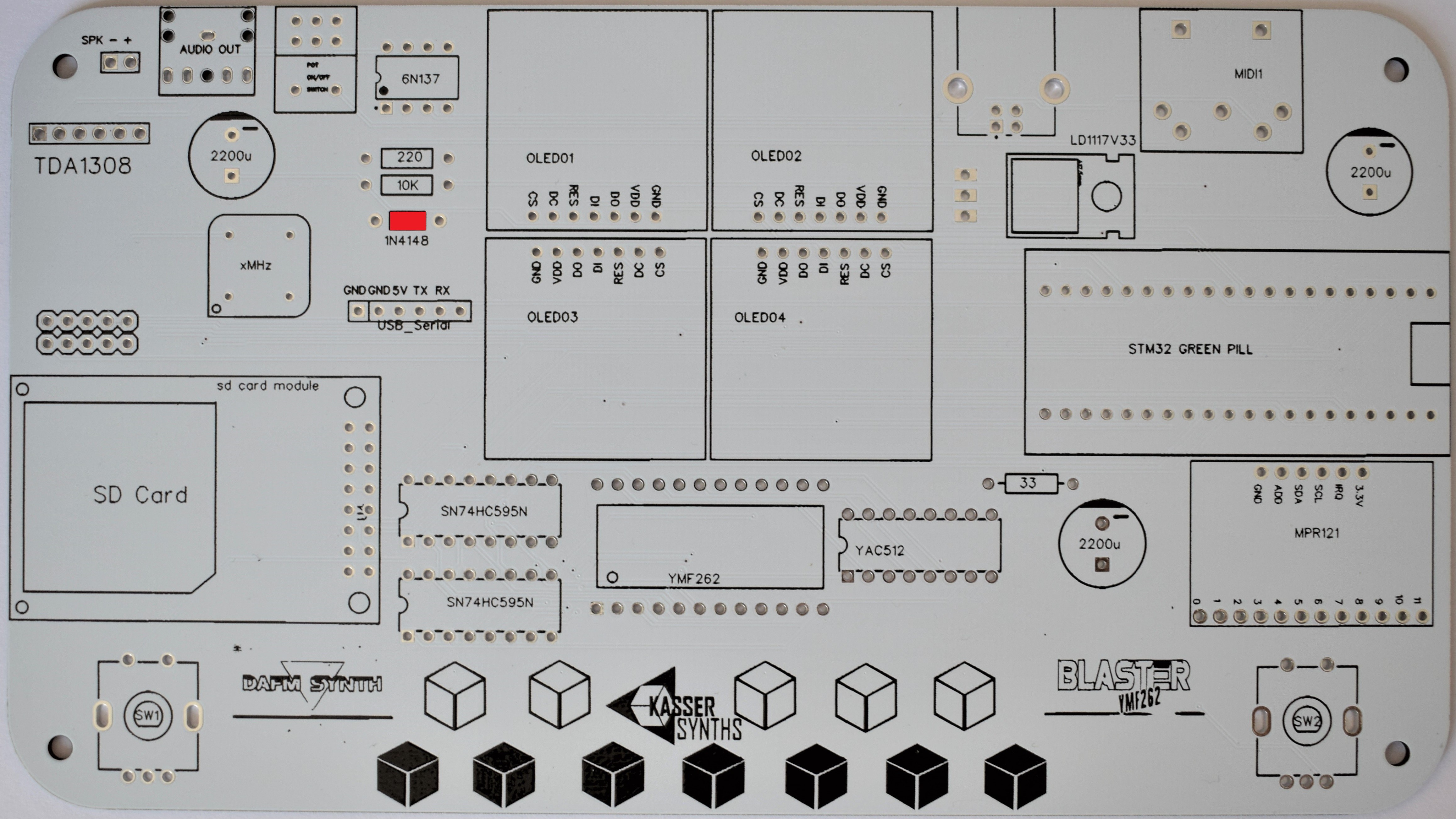
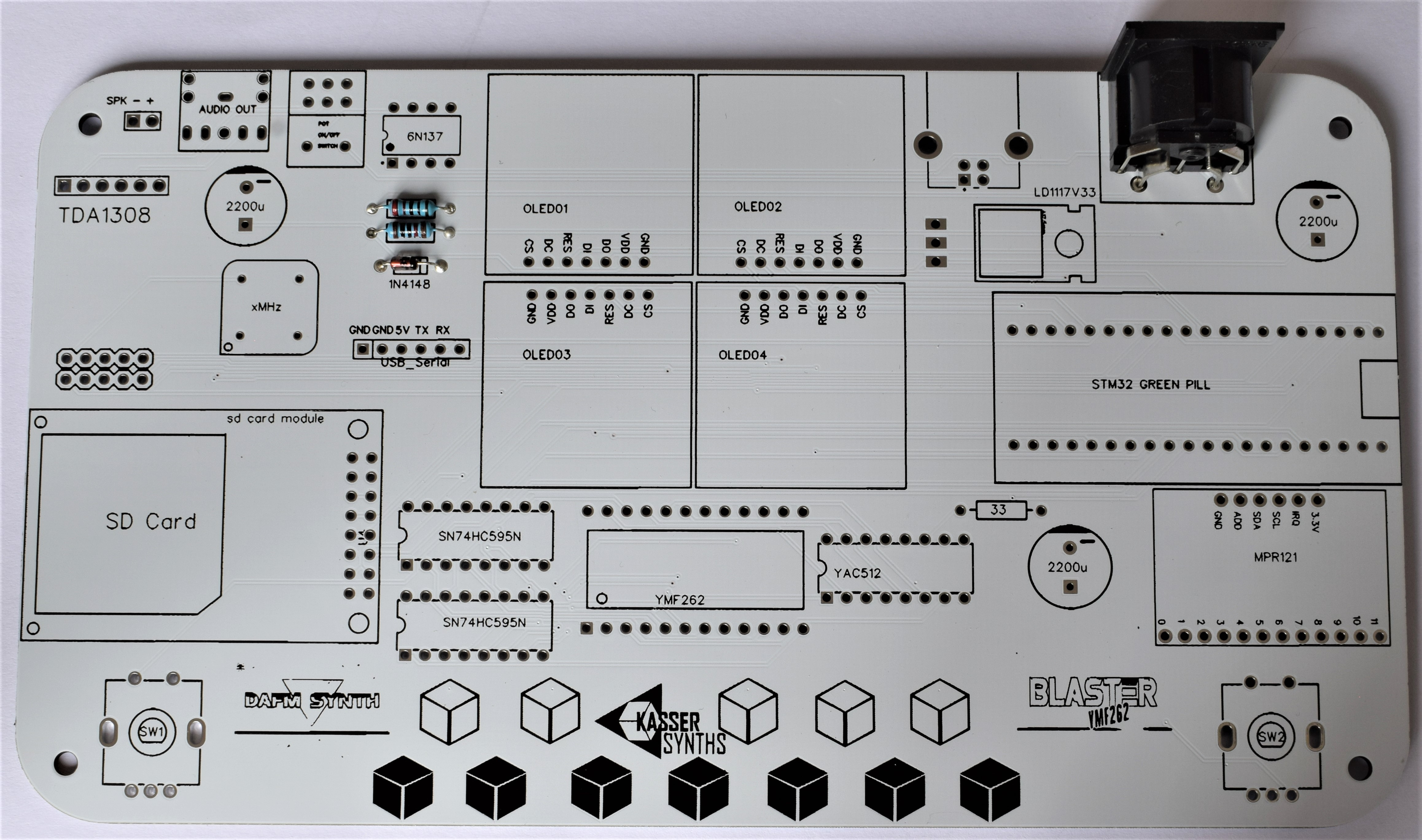
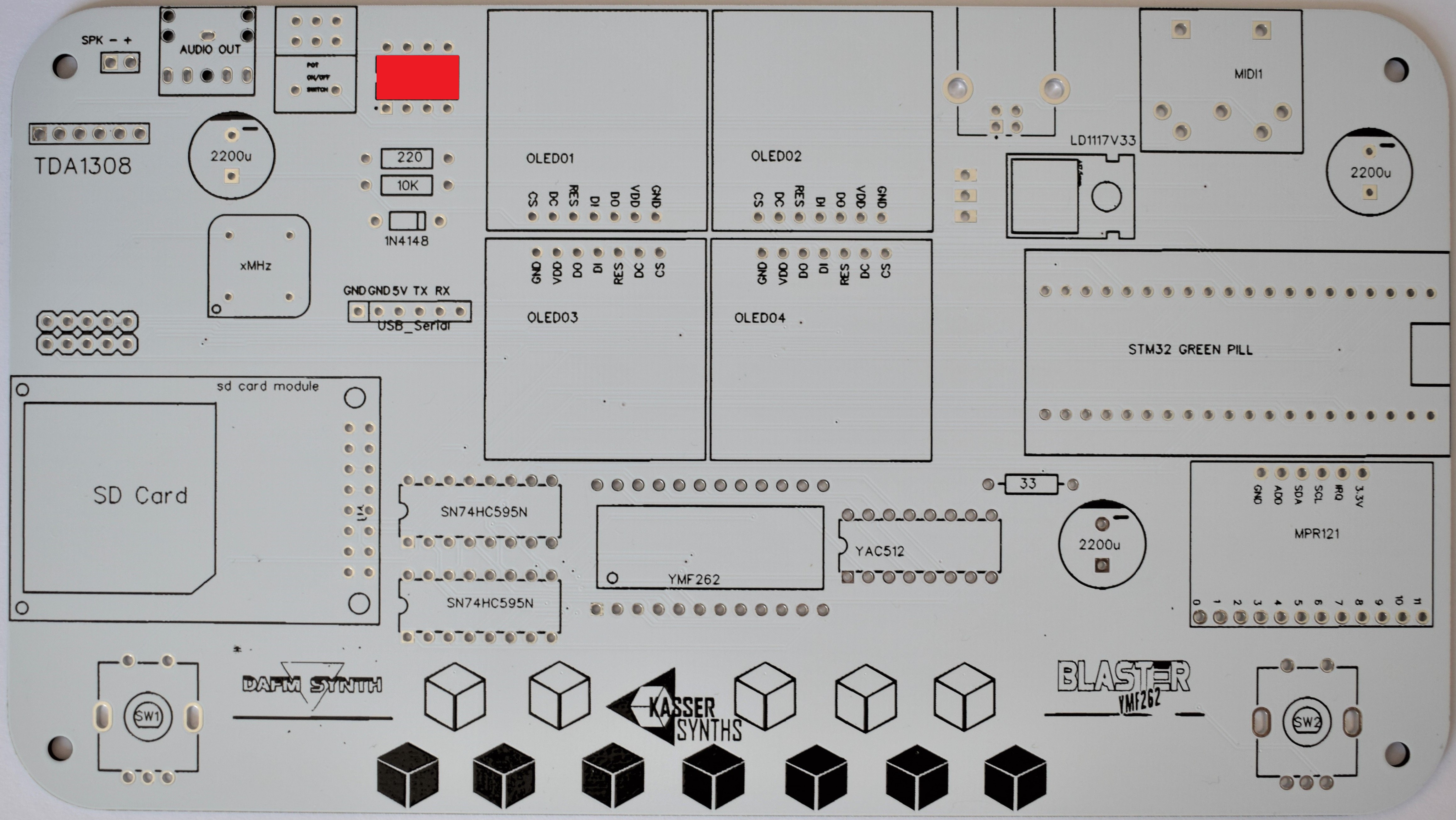
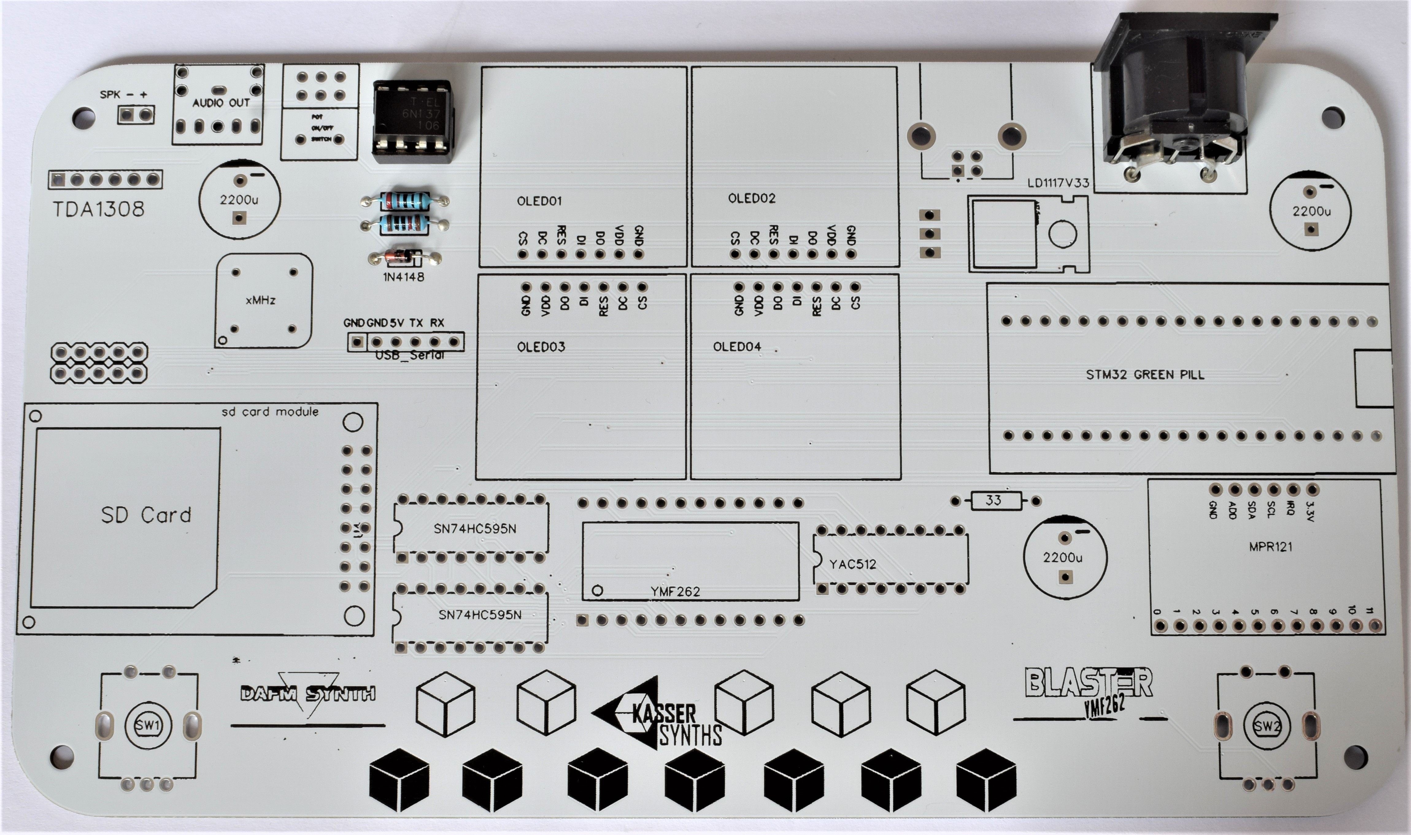
The model BLASTER uses the YMF262 (OPL3) Yamaha chip that was employed in many sound cards, including the popular Sound Blaster Pro 2 and the Sound Blaster 16 ASP.

Why did you make it?

This synthesizer is the perfect mix for lovers of retro video games, and makers who want to introduce themselves in the musical experimentation.

Includes the 128 General Midi 4-OP instruments designed by The Fat Man and used in 90's PCs videogames like Doom; Descent; Tyrian; The Lost Vikings; Heretic; Hexen, Ultima Underworld; Day of the Tentacle; Dune; Wing Commander; Another World; Syndicate; Lemmings and Indiana Jones & the Fate of Atlantis. These presets can be found in Bank 0. Bank 1 is used for loading up to 128 presets from the SD Card. Check the Datasheet below for the details.

All the parameters that defined these presets in the YMF262 chip can be controlled through MIDI CC messages. Check the Datasheet below for the MIDI CC implementation chart.

What makes it special?

The YMF262 has six channels with four operators per channel. The operators can interact according to four different algorithms. Attack-Decay-Sustain-Release (ADSR) envelopes, frequencies and low frequency oscillators (LFOs) can be modified to obtain the whole range of FM sounds.

The YMF262 chip is accompanied by the YAC512 stereo chip that allows converting the digital signal into clear and clean analog sound. Having the separate DAC allows the DAFM synth BLASTER to output a louder and cleaner sound.

The synthesizer is operated through 2 rotary encoders and has a complete menu that is shown in 4 blue OLED displays. Thanks to the beautiful tactile keyboard of 12 notes you can try the different patches as they are created. There is also the possibility of changing the octave and thus test the full sound spectrum of the Yamaha chip. Once created, the presets can be saved in the RAM memory or in an SD card as OPLI files that can be opened with instrument editors like the OPL3 bank editor.

The stereo sound output is 3.5 mm audio jack, has a MIDI input to connect a keyboard, sequencer or any MIDI instrument and can be powered with a USB Type B cable (5V).

Adobe Portable Document Format - 175.48 kB - 03/18/2023 at 20:31

Preview
Download

Adobe Portable Document Format - 333.13 kB - 03/18/2023 at 20:27

Preview
Download

  • 1 × PCB DAFM synth BLASTER YMF262 PCB
  • 1 × 220Ω Resistor Resistor for MIDI Input Circuit
  • 1 × 1N4148 diode Diode for MIDI Input Circuit
  • 1 × 6N137 Optocoupler Optocoupler for MIDI Input Circuit
  • 1 × 8 pin IC socket IC socket for 6N137

View all 26 components

  • 1
    Warm-up: Be ready for soldering!

    Please be careful with soldering. Too cold and you will get cold joints with false contacts. Too hot and you could destroy the soldering pad and break connections. Try to use flux to help you. Use the right solder tip, the right iron and the right temperature for your soldering wire.

    Here you can find a tutorial for through hole components soldering:

    Through hole components soldering tutorial

    If you have any performing issue after finishing soldering, check the TROUBLESHOOTING part at the end of the list.

  • 2
    PCB Top

    We’ll populate only the top of the board – it’s the side with the KASSER SYNTHS and BLASTER YMF262 logos. Here’s a shot of the board for reference.

  • 3
    MIDI In

    220Ω x 1 (red, red, black, black, brown)

    Resistors are not polarized, so it doesn’t matter which way around they go in. Bend the legs into a staple shape,and fold the legs over once you’ve inserted them into the board.

    You don’t need to fold them over too much, it’s just so they don’t fall out when you flip the board over. It’ll make it easier to solder and snip off the legs if you don’t.

    10kΩ x 1 (brown, black, orange, gold)

    Solder and snip.


    Diode 1N4148

    The 1N4148 has a see-through glass body.  It is part of the MIDI input circuit. Solder and snip. Watch out, the diodes are polarized, so pay close attention to which side the line marking on the diode body goes – it’s marked with a thicker white line on the PCB.

    5 Pin DIN Connector


    8 Pin Socket

    It’s for the 6N137 optocoupler. The side the notch goes is marked on the board by a broken line on the ICs outline.

View all 13 instructions

Enjoy this project?

Share

Discussions

Similar Projects

Does this project spark your interest?

Become a member to follow this project and never miss any updates