First of all, apologies for the lack of activity. Turns out reverse engineering is not all fun and games: apparently there's a lot of hours of tedious and repetitive work to do (who would've guessed, lol). University work and a general lack of time (and motivation sometimes) doesn't help, but I'm still working on this and I'll eventually get there.
So, where's the project at?
Last time I was here I told you I bought a phone. Well, here it is, in all its faded glory:
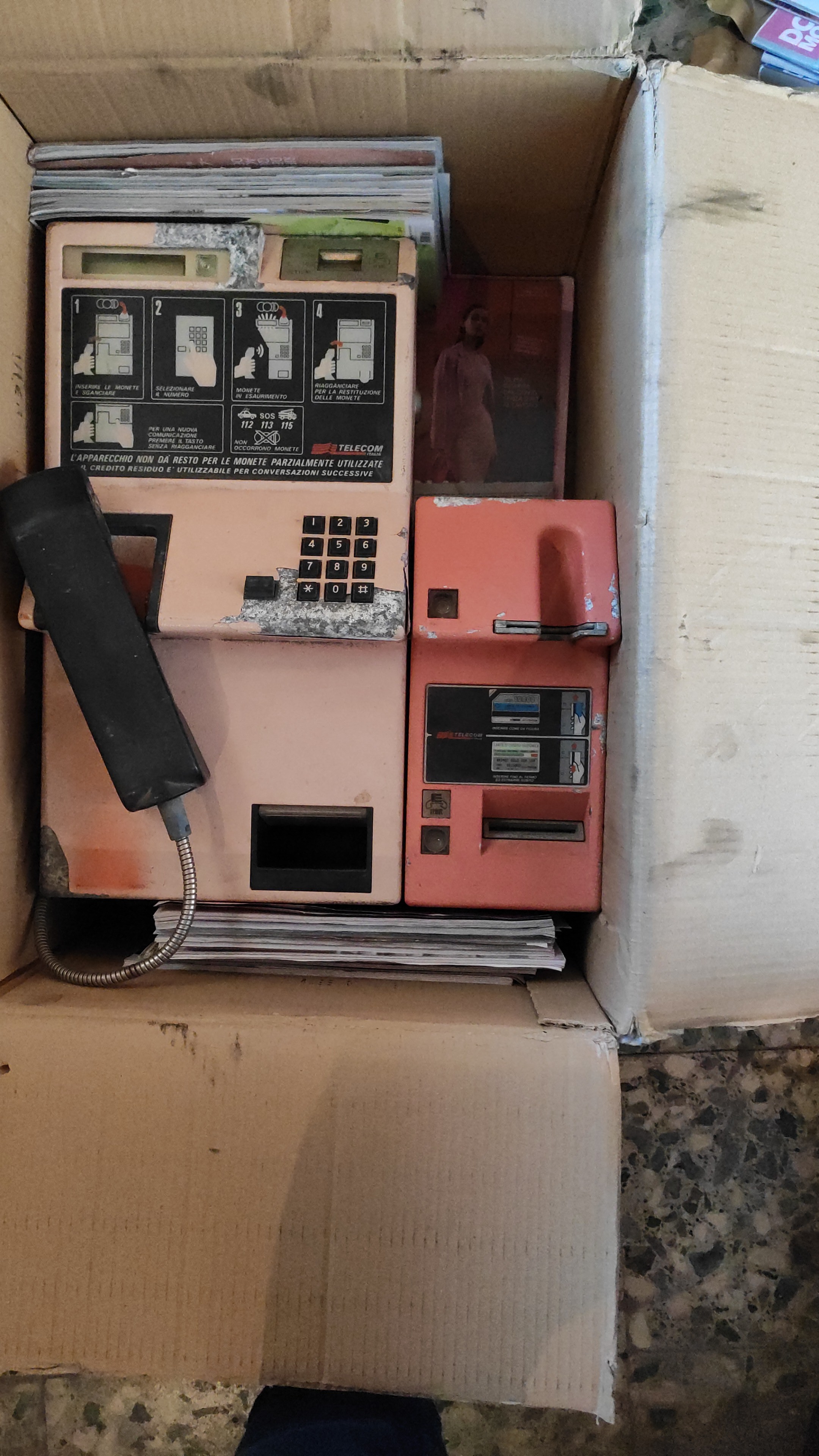
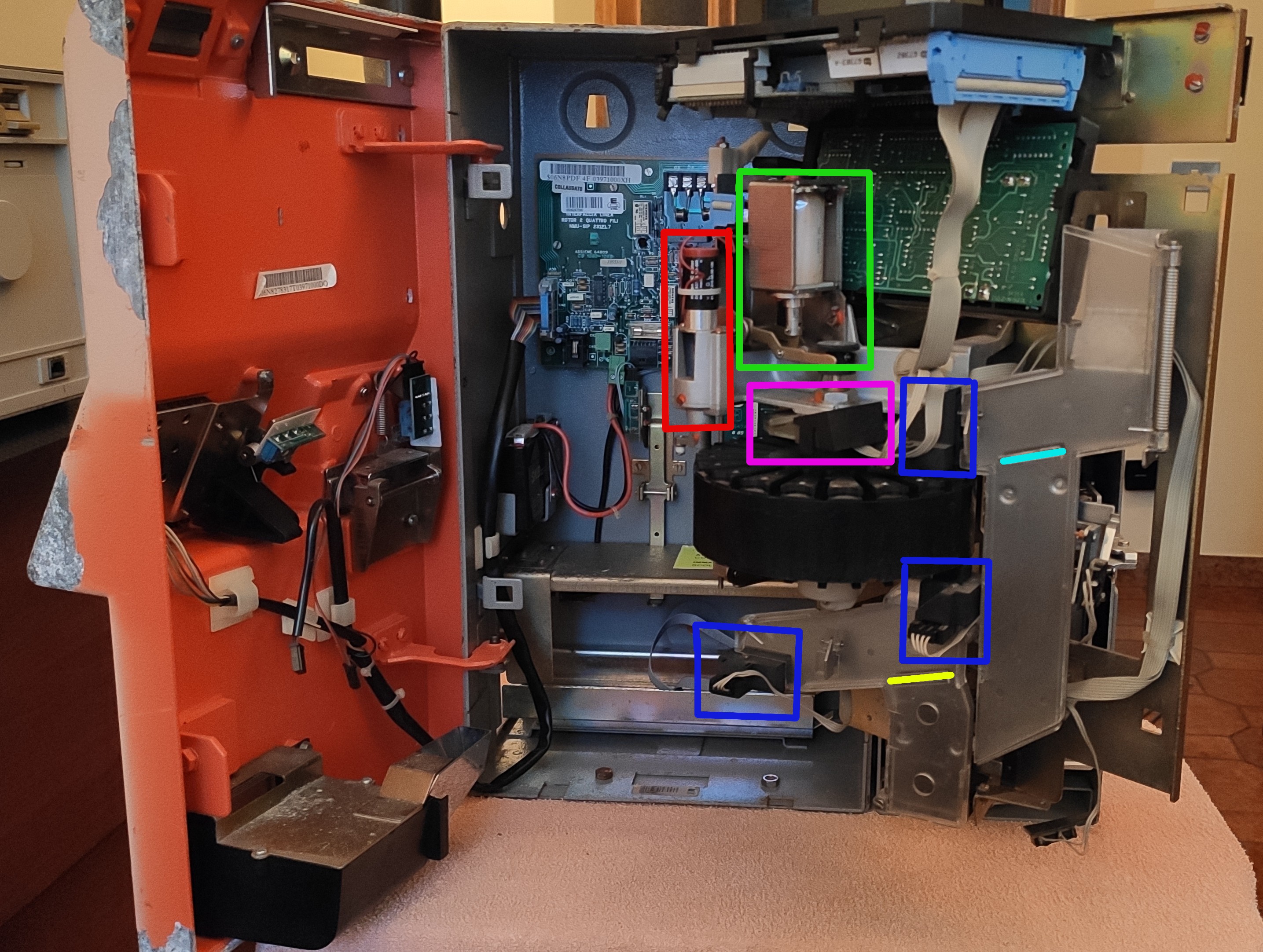
Looks bad, but it's complete and the electronics is in good condition. Here's the internals:
Sidenote: the whole mechanical section is on hinges and can be easily pulled out for maintenance, leaving you with this:
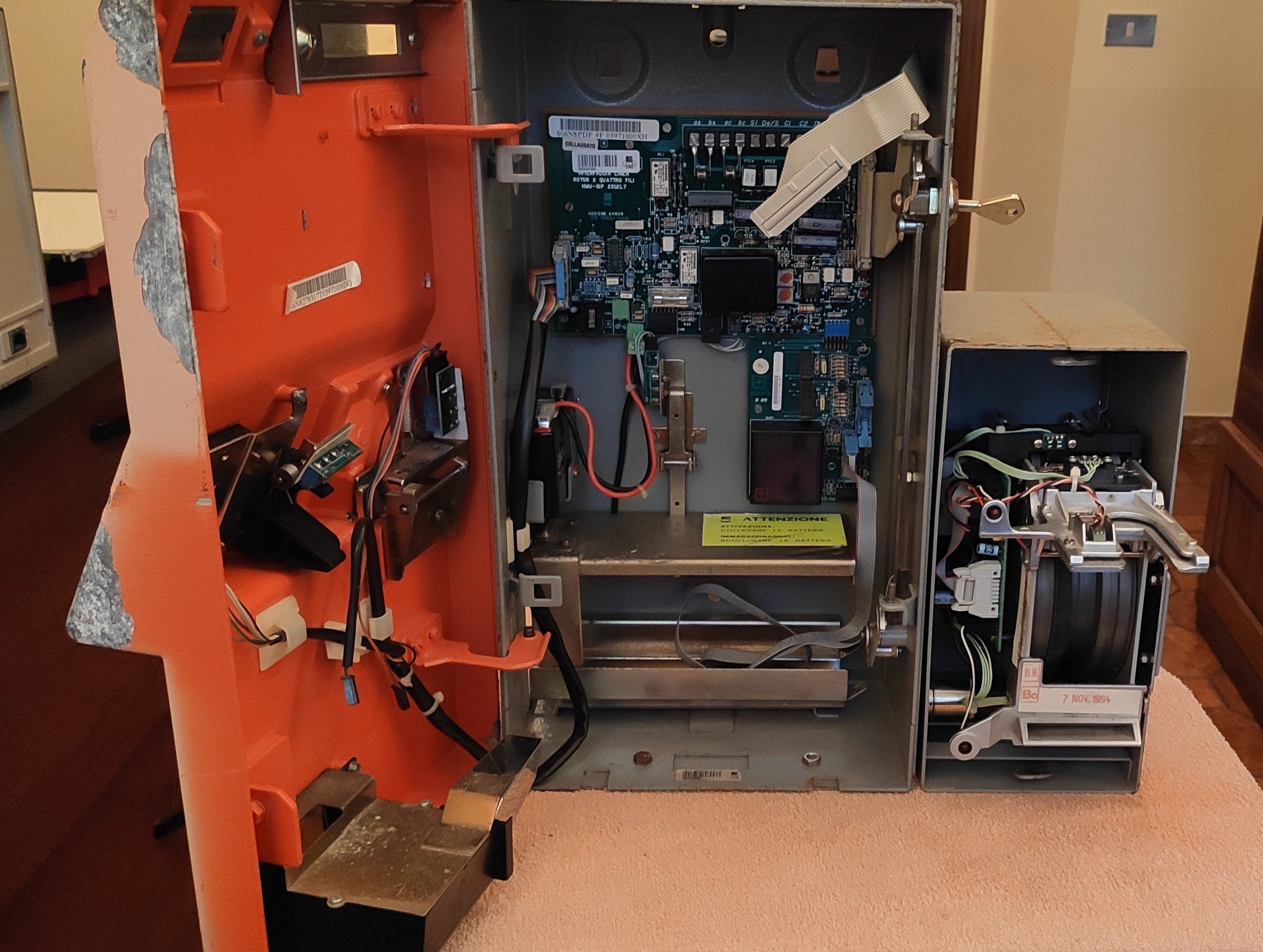
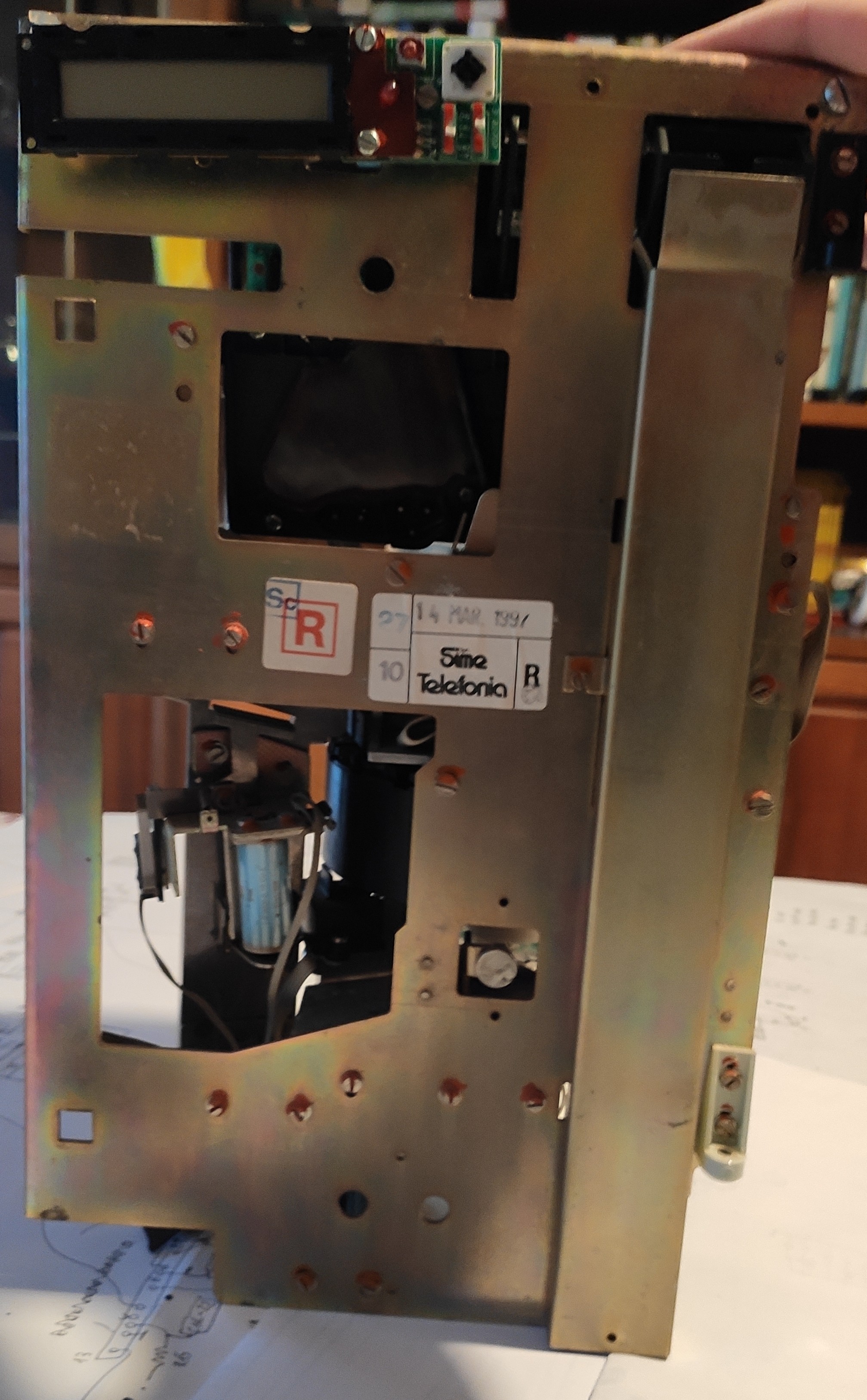
You can clearly see where the line interface, card reader interface and card reader module go. Here's the mech by itself:
So, how does all that mess of parts work?
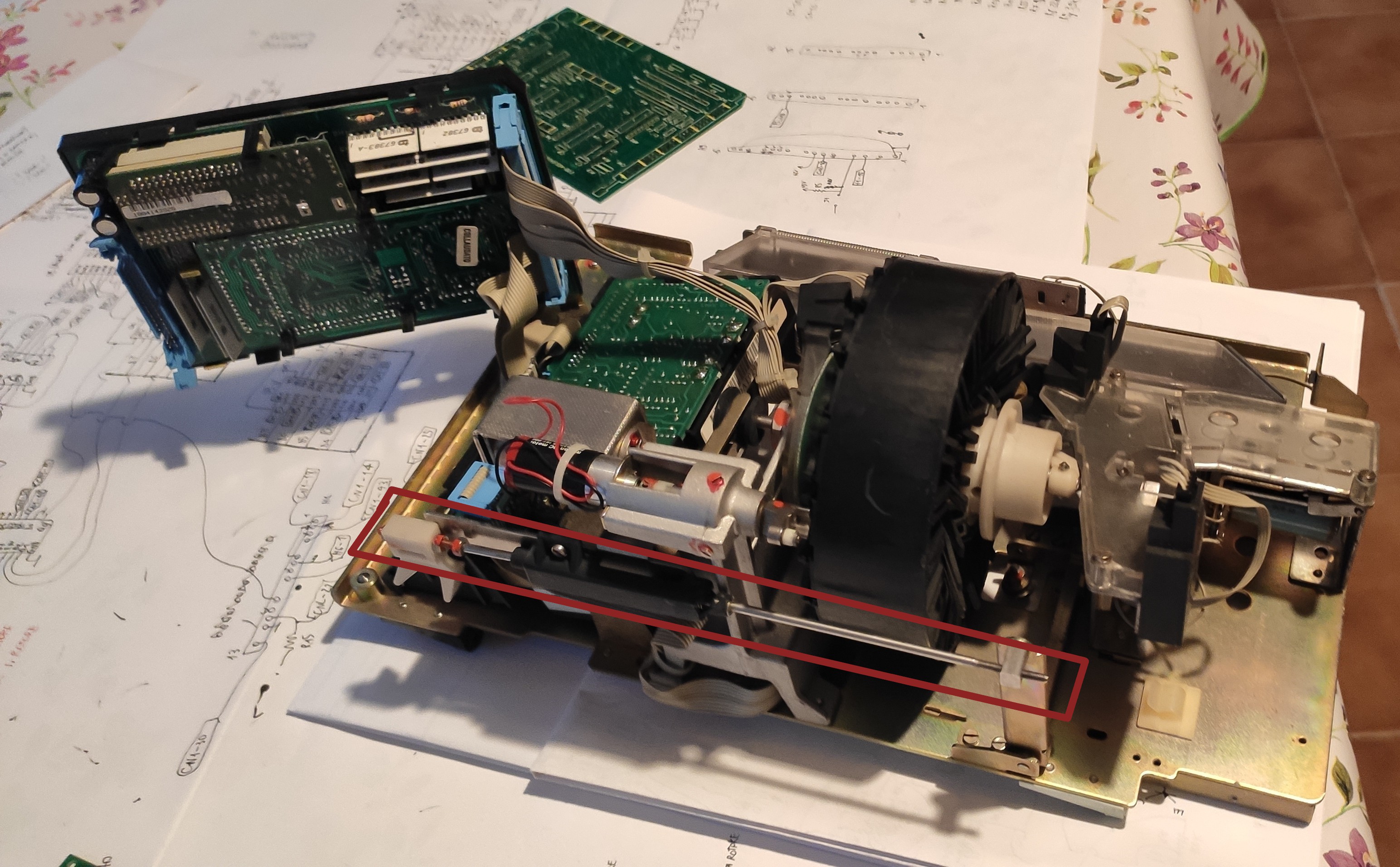
The mechanical section is quite straightforward:
First of all, coins enter from the slot you can see in the top right, roll down and to the side and pass through the coin discriminator module (vertical PCB you can see below the main board), which performs a series of measurements on them; the metal rod you can see circled in brown controls a flap inside the discriminator module, which, when opened, makes the coin completely bypass the discriminator itself and fall straight down to the change tray. The rod is controlled by the "redial" button on the keypad and is used to attempt to clear a jam in the mech (the coin discriminator is the tightest part of the coin path, so if the user inserts anything that is not a coin it should stop there).
After being analyzed, the coin gets to the clear polycarbonate coin channel you can see all the way to the left in the first picture. Here it encounters the first "barrier" (cyan), controlled by a solenoid; if the barrier is open (default) the coin is rejected and goes down to the change tray, otherwise it gets channeled into the coin rotor.
The coin rotor, clearly visible in the middle of the mech, is the heart of the whole thing. It is equipped with a number of "pockets", each one able to store a coin, which are used both to temporarily hold the coin the user inserted and to give out change after the end of the call; it is equipped with two photointerrupters (circled in blue), one on the input side of the pocket and one on the output side, a small DC motor (circled in red) that is used to turn the rotor one pocket at a time, a coin release solenoid (green) and an absolute encoder (magenta), used to track the rotor's position.
After being released from one of the pockets, the coin goes through another clear polycarbonate channel, with one last solenoid-controlled barrier (yellow); when the barrier is open, the coin goes once again to the change tray (this is used to actually give back change to the used after their call has finished), whereas when the barrier is closed the coin gets sent to the phone's safe. Another photointerrupter checks if the coin actually gets in the safe.
All solenoids on the coin's journey have a microswitch used to check their operation.
First power up
After cleaning it up, I tried to power the phone to check how much of it still works. After scratching my head for a bit and realizing that you do need a charged lead-acid battery to be connected for the thing to power up, I had the first signs of life: a blinking "out of service" LED, the card reader turning its motor for a couple of seconds, and nothing more.
After a lot of more headscratching, I figured out my LCD had a dodgy zebra strip; with some pressure on the display frame, I finally had some output. I put the phone in test mode (switches under the display: left one OFF, right one ON) and was finally greeted with a firmware version string and a test menu.
Good news: it passes all checks apart from the ext RAM test (which is expected seeing that the coin cell on there is dead) and the full mech test (broken microswitch mount for one of the solenoids).
Bad news: as expected, the thing can't communicate with the phone company, so it's throwing a whole laundry list of errors at me. I do have a partial error code list, BUT it's for a newer FW version, so it's not that useful. Still, it was cool to see the rotor finally spin under the MCU's control (there's a video of it on my twitter if you're interested)
What now?
Seeing the phone work was a small victory, but there's still a lot of work to do. However:
- All boards (except for the coin discriminator, which should be an off the shelf module) have been traced in one form or the other; I just need to clean them up and redraw them on KiCAD. I managed to complete the line interface board schematics, which you can find here on github (you can also find some interesting stuff, such as part of the phone's manual, there)
- All the pesky ceramic modules have been traced, except for the card reader head amplifier. You can find the schematics in the same github repo.
- About the custom chips: thanks to the fabulous work by Boris Marmontel (@TICS_game on Twitter), we now have hi-res die shots of both of the custom chips. You can find them on his site here. We're currently working on reverse engineering the V7308-T1-N4 chip from the O.V. boards.
- I've begun getting some logic analyzer traces on the phone initializing itself, to be able to follow the firmware dumps. Of course some idiot (see: me) made a mistake on the adapters for the logic analyzer probes, so my traces are corrupted. I'll have to redo them.
- There's work to be done on the card reader. The one that came with the phone is filthy and has some broken parts; I have my old spare one, but it's an older revision and there's some differences. Also, the newer one has an add-on board with yet another microcontroller, an 8051, which I need to dump.
Miscellaneous:
With the help of the lockpicking101 forum users, I managed to decode the key that is used on all Rotor 2/O.V. phones. Here's a pic:

It's an Abloy Profile key and the bitting is 41312 (where 0=0° and 5=90°, read from the tip skipping the 0° section that is common to all Profile keys)
Also, thanks to good old eBay, I got ahold of some more pictures from the original documentation for these phones; I'm missing quite a lot (it got sold to somebody else) but there's a detail that is very useful for our work: the Rotor 4F phones uses what is described as "telegraphic" communications. Basically this means that the data is exchanged by flipping the comms-dedicated phone line polarity (done by the phone company equipment) and opening/closing the line (done on the phone side) with specific timings.
About the mistery of 2F phones with card readers: I've found a section in the documentation that talks about a newer revision 2F board that is equipped with the card reader interface; I've never seen it, but apparently it exists. No idea of how comms worked on those, since all evidence points to the 2F phones not having comms capability.
About the OV boards: to me, they look like they're meant as newer-revision/replacement boards to use with two-wire phones to give them full comms/card reader capabilities. However, I tried putting an OV line interface + CPU board in my 4F and it doesn't work; if anything, it looks like it killed the controller on my LCD board. Probably there's a special variant of the "main" board (the one that lives above the mechanical section) to use with these. So, if anyone reading this has an OV or a TPDC/"Rotor 3" (basically a repackaged OV with no coin mech and a different LCD), please get in touch with me.
Discussions
Become a Hackaday.io Member
Create an account to leave a comment. Already have an account? Log In.