Close
0%
0%

Relay Economizer

JLCPCB Sponsored Relay Economizer PCB Project with Penn Electric Racing

Similar projects worth following
693 views
0 followers
This board (sponsored by JLCPCB) will allow us to have a higher power efficiency by creating a PWM signal to control our relay coils.

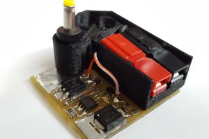
The Relay Economizer is a board that will be used to prevent power dissipation when the car is not active. It uses a DRV110 device to regulate the current through the relay terminals with a well-controlled waveform to reduce power dissipation. When the Relay Economizer is closed, there will be less current flowing through. To maximize battery performance, preventing unnecessary power dissipation is necessary.

Key components:

DRV110: The DRV110 device is a PWM current controller for solenoids. It is designed to regulate the current with a well-controlled waveform to reduce power dissipation. When the solenoid current is high, it will close the relay. After closing, it will keep the constant flow of the current to ensure correct operation of the connected relay and reduce power dissipation. 


Features:

  • Internal Zener Diode on Supply Pin for High-Voltage Operation
    • 120- and 230-V AC Supply Through Rectifier and RS Resistor
    • 24-V, 48-V, and Higher DC Supply Through RS Resistor
  • Drives an External MOSFET With PWM to Control Solenoid Current
    • External Sense Resistor for Regulating Solenoid Current
  • Fast Ramp-Up of Solenoid Current to Ensure Activation
  • Solenoid Current is Reduced in Hold Mode for Lower Power and Thermal Dissipation
  • Ramp Peak Current, Keep Time at Peak Current, Hold Current, and PWM Clock Frequency Can Be Set Externally.
  • Protection
    • Thermal Shutdown
    • Undervoltage Lockout (UVLO)
  • Operating Temperature Range: –40ºC to +125ºC

See more @https://www.ti.com/product/DRV110#product-details##params

Adobe Portable Document Format - 314.46 kB - 10/15/2022 at 21:38

Preview
Download

Adobe Portable Document Format - 324.07 kB - 10/09/2021 at 15:37

Preview
Download

BOM_Relay_Economiser.csv

BOM for Relay Economiser

Comma-Separated Values - 886.00 bytes - 10/09/2021 at 15:37

Download

  • 2 × 2 contacts Male header Connector Male Header 1X2 vertical 2contacts pitch Tin finish polarized, notched
  • 1 × TNPW060352K3BEEA Resistors (Fixed) / Thick Film Surface Mount
  • 1 × FDB33N25TM Discrete Semiconductors / Power Transistors and MOSFETs
  • 2 × C1608X5R1H105K080AB Capacitors / Ceramic
  • 1 × 1M5 5% 0805(2012) 1M5 0.125W 5% 0805 (2012 Metric) SMD

View all 10 components

  • 1
    Ordering the PCBs

    Now, with our PCB design in hand, it's time to order the PCBs and Assembly. For this step, head to JLCPCB.com, and click on QUOTE NOW.

    JLCPCB has sponsored our project. JLCPCB (ShenzhenJLC Electronics Co., Ltd.), is the world's largest PCB prototype company and the leading high-tech manufacturer specializing in quick PCB prototypes and small volume PCB production. You can order PCB and SMT Assembly starting at just $2 for 5 PCBs. You can read more about them on our website here: https://www.pennelectricracing.com/s/JLCPCB-Sponsorship-Document.docx

  • 2
    Add Your Gerber File

    After exporting your gerber and drill files from Altium (see Files section for instructions), compress them and upload your zip file to JLC's website.

  • 3
    Confirm Options

    Here, you can see we successfully uploaded our zip file. We are then able to review our board using the Gerber Viewer function to ensure that both the Top and Bottom layers look good.

View all 4 instructions

Enjoy this project?

Share

Discussions

Similar Projects

Does this project spark your interest?

Become a member to follow this project and never miss any updates