Close
0%
0%

450V HV Indicator

JLCPCB Sponsored LED indicator PCB Project with Penn Electric Racing

Similar projects worth following
0 followers
This board (sponsored by JLCPCB) steps down our 450V battery pack voltage down to 12V, which then powers an LED to indicate that High Voltage has left our battery pack.

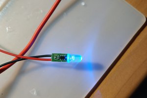
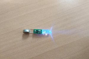
The HV Indicator board steps down 450V to 12V, using the LTC8316, an isolated Flyback converter.The indicator light is an LED on the accumulator that turns on whenever HV has left the accumulator, even when the accumulator is removed from the car. This is done for safety purposes, so people can tell when HV has left the accumulator. By FSAE competition rules, it must be directly powered by HV which is why a buck converter is directly tied to the 450V signal. The zener diode will not pass voltage below 39V, to make sure that when 39V+14V (minimum operating voltage for the buck) = 53V, the LED indicator light will turn on.

Key components:

  • LTC8316
  • 11328-T078

LTC8316

Wide Input Voltage Range: 16V to 560V (600V max)

  • No Opto-Isolator Required for Regulation
  • Quasi-Resonant Boundary Mode Operation
  • Constant-Current and Constant-Voltage Regulation
  • Low-Ripple Light Load Burst Mode® Operation
  • Low Quiescent Current: 75μA
  • Programmable Current Limit and Soft-Start
  • High-Voltage Spacing

See more @https://www.analog.com/media/en/technical-documentation/data-sheets/lt8316.pdf

11328-T078: A transformer for HV and LV isolation on the board for safety and rules. The transformer splits up the majority of the HV sensing (done through the LT8316) from the diode and filtering around it, which is the portion of the board that is LV.

Features/Specifications:

  • Environmental RoHS compliant without exemption, REACH compliance
  • Operating temprature range: -40°C to 125°C (ambient + Temp rise)
  • Storage temperature range: -40°C to 125°C

sheet - 12.48 kB - 10/15/2022 at 22:24

Download

Portable Network Graphics (PNG) - 327.46 kB - 10/15/2022 at 22:24

Preview
Download

Adobe Portable Document Format - 314.46 kB - 10/15/2022 at 21:45

Preview
Download

  • 1
    Ordering the PCBs

    Now, with our PCB design in hand, it's time to order the PCBs and Assembly. For this step, head to JLCPCB.com, and click on QUOTE NOW.

    JLCPCB has sponsored our project. JLCPCB (ShenzhenJLC Electronics Co., Ltd.), is the world's largest PCB prototype company and the leading high-tech manufacturer specializing in quick PCB prototypes and small volume PCB production. You can order PCB and SMT Assembly starting at just $2 for 5 PCBs. You can read more about them on our website here: https://www.pennelectricracing.com/s/JLCPCB-Sponsorship-Document.docx

  • 2
    Add Your Gerber File

    After exporting your gerber and drill files from Altium (see Files section for instructions), compress them and upload your zip file to JLC's website.

  • 3
    Confirm Options

    Here, you can see we successfully uploaded our zip file. We are then able to review our board using the Gerber Viewer function to ensure that both the Top and Bottom layers look good.

View all 4 instructions

Enjoy this project?

Share

Discussions

Similar Projects

Does this project spark your interest?

Become a member to follow this project and never miss any updates