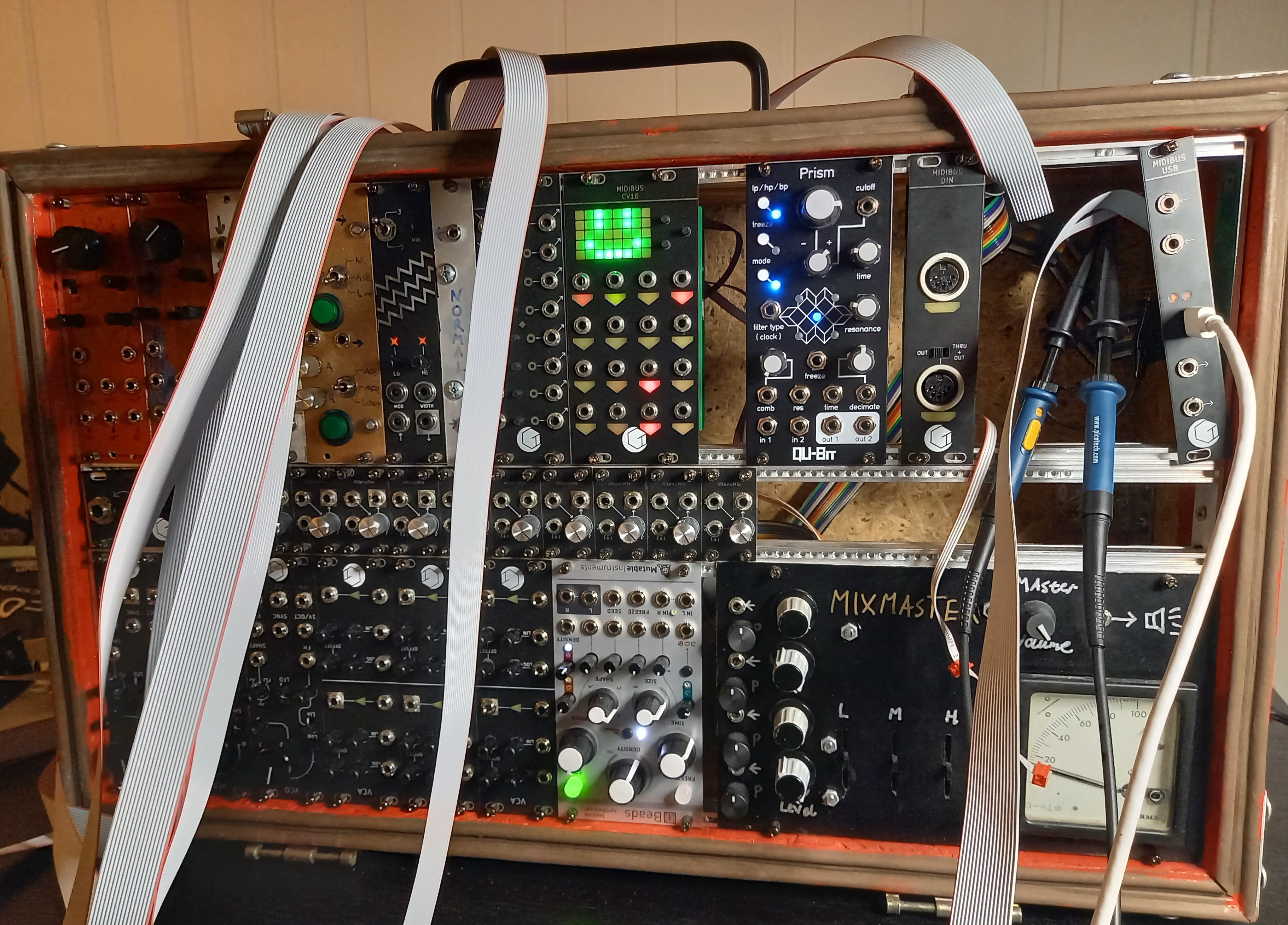
 David
DavidLong time no write, life got busy for a while. Anyway, I've been taking a closer look at the CAN bus used in this system. I have earlier guesstimated the performance of the bus, and I wanted to verify that it's going to work well. The tests I have performed so far look promising from what I can tell.
First I tested the bus with a 10m cable, a cable of that length would cover the vast majority of modular setups. A 16-pin cable was used because it was almost the same cost as a 4-pin cable, and I can use this one to make power cables later. My biggest concern with this test was reflections of signals on the bus, but to my surprise, I could not find any. The cable has a propagation time of 4.9ns/m which means the signal can make 10 roundtrips during a single transferred bit, this gives it a lot of time to settle.
Initial measurement:
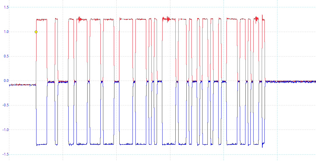
The termination resistance was initially wrong due to a (mis?)calculation of the cable's impedance. It didn't look like it caused any issues, but 240 ohm is outside the ISO spec. Reducing the termination to 120 ohm reduced the signal amplitudes to +-1V which is nominal for CAN.
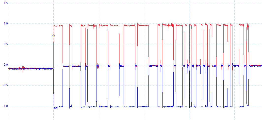
120 ohm measurement:
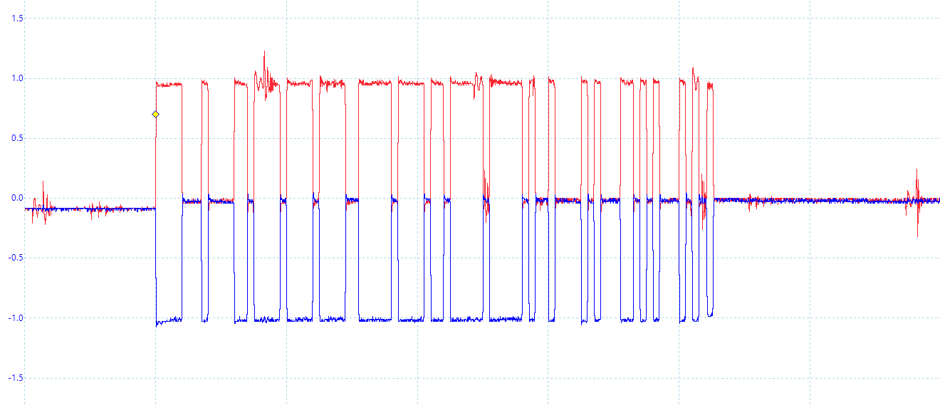
The measurements show some differential noise, which moved to the other probe when the ground clip was switched. So that may be ground bounce from some digital circuit, or possibly from the USB connection. This would probably not be there if the oscilloscope wasn't attached.
Differential noise:
Far-field emission will likely not be an issue, a 75m-100m long bus cable would be needed to form a half-wave dipole. It could still form a short dipole though, but as far as I understand it would only be an issue if one end of the bus has a high impedance. This could happen if someone forgets to connect the termination resistance, but that would be a user error, not an issue with the bus.
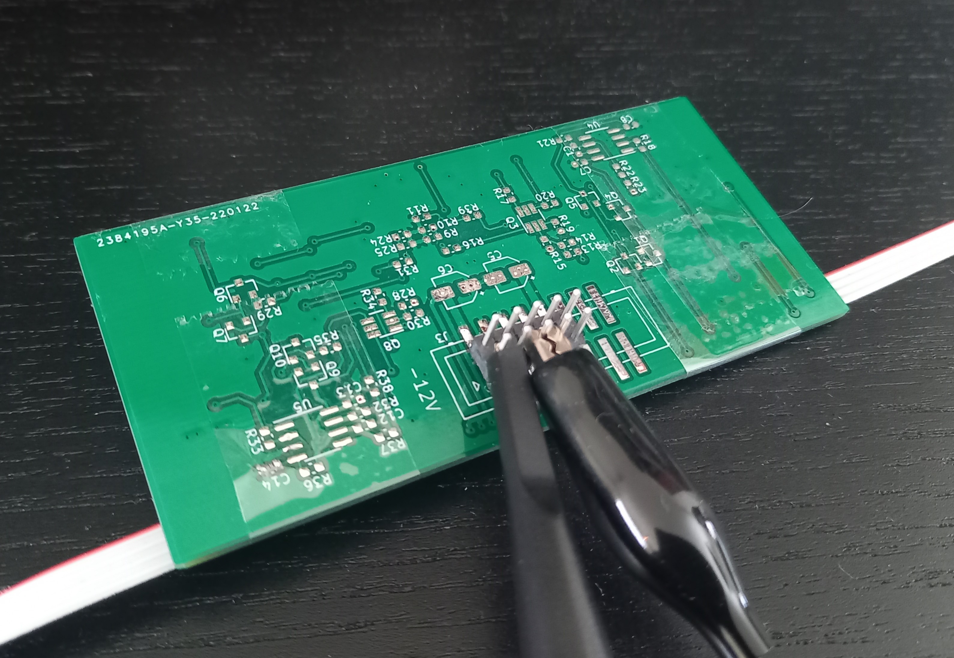
The next test was measuring the near-field emissions since the cable will be in close proximity to many other modules. I was considering getting a near-field probe for this, but I wouldn't know how to interpret those results. I imagine one of the worse situations that could occur is the bus laying in parallel with a long high-impedance trace on a module. So I grabbed one of the PCBs I had from old prototypes, found a long trace (~66mm), soldered a 1 Mohm resistance to ground, and taped the bus cable along this trace.
The test setup:
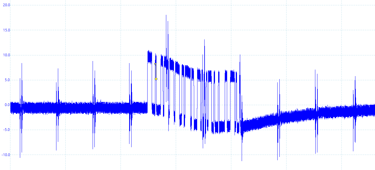
The signals measured on this trace had an amplitude of 10mV, which would be 0.1% of a typical analog signal in eurorack. I would say that's pretty good for a worse-case scenario.
Radiated signal:
Moving on to the connectors, there is one important property I've overlooked: the number of mating cycles. The connectors I have are only rated for 25 mating cycles, and the springy part is on the PCB. The bus connection is not supposed to be disconnected and reconnected often, but it would still suck having to de-solder the connector if it wears out. It seems like the manufacturers are giving a low estimate though, I tried 100 cycles on a connector and don't notice a difference in its strength. I haven't found a great alternative for 4-pin IDC connectors, so I will keep using these.
I also want to utilize more of the built-in features of the CAN controllers. These controllers have hardware filtering of message IDs, it would be a shame not using that at all. But the message ID is also used for arbitration so some of it must be random to prevent message collisions. Message type and midi group would be good candidates for filtering, but using both in the ID would let the bus support only 8 modules. I will probably put the message type in the ID field and leave the rest random. This will let a module filter out message types it doesn't use (like sysex), so the MCU won't be interrupted when they are sent over the bus.
One of the big features of CAN FD is the flexible data rate, allowing the payload to be sent at a higher data rate to increase data bandwidth. This increased data rate must be configured in every node before it can be used, otherwise, the nodes will misread the data. So, I have specified time segments for 4 Mbps. The frame header will still be 1 Mbps, so the gains are greater for bigger payloads.
Speaking of bigger payloads, we could send more than one MIDI packet in the same CAN frame. This wouldn't make sense for most message types as we want low latency. But data/sysex messages can consist of several MIDI packets, which would make sense to send together. This takes up more memory per message in the buffers, but a module can filter out these message types to save memory if they're not used.
Finally, I have also updated the driver for the CAN controller to make it easier to port for other MCUs. Have only implemented it in the USB module so far.
With all of that out of the way, it may actually be time to start revising the PCBs.
Discussions
Become a Hackaday.io Member
Create an account to leave a comment. Already have an account? Log In.