Next up is the multiplexer module's revision, there are no drastic changes on this one either. Like the DIN module, this gets an SMD USB connector, 5V rail protection, a latching bus connector, and bootloader buttons.
I also added reverse voltage protection on the +-12V rails. It shouldn't be necessary since I'm using shrouded power connectors, but it's an open-source project so people may change the components when re-creating it.
Something I discovered with this module was that unconnected inputs caused crossover noise, so signals would appear on other inputs. I fixed this by soldering the connector's tip switch to ground so the wires are grounded when no jack is present. This has now been added to the PCB.
I added an external EEPROM which means the routings and settings finally can be saved between power cycles. Not needing to re-configure the module every time will make it much more convenient to use.
This module was using every available pin on the MCU (even the SWDIO pin was used for a LED), and I needed some pins for the buttons and EEPROM. So I needed to add shift-registers to control the MUX selection. This reduced the number of pins needed to control the MUXes from 24 to 3.

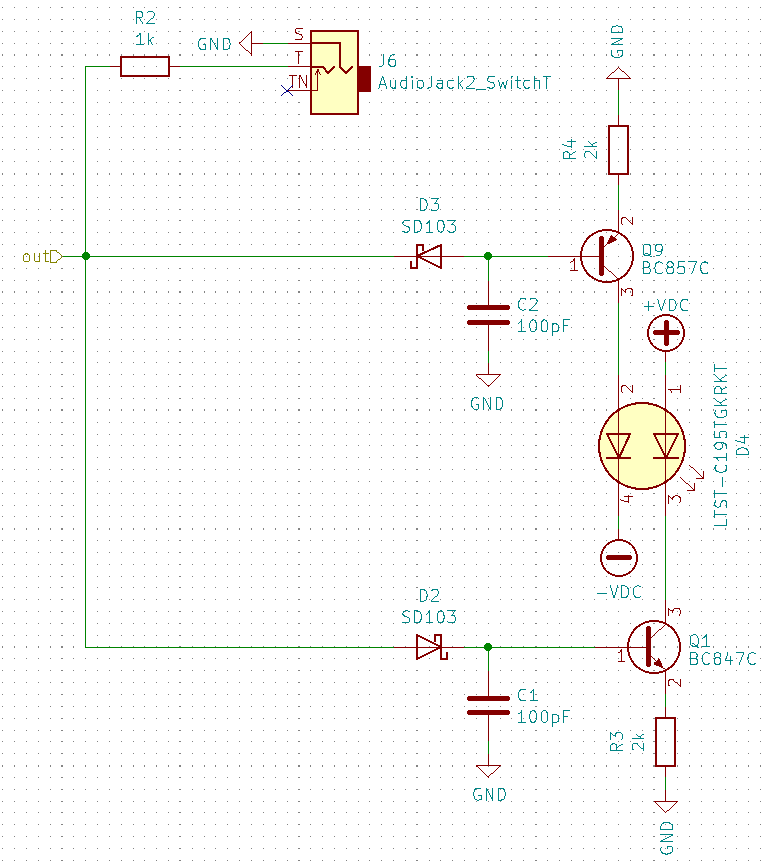
The bi-color LEDs were changed from a 2-pin to a 4-pin version so both colors can shine simultaneously. This should have a better effect for audio-rate signals. The LEDs should now be green for positive signals, red for negative, and yellow for audio rate (becoming brighter with higher frequencies). This is implemented with a peak-detector circuit for each LED. The opamp can't drive high capacitive loads though, as anything over 100pF may reduce the slew rate or cause instability. Therefore the capacitor is discharged via a transistor to amplify the current. This means the discharge time depends on the gain of the transistor. Using transistors also lowers the voltage needed to drive the LEDs, so the dead zone where neither LED shines will be smaller. I could not find a THT version of these LEDs, so it will use an SMD version with a light-pipe.
 David
David
Discussions
Become a Hackaday.io Member
Create an account to leave a comment. Already have an account? Log In.