This project was developed in partnership with the company JLCPCB. When performing the reading, you get 5 free units of a printed circuit board for you to assemble your project.
The automatic fish feeder with Arduino is a great idea for anyone who wants to take care of a fish. Through this tool your fish will always be fed.
During certain intervals of time, the system will release food to all the fish in the aquarium. Do you want to understand how this system works and make your own?
If yes, then come learn all the step-by-step steps to build this project.
The 5 units of this shield were made available for free for you to receive in your home and use in any project with Arduino.
You must follow all these steps below.
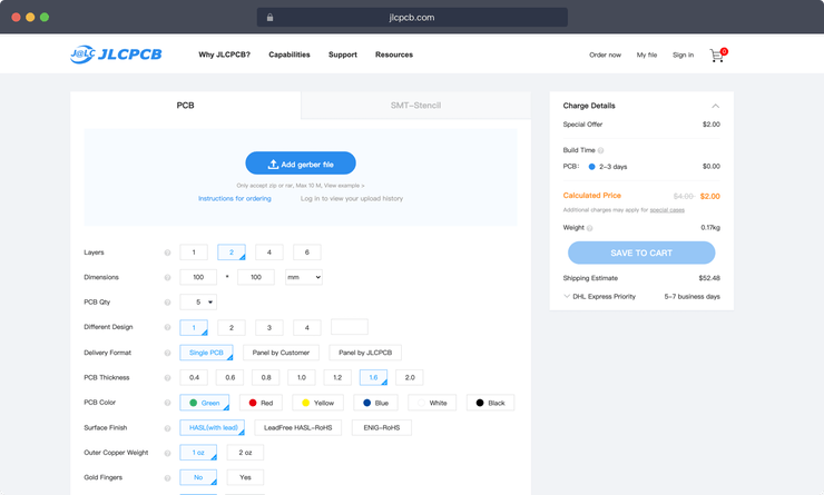
- Enter on the JLCPCB website and make your account.
- Add the control board files to the website
- Add the JLC-REBE discount coupon to the payment section
- Ready, you won 5 free PCB units.
Watch the video below and learn the complete walkthrough.
https://jlcpcb.com/video/homeOrderVideo.mp4

See below for some images of our project and its parts.


Now, let's understand how the project works. Let get started!
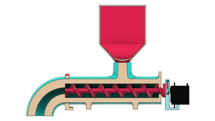
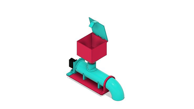
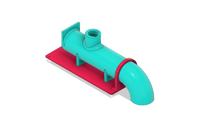
The design of the diy fish feeder with Arduino is shown in section in the figures below.

Next, we will present the pieces that make up its structure.
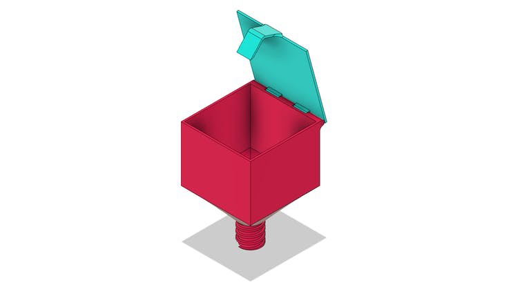
The base of DIY fish feeder with Arduino
The base is a piece created to facilitate the attachment of the feeder frame in any location. The base part is shown in the figure below.

In the structure of this piece, we will fix the transmission tube of the fish feed grains.
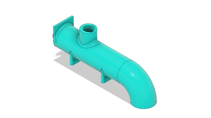
Tube for transporting fish feed grains with Arduino
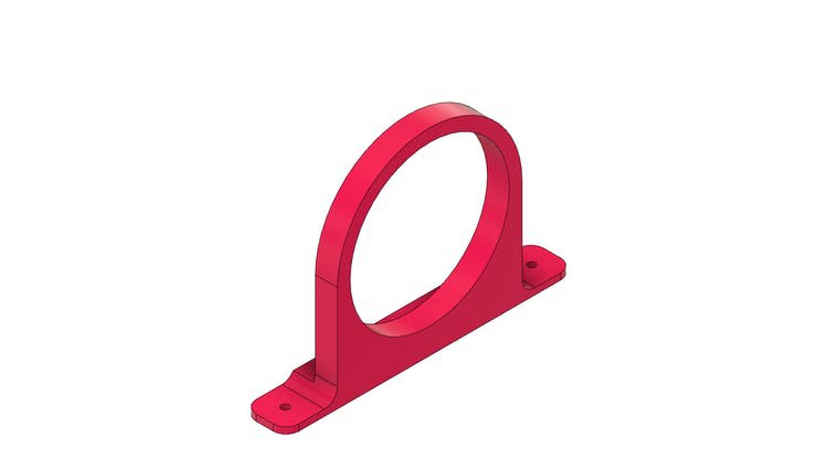
The tube is shown in the figure below. Its structure is mounted on the base piece with the aid of a collar that will be installed with M3 screws.

In the tube body there is a threaded hole. This hole is used for fixing the fish feed tank.
DIY Fish Feeder Feed Reservoir with Arduino
The feed tank has an approximate dimension of 95 x 95 x 126 mm. Its structure will be connected to the transport tube by means of a thread.
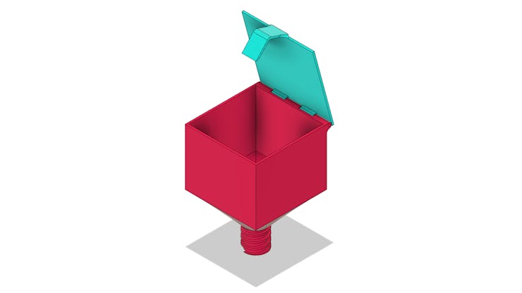
The feed will go down through the hole and will be transported to the exit through an Archimedes screw. Do you know how an Archimedes screw works?
The working mechanism of Archimedes' screw
Archimedes' screw is a very old invention and used by several civilizations to transport water in irrigation systems.
Its structure is presented below.

The video below presents the use of the mechanism by ancient civilizations
The screw was manually moved to transport water from one level to another.
Over the years, the mechanism has been improved and engines are now used to move it. In addition to transporting liquid, the system allows transport of solids.
Watch the video below and observe the transport of solids
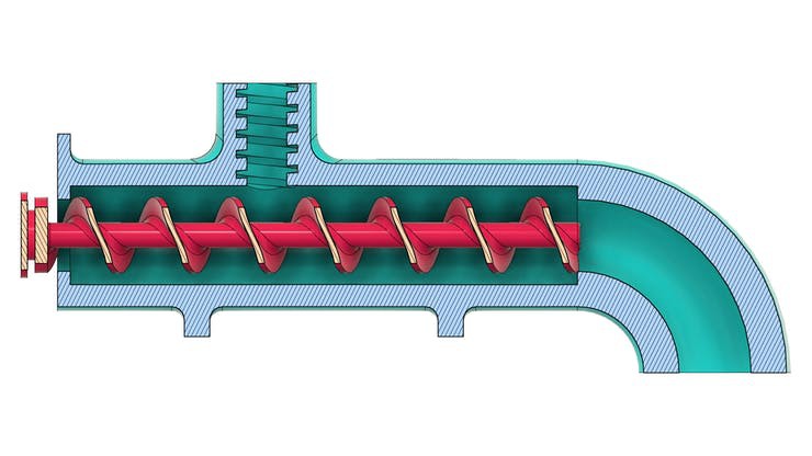
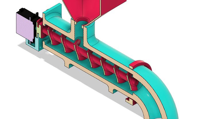
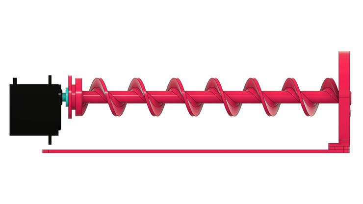
The figure below shows the tube system with the screw installed internally in its structure.
In the sectional view, it is possible to observe the threaded region for food entry and its movement through the tube to the exit location.
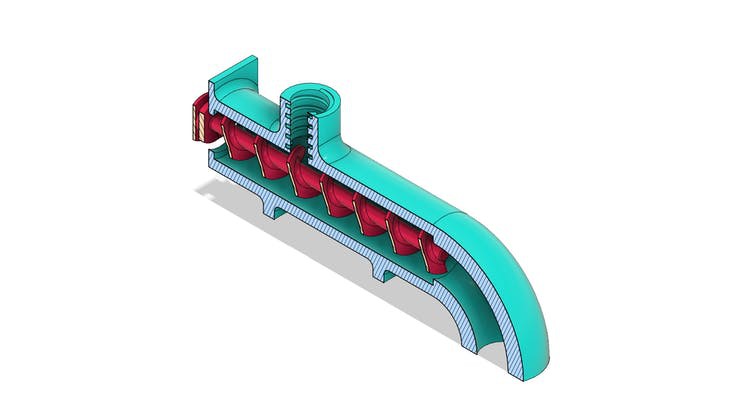

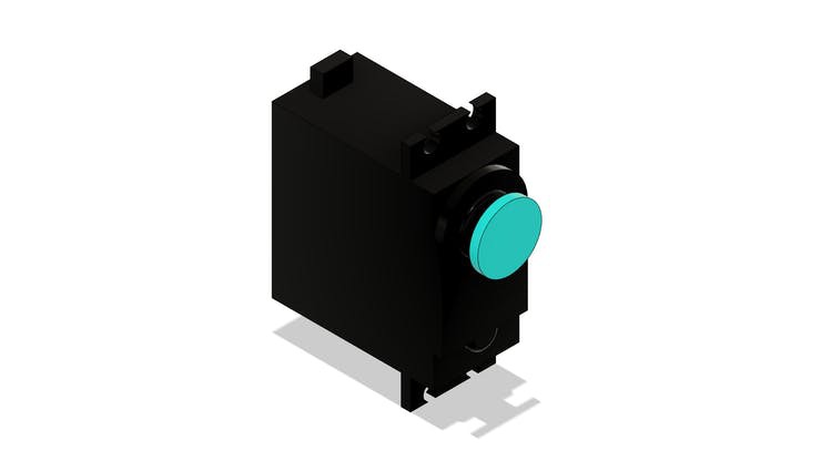
To transmit movement we use a servomotor with continuous rotation coupled to the archimede screw.
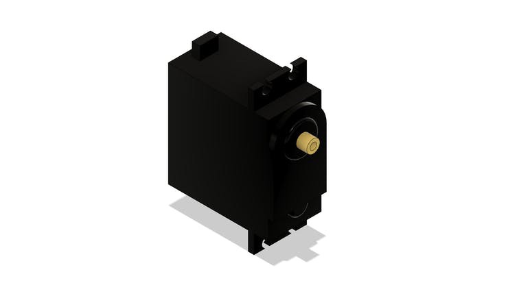
Servo motor with continuous rotation
In this project you can use a direct current motor or a servo motor.
To facilitate the construction of the project, reduce the complexity of the circuit and facilitate programming, a servomotor with continuous rotation was used.
In the figure below we have the MG996 servomotor.

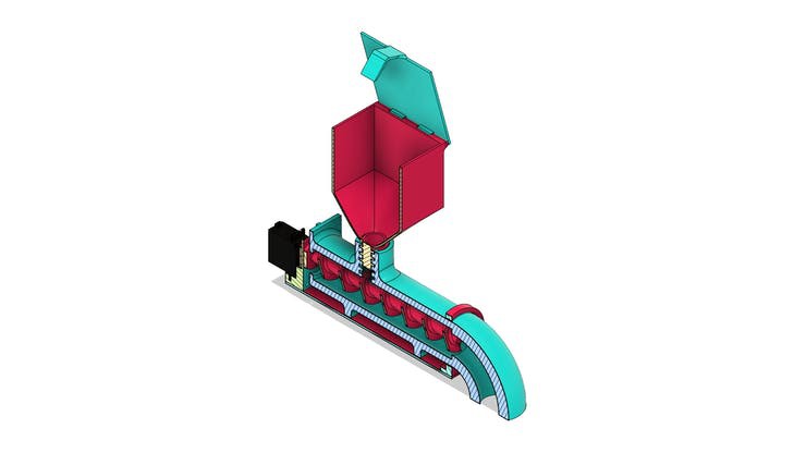
The servomotor will be glued to the screw frame. See the figure below.

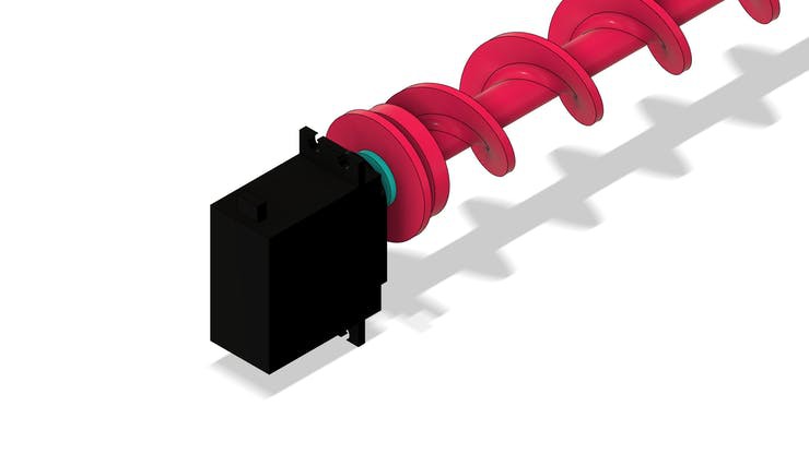
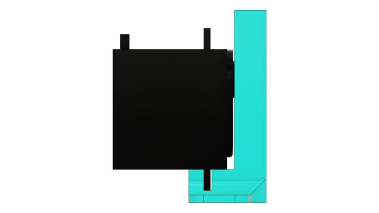
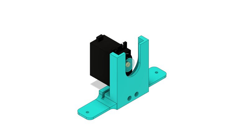
In the structure of the part there are 2 holes to mount it to the base part.
Finally, we have the support collar for installing the feed transport tube.

Did you understand how this project works? Want to have access to files to print to a 3D printer and mount it?
Follow the step by step below to receive the files in your email.
- Enter on the JLCPCB website and make your account.
- Print your screen logged in and send to email: fcodiegomoreira@gmail.com with subject: Send the DIY Fish Feeder with Arduino
- I'll send all files for you
https://jlcpcb.com/video/homeOrderVideo.mp4
Now, let's learn how to create the DIY Fish feeder with Arduino control logic.
Development of programming logic for DIY Fish feeder with Arduino
The logic is to release feed to the fish every 4 hours. This value was selected in the code, but you can change it.
The code to control the DIY Fish feeder with Arduino is presented below.
#include "Servo.h" #include <DS1307.h>#include <Wire.h> //Biblioteca de Comunicacao I2C int DataTime[7];int actual_hour = 0, last_hour = 0;int cont = 0;Servo myservo;void setup() { Wire.begin(); //Inicializacao da Comunicacao I2CDS1307.begin();DS1307.getDate(DataTime);actual_hour = DataTime[4];last_hour = DataTime[4];myservo.attach(9);}void loop() { DS1307.getDate(DataTime); actual_hour = DataTime[4]; if(actual_hour != last_hour) { cont++; last_hour = actual_hour; } if(cont == 2) { myservo.write(180); delay(30000); myservo.write(90); cont = 0; last_hour = actual_hour; } }
Next, we will explain all the programming logic developed.
First, make the declaration of the element libraries used in the project. In this project, a servomotor was used to turn the screw and a DS1307 real-time clock to count the hours.
To carry out the serial communication of the RTC, the wire.h library was used.
#include "Servo.h" #include <DS1307.h>#include <Wire.h> //Biblioteca de Comunicacao I2C do RTC
Make the declaration of all variables and vectors used in the project. The DataTime array is used to store the 7 date and time parameters that the RTC returns.
int DataTime[7];int actual_hour = 0, last_hour = 0;int cont = 0;Servo myservo;
The variables actual_hour and last_hour are variables used so that we can count the hours for releasing the fish feeder.
Finally, create the myservo object to manipulate the servo motor in programming.
The void setup function
The void setup function is used for device initialization and other settings. See the code portion below.
void setup() { Wire.begin(); //Inicializacao da Comunicacao I2CDS1307.begin();DS1307.getDate(DataTime);actual_hour = DataTime[4];last_hour = DataTime[4];myservo.attach(9);}
Initialize serial communication and DS1307 real-time clock module.
Then capture the data from the RTC and store it in the DataTime vector.
DS1307.getDate(DataTime);
Store the time in the current_hour and last_hour variables.
actual_hour = DataTime[4];last_hour = DataTime[4];
Finally, set pin 9 for servomotor control.
Now let's look at the control logic of the void loop function.
Logic in the void loop function
The void loop function presents the complete logic for controlling the DIY Fish feeder with Arduino. See the code portion below.
In each code cycle you must capture the RTC data.
void loop() { DS1307.getDate(DataTime); actual_hour = DataTime[4]; if(actual_hour != last_hour) { cont++; last_hour = actual_hour; } if(cont == 4) { myservo.write(180); delay(30000); cont = 0; last_hour = actual_hour; } }
The hour information is stored in the variable actual_hour.
actual_hour = DataTime[4];
Next, we must check if there has been a change of hours. This process is done by comparing the hours value that was read with the hours value used as a reference (last_hour).
if(actual_hour != last_hour) { cont++; last_hour = actual_hour; }
If the current hour is different from the last hour (last_hour) stored as a reference, the variable cont will be incremented, and the current hour value will be assigned to the variable last_hour.
This value will be used as a reference in a new hour change.
The next condition is used to check if the value of the variable cont is equal to 4.
If this value is true, it means that 4 hours have passed and the DIY fish feeder needs to release feed for the fish.
if(cont == 4) { myservo.write(180); delay(30000); myservo.write(90); cont = 0; last_hour = actual_hour; }
The servo will drive clockwise for a time of 30 seconds and stop. During this interval the food will be moved by the screw and released to the fish.
After that, the variable count will receive the value 0.
cont = 0;
This action is necessary to allow the variable to restart the hour count for the next feed release.
last_hour = actual_hour;
Finally, we have the current hour assignment as a reference to the last_hour variable.
After that, the code flow returns to the beginning of the loop function and repeats the entire process presented in this section.
Do you want to build this project with Arduino quickly and with a less complex circuit? We developed the shield below to facilitate the construction of any project with Arduino UNO.
The shield is shown in the figure below.
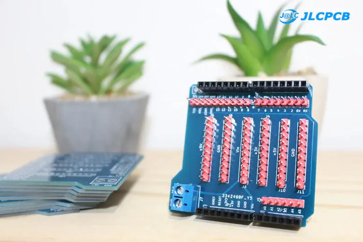
Shield can facilitate the assembly process for your entire project. Find out why!
You can apply it to any project with Arduino UNO.
It is available for download,and you can earn 5 units for free at JLCPCB.Follow the step by step and get the shield right now in your home! It's free!
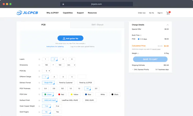
You must follow all these steps below.
- Download the robot control board file
- Enter on this website and make your account.
- Add the control board files to the website
- Add the JLC-REBE discount coupon to the payment section
- Ready, you won 5 free PCB units.
Why use the Shield on Arduino UNO
There are 2 big problems that will arise if you don't use the shield in your project: faulty connections with solders and the absence of power terminals for sensors and other devices.
Let's understand how to solve these 2 problems?
Look, for example, at the project's sensors. We have 4 sensors to detect the elevator's position. See the figure below.

In total, there are 4 GND's and 4 wires for a +5V connection. Unfortunately, we know that Arduino has only 2 GND terminals and 1 connection pin with +5V.
This forces us to solder these wires together and connect to these terminals.
However, in some situations, solder connection problems arose, and the devices did not work correctly in the project. This takes time and keeps you from moving forward.
To prevent this problem and expand the power pins to make it easier to connect all devices, we created the Shield for the Arduino UNO.

You can apply it to any project with Arduino UNO.
It is available for download, and you can earn 5 units for free at JLCPCB.Follow the step by step and get the shield right now in your home! It's free!
You must follow all these steps below.
- Download the robot control board file
- Enter on this website and make your account.
- Add the control board files to the website
- Add the JLC-REBE discount coupon to the payment section
- Ready, you won 5 free PCB units.
Watch the video below and learn the complete walkthrough.
JLCPCB is a company that is concerned with technological development and is here to support you in the production of your projects.
We appreciate the support of JLCPCB for providing all the support for the production of this project.
Enjoy and get 5 free units for any project with the JLC-REBE coupon.