 Dennis
Rubik's-Cube-Solving-Robot
Abstract
Rubik's Cube, a 3-D combination puzzle invented by Ernő Rubik in 1974, is the World’s top-selling puzzle game and best-selling toy. Rubik's Cube is surprisingly complex, there are 43,252,003,274,489,856,000 permutations of a standard 3×3×3 Rubik's Cube. Although humans are impossible to memorize all permutations of a Rubik’s Cube, humans can solve the puzzle as fast as 3.47 seconds. In recent years, a robot developed by MIT students can solve it in 0.38 seconds using an optimal algorithm.
In this project, I developed a Rubik’s Cube-solving robot using a Computer Vision algorithm from scratch. The robot has 4 stepper motors and 4 servo motors as actuators. A camera is included to observe each color arrangement of the face of the Cube in a scrambled state sequentially. The image that the camera observed will be sent through a serial interface to the computer. I implement a solving algorithm that will take the Cube state as input and the sequence of moves that solve the Cube as an output. The sequence of moves is sent to the MCU and is then translated into a series of instructions. The stepper motors and the servo motors then work together to twist the Cube according to the instructions, fully solving the Cube.
Contents
- Abstract
- Motivation
- Introduction
- Materials
- Designs
- Hardware
- Actuators
- Camera
- Electronics
- Programming
- Computer vision
- Thistlethwaite's algorithm
- Firmware
- Challenges and Conclusion
- Reference
- Appendix — Workflow of the Rubik's Cube solving robot
Motivation
In recent years, Computer Vision becomes more popular. Computer Vision has a lot of applications, such as object detection, event detection, video tracking, and color recognition. To familiarize myself in the field, I decide to develop a robot that solves a Rubik’s Cube using Computer Vision.
The goal is to fully solve a Rubik’s cube by twisting it using clamps attached to stepper and Servo motors. We will use a camera to capture each face of the cube. A computer will then be used, using the computer vision algorithm, to process these images and find out the color of the 9 stickers in each face. Once the color states of the cube are determined, the computer can then compute the sequence of moves that fully solve the cube.
Introduction
I design the robot using Fusion 360 and Eagle. This robot consists of 4 stepper and Servo motors, 4 pairs of 3d-printed clamp and frame, a camera, and a PCB board with a microcontroller and 4 stepper motor drivers.

The design of the robot ^
To know the initial state of the Cube, I use a camera to capture the color of the Cube. Since the camera can only capture a single face of the Cube each time, the robot needs to rotate the Cube for the camera to capture all the faces of the cube. After capturing, the camera is going to send those images to the computer through a USB port.
The computer will then detect the position and orientation of each face from all 6 images. By using these information, the computer can find out the position and area of each sticker of the Cube in those images. The computer can now extract the color of each sticker, and determine the color of each sticker using computer vision.
Once the initial state of the Cube is found, the computer solves the Cube using Thistlethwaite's algorithm. The solution, the sequence of moves represented in Rubik's Cube Notation, will then be sent from the computer to the microcontroller. Afterwards, the microcontroller translates these notations into a series of stepper and Servo motors movements that twist the Cube and fully solve the Cube.
Materials
- 4 stepper and Servo motors
- 4 3d-printed clamps attached to the stepper motors
- An Arduino nano and 4 stepper motor drivers
- A DC transformer
- A fill light
Designs
Hardware
Actuators
To physically twist and rotate the cube, I use 4 NEMA 17 stepper motors that use a clamp to clip and twist 4 individual faces of the cube. I have considered using DC motors and brushless motors, but both of them can't know their physical rotated-angle without an encoder, so they can't twist the cube precisely.
I have considered using DC motors and brushless motors, but both of them can't twist the Cube precisely because their physical rotated-angle cannot be determined without an encoder.
Although Servo motors can rotate precisely to an angle, most Servo motors can only rotate from 0 degrees to 180 degrees. Therefore, I decided to use stepper motors because they are continuous(they can rotate in one direction infinitely) and can rotate precisely. Therefore, a stepper motor will perfectly fit our use case.
Stepper motors operate using a coil to attract the permanent magnets that encircle the center axle. By energizing the coils, the axle of the motor can rotate precisely by 1.8 degrees. (Stepper motors take 200 steps to make a complete rotation, so its resolution is 1.8 degree = (360° /200 steps))
Stepper motors move in steps. For example, a stepper motor with 200 steps resolution will rotate 1.8 degrees angle for one step (360° / 200 steps).
Simplified stepper motor rotates 3 steps.
Stepper motor is an Open Loop Control System, we don't know its position upon start-up.
In order to twist the Cube properly, the clamp needs to be aligned vertically with the Cube. Therefore, I design a device that uses a distance sensor to provide feedback for the motor to align the clamp and the cube. The device consists of a disk attached to the axle of the motor and an IR Sensor facing the disk. The cube and clamp are in perfect alignment when the IR Sensor faces the hole directly. Hence, by reading the sensor value, the motor can rotate the clamp until it aligns perfectly with the cube.

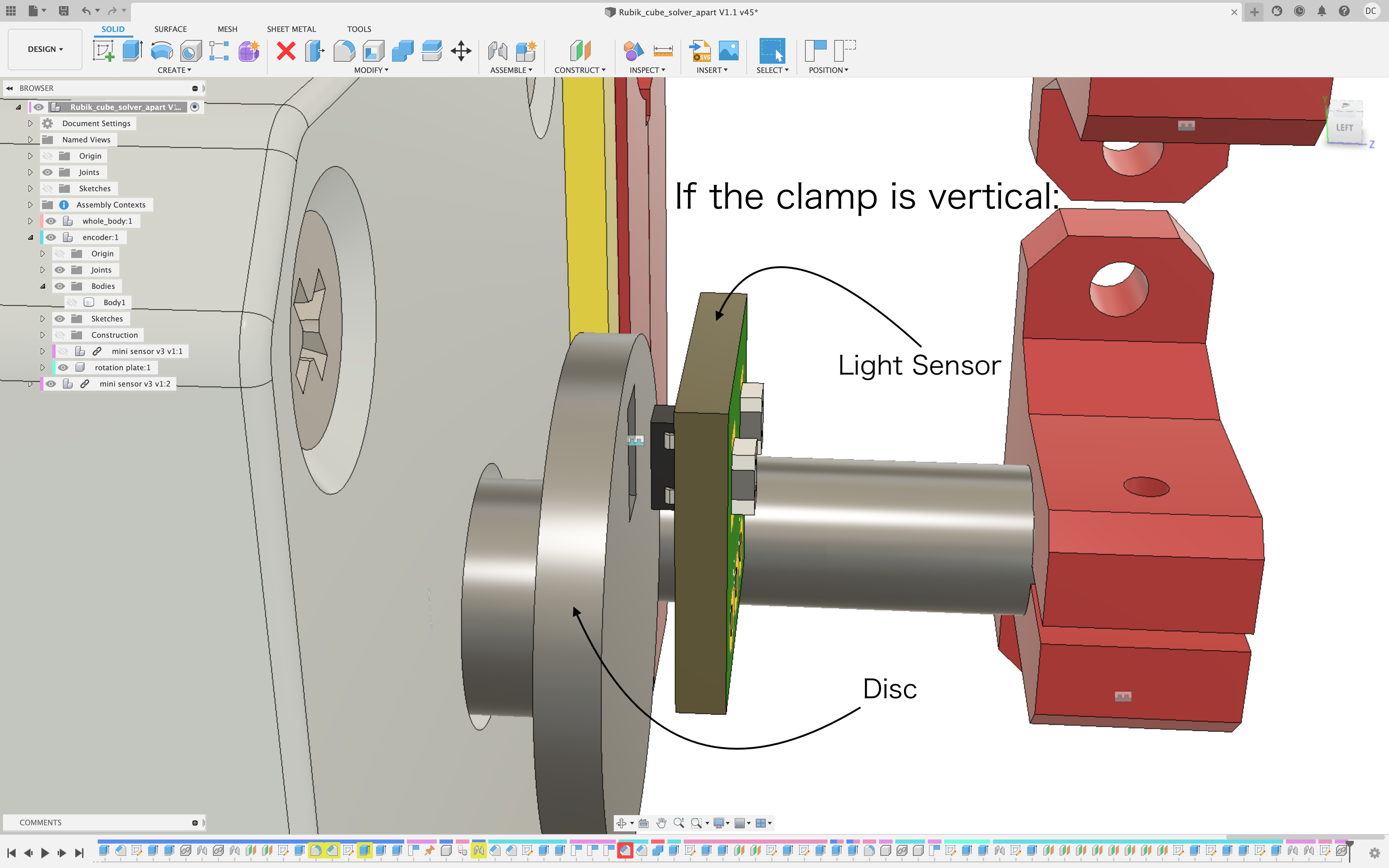

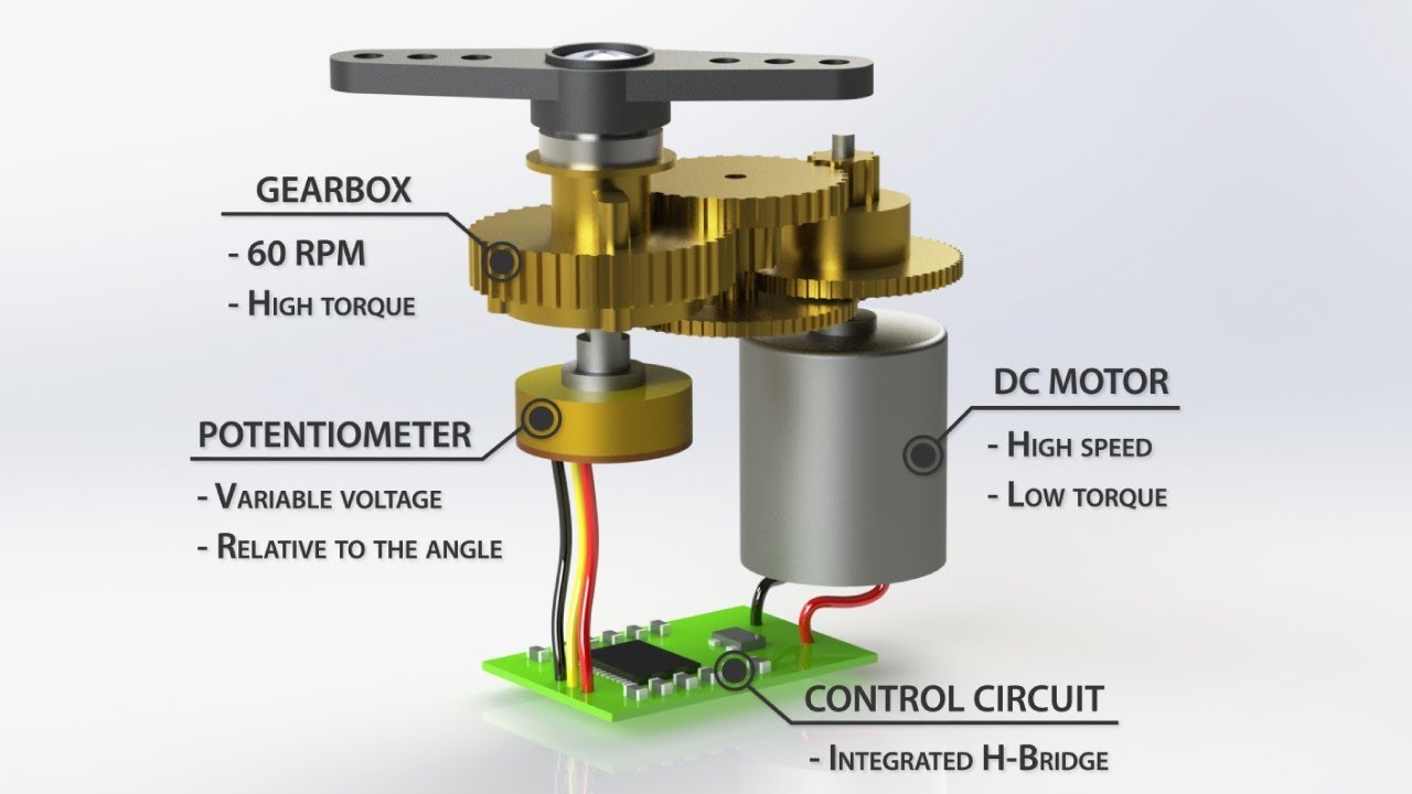
Fig 1
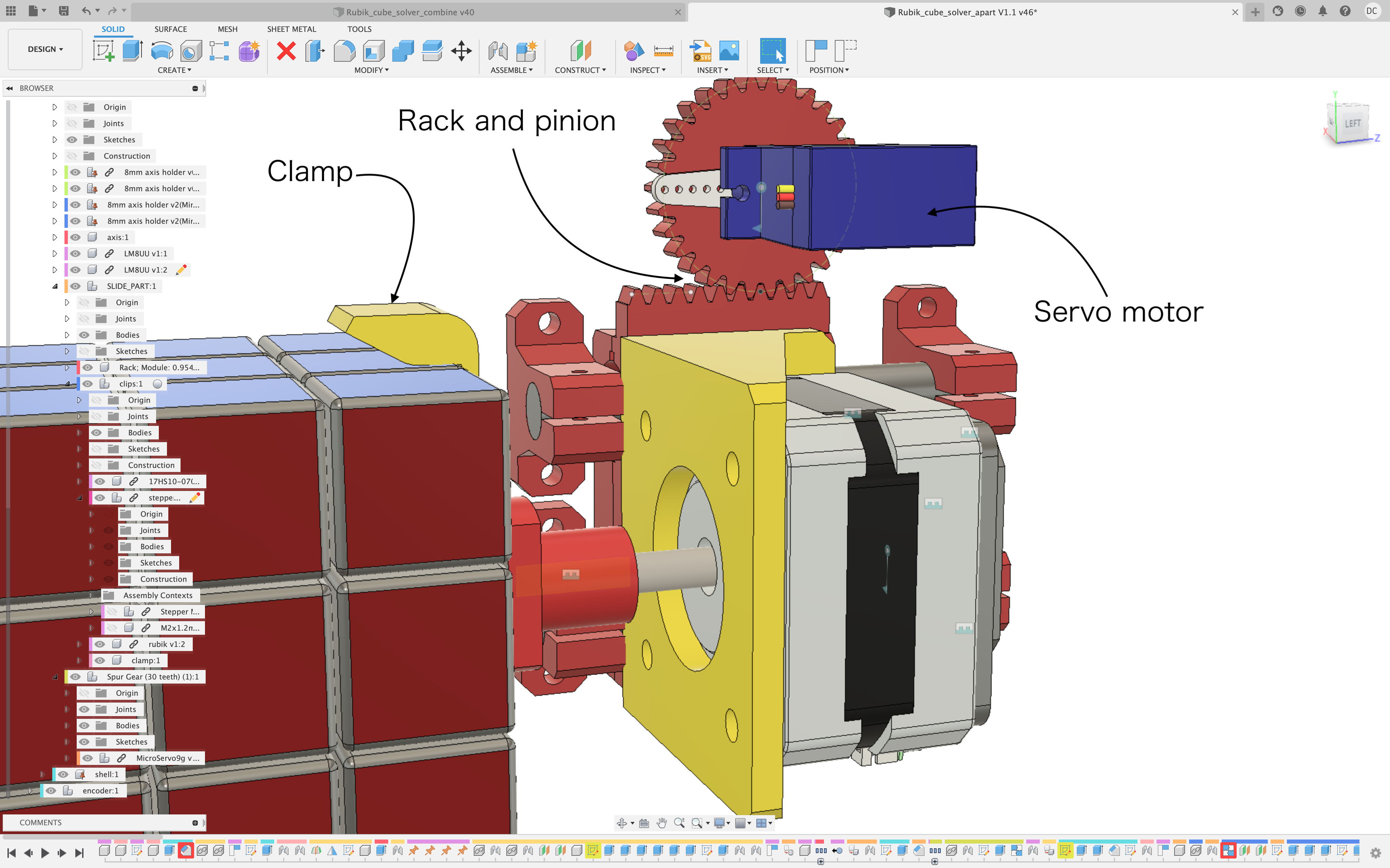
I found a problem when the clamp is twisting the cube. If one of the clamps rotates horizontally, the clamps on its left and right can't twist the cube because the clamp that is horizontal blocks their rotation. Tj is also a Servo motor that is responsible to separate the clamp from the cube so that all clamps can rotate freely. As shown in the image on the left
In contrast to the stepper motor, Servo motor is a Closed Loop control system. When the Servo motor is moving, the position given by the potentiometer as feedback (Fig 1)
is sent to the Servo motor control board to ensure it rotates to the expected position.
I use Rack and pinion mechanics to convert the rotational motion of the Servo motor into linear motion to separate the clamp from the cube.
Camera
To determine the initial state of a Rubik's cube, I use a camera to capture the color of each face of the Rubik's cube. I chose a Logitech Webcam as the camera because it has HD resolution and an autofocus function. Moreover, the camera allows you to adjust the brightness, sharpness, contrast, and saturation of the image. By adjusting these values, the images will become sharper and easier for the computer to distinguish colors.
Trying to distinguish color from the image that the camera sends to the computer, I find that if the ambient light around the cube is unstable, the color recognition program will be extremely inaccurate. To make sure the projected light on the cube is consistent, I added an artificial light source to maintain the brightness of the image. Therefore, I use 4 LED strings to supply light in 4 directions, so the brightness anywhere on the face of the cube is the same.
Electronics
Instead of using a commercial CNC control board that can control stepper motors easily, I am going to design my robot controller PCB that can control 4 stepper motors and 4 Servo motors of my robot because most commercial CNC control boards can't control 2 or more Servo motors. Also, there is a lot of limitations of programming these commercial PCB board, so I decided to make my own control board.
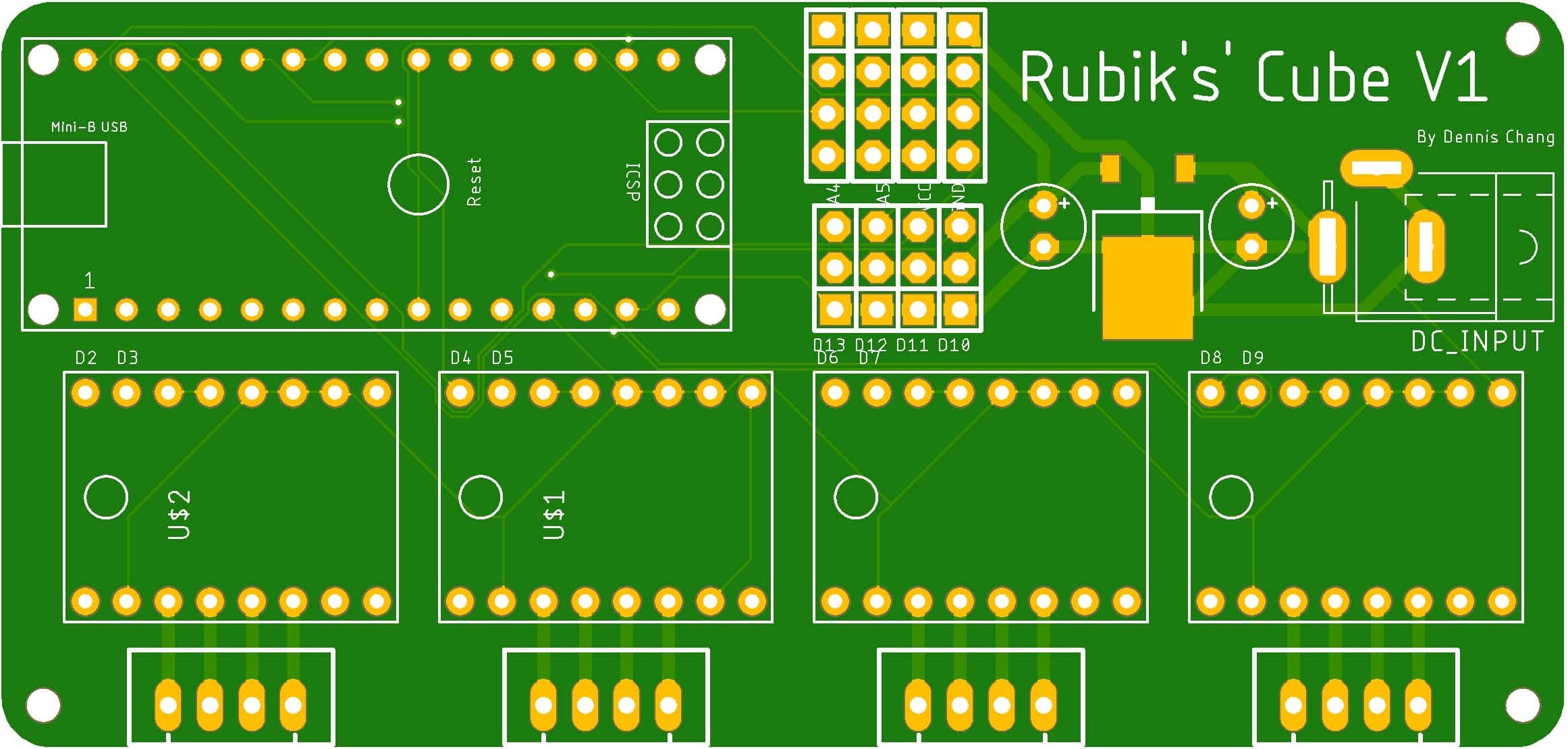
Robot control board
- Microcontroller
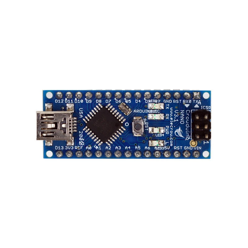
In order to control the whole robot, I decided to use Arduino nano to control the whole system because it is smaller than Arduino UNO and easy to program. Arduino Nano has a built-in Mini USB jack, so it can communicate with the computer through a Serial port with the Mini USB jack.
- Stepper Motor Control
Although stepper motors have a lot of advantages, controlling stepper motors often require sufficient and controlled energy for phases in a precise sequence, so a driver is often needed. Due to this, I plan to use 4 A4988 stepper motor drivers to control all of my stepper motors of the robot.
Each A4988 motor driver required 2 control signal pins (step, direction) and 3 setup signal pins(MS1, MS2, MS3). The step and direction pins are used to control the movement of the stepper motors. The direction pin controls the rotating direction of the motor, and we can control the movement of a step of the motor by sending a pulse to the step pin. The MS1, MS2, MS3 pins are used to control the step of the stepper motor. By changing the input state of these pins to logic low or logic high, you can select one of the five steps resolutions according to the table(Fig 2).
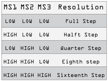
Fig 2
- Servo motors Control
A Servo motor can be controlled by sending a series of pulses through the signal pin. By changing the width of these pulses, we can control the Servo motor rotates to different angles.
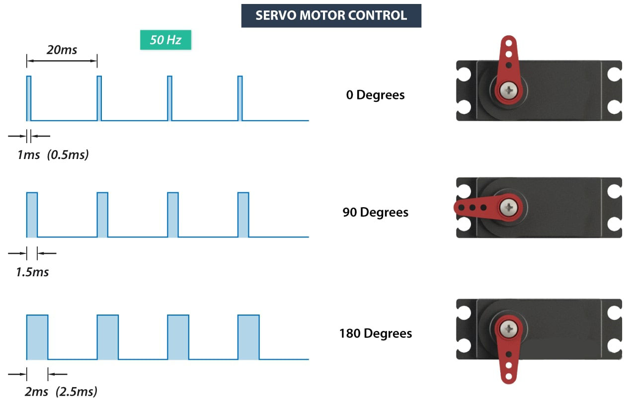
How pulses with different widths control the Servo motor
Programming
Computer visions
In order to determine the color arrangement of each of the images captured by the camera precisely, I implemented a method that can find out the difference between two colors.
A color model is a visualization that depicts the color spectrum as a multidimensional model. There are some commonly used color models in the world. Most modern color models have 3 dimensions (like RGB and HSV), while other models have more dimensions (like CMYK), and I am going to compare these different color models and find out which of them are more reliable in this project.
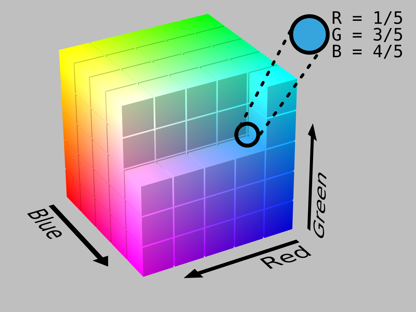
RGB
RGB is a 3-dimensional color model. RGB color model represents a color by mixing three different colors (Red, Green, and Blue). Although RGB color model is commonly used in our daily life, RGB color model is a non-uniform color model, which means the Euclidian distance of two colors represented by the RGB color model does not correspond to the color difference perceived by humans.
Euclidian distance:
$distance=√((R2−R1)^2+(G2−G1)^2+(B2−B1)^2)$
![Untitled]()
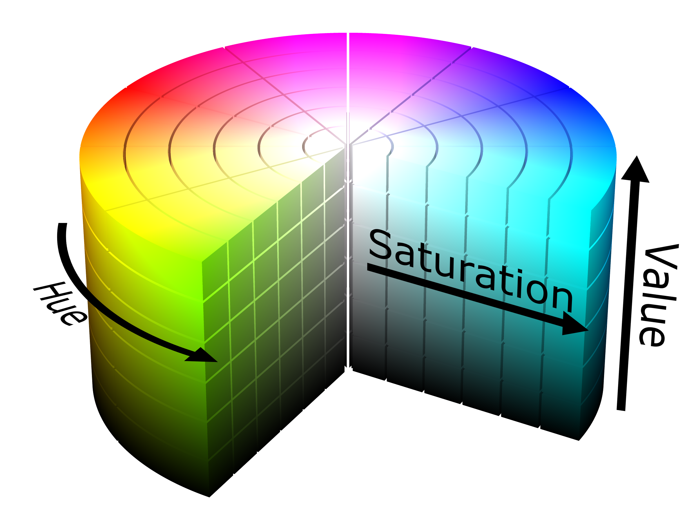
HSV
HSV is a cylindrical color model that remaps the RGB primary colors into dimensions that are easier for humans to understand.
In HSV color model, we can represent a color with 3 variables (Hue, Saturation, Value). Hue controls the angle of the color on the RGB color circle; Saturation controls the amount of color used; Value controls the brightness of the color.
![Untitled]()
HSV (cylindrical color model)
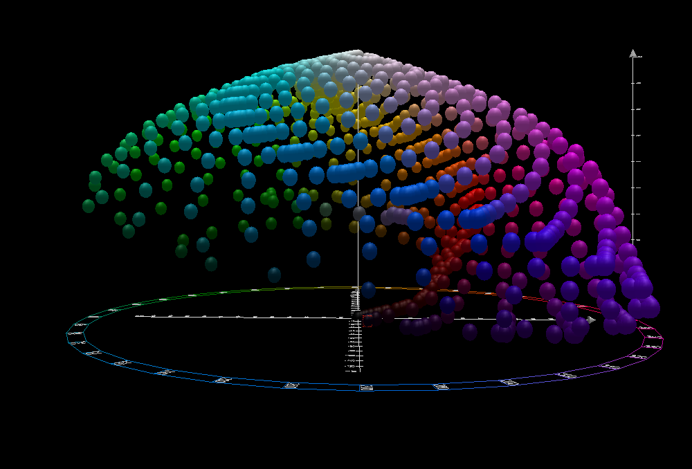
CIELAB
CIELAB color model is three-dimensional, you can represent a color with 3 variables in CIELAB color model while L stands for perceptual lightness, and A and B stand for the four unique colors of human vision: red, green, blue, and yellow. In short, CIELAB is designed to approximate human vision, so it can describe a color more accurate than RGB and HSV color models can.
![Untitled]()
CIELAB color space top view
According to the comparison, I think using CIELAB color model in the Computer Vision method has a lot of advantages, so I plan to use CIELAB color model to represent a color in the Computer Vision method.
When the computer wants to distinguish which color (orange, white, blue, red, yellow, green) of a sticker is, the most important thing is to find out the distance between the sticker pixel color and the reference colors, so the computer can then compare the distance between these reference colors, and distinguish the color. In order to get the color difference between two colors reliably, I use a CIEDE2000 ΔE method instead of the Euclidean distance method because the CIEDE2000 ΔE method is more reliable for human vision.
Given a reference color (L1, a1, b1) and another color (L2, a2, b2), the CIEDE2000 difference of these 2 colors is:

CIEDE2000 ΔE formula
https://en.wikipedia.org/wiki/Color_difference
Where:
https://wikimedia.org/api/rest_v1/media/math/render/svg/2940920f995d52312ede05214ffa3c60f0db9b7f
CIEDE2000 ΔE formula
https://en.wikipedia.org/wiki/Color_difference
Because of the rotation of the cube, the cube position may always shift when scanning the cube, so I have to frequently adjust the cube detect area of the camera manually before scanning it, and I think that adjusting the cube manually is annoying, especially when I'm debugging the program.
Then, I try to implement a cube position tracking program in the solver, so that the solver can adjust the detect area automatically.
The tracking program is actually dum. First of all, the program is going to make the dimmer place of the image more dimmer; the brighter place brighter. The program can then find out the position of the centerpiece of the cube by comparing the pixel of the filtered image. The program can then find out the position of other pieces.
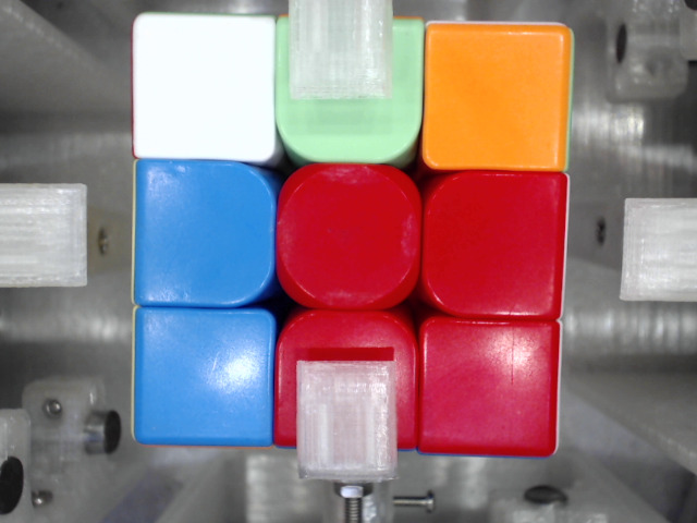
Image before filter

Filtered image
Thistlethwaite's algorithm
After finding the state of the cube, the computer will then solve the cube using Thistlethwaite's algorithm. Thistlethwaite's algorithm is a famous algorithm devised by Morwen B. Thistlethwaite.
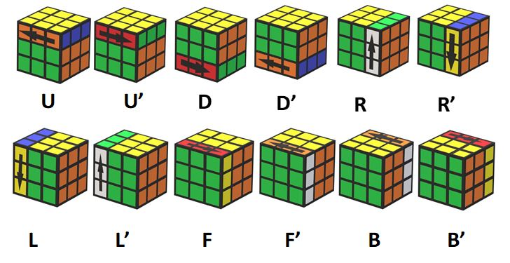
Before I explain how the algorithm works, we first have to know how do people represent a twist of a cube. People usually use a notation called Rubik's Cube Notation to represent a twist of a cube. The twist of a Rubik's Cube is classified into three categories of Notations (clockwise twist, counterclockwise twist, double clockwise twist).
- The notation with only one letter refers to a clockwise face twist in 90 degrees (quarter turn). "F" refers to a clockwise turn of the Front face in 90 degrees.
- The notation with one letter followed by an apostrophe (') refers to a counterclockwise face twist in 90 degrees (quarter turn). "D'" refers to a counterclockwise turn of the Down face in 90 degrees.
- The notation with one letter followed by the number 2 refers to a clockwise face twist in 180 degrees (double turn). "U2" refers to a clockwise turn of the Up face in 180 degrees.
Thistlethwaite algorithm solves a cube by twisting the cube by a certain set of moves. When the cube reaches a specific state, the cube will "move" from one "group" to another. As the cube reaches another "group", the set of moves of the cube will change and the cube will be easier to solve computationally.
The groups are:
- Group 0:
https://wikimedia.org/api/rest_v1/media/math/render/svg/2dbdffdebca6e844bdf3c7548a8033992ef6ac79
Required Cube state: This group contains all possible states of the Rubik's Cube.
- Group 1:
https://wikimedia.org/api/rest_v1/media/math/render/svg/116b5e3559d97ddaa688362537461712c1435f10
Required Cube state: All 12 edge pieces are correctly oriented.
After reaching Group 1, The cube can then be solved without using U and D turns.
- Group 2:
https://wikimedia.org/api/rest_v1/media/math/render/svg/ab29e5a1ef0d23014458f9603f6c108b7aec73a6
Required Cube state: All corner pieces are correctly oriented. Also, four of the edge pieces are moved to the correct slice: the front-up, front-down, back-up, and back-down edge pieces are placed in the M slice.
After reaching Group 2, The cube can then be solved without using F, B, U, and D moves.
- Group 3:
https://wikimedia.org/api/rest_v1/media/math/render/svg/b9990ca7e1121afb33509d738d77f1d0c455be62
Required Cube state: All corner pieces are moved to the correct orbit. (A corner is in the correct orbit if it can be moved to its home position with only 180-degree twists.) Also, each edge piece is moved to its home slice.
At that point, the cube can be solved with only 180 degrees turn.
- Group 4:
https://wikimedia.org/api/rest_v1/media/math/render/svg/27929bbe730561ca9eb1540e72756b5674436bb5
The final group requires only one state, which is a solved cube.
Firmware
In this project, I use Arduino nano board as my microcontroller to control the stepper motors and servo motors. I implement an Arduino stepper motor driver library in the Arduino board to control the movement of the Stepper motors. For the Servo motors, I use an Arduino built-in Servo library to control them.
There is a lot of ways to communicate between the computer and the Arduino board, such as I2C, Serial communication, and SPI. I decided to use the Serial communication way because it is widely used in the Arduino board (Every Arduino board has its own Serial port). For an Arduino Nano board, it has a built-in mini-USB jack
Here is a case of communication:
The Computer aims to twist the Cube in U U2 D2:
Step 1: The computer sends a command("U U2 D2") to the Solver through the Serial interface.
Step 2: The Solver receives the command and controls the Stepper motors and the Servo motors to twist the Cube according to the command.
Step 3: After twisting the cube, the Solver will send a signal to the computer. Let the computer knows that it has done the task.

Challenges and Conclusion
After assembling the Solver, there are some problems that I have experienced. When designing this robot, I aim to use a magnetic encoder to monitor the position of the Stepper motor. After I fully assembled the Solver, I try to read the value of the magnetic encoders by connecting them in parallel using I2C, but then I found that these magnetic encoders have the same I2C addresses, and I can't change the addresses. Therefore, the microcontroller can't read the values of them using I2C, so I have redesigned the robot, and I use a light sensor as the position monitoring sensor instead of a magnetic sensor.
There are also some challenges that I have gone through when I programming the robot, such as the inaccuracy of the color detection. To fix the issue, I add an artificial light source to stabilize the light condition of the cube.
The robot also experienced some issues when the stepper motor rotate. Because the stepper motor provides no feedback to the microcontroller, the stepper motor can't affirm a perfect 90 degrees twist is executed. Also, there are gaps between the clamp and the Cube, so there will be some degrees of error when twisting the cube. As a result, slight errors accumulated in the alignment of the Cube after a twist. Because of the alignment of the Cube, the rotation of the stepper motor may be stuck, but the stepper motor can't realize that it is stuck, and it will keep executing the following twists.
Were I to continue work on this project, the following attributes would be changed:
- A Feedback would be added to affirm a perfect 90 degrees twist is executed
- Reduce the size of the Robot.
- Design an adjustable clamp, so that the solver can fit any size of 3*3 Rubik's Cube.
Appendix — Workflow of the Rubik's Cube solving robot:

Rubik's Cube Solving Robot test:
https://youtu.be/ZOZHCysa5HY
Reference
- Color models and color spaces https://programmingdesignsystems.com/color/color-models-and-color-spaces/
- Color difference - Wikipedia https://en.wikipedia.org/wiki/Color_difference
- How to control stepper motor with A4988 driver and Arduino https://howtomechatronics.com/tutorials/arduino/how-to-control-stepper-motor-with-a4988-driver-and-arduino/
- jeswiezyProjectFinalReport http://web.mit.edu/6.111/www/f2017/projects/jeswiezyProjectFinalReport.pdf
- Thistlethwaite's 52-move algorithm
https://www.jaapsch.net/puzzles/thistle.htm - Rubik’s Cube Reconstruction from Single View for Service Robots
https://www.ia.pw.edu.pl/~wkasprza/PAP/ICCVG06.pdf - All About Stepper Motors
https://learn.adafruit.com/all-about-stepper-motors/what-is-a-stepper-motor