 mihai.cuciuc
Blinking LEDs, what can be easier, right? For a recent project I needed to multiplex 2 sets of 6 LED each.
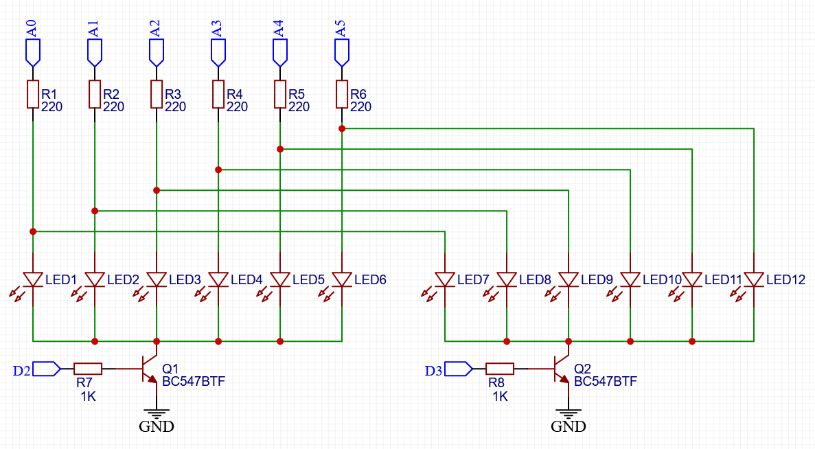
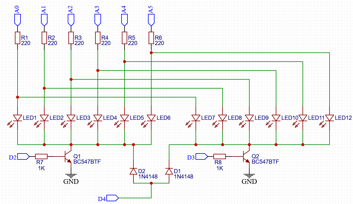
The circuit schematic has the LEDs driven by 6 pins on an Arduino plus two pins to activate one bank or the other. LEDs are these ones from LCSC.
My Arduino code lights up each bank of LEDs for around 1ms with its corresponding pattern. My test pattern consisted of turning on just LED7 for one second and then turning on LED6 for one second.
The Arduino code loops every millisecond and goes through the following:
- Turn off both banks
- Wait for transistors to fully switch off
- Place voltage on pins corresponding to LEDs that should turn on
- Turn on current bank
uint8_t mask[2] = {0b000000, 0b000001};

void setup()
{
  // Banks, through transistors
  pinMode(2, OUTPUT);
  pinMode(3, OUTPUT);

  // LEDs, through resistors
  pinMode(A0, OUTPUT);
  pinMode(A1, OUTPUT);
  pinMode(A2, OUTPUT);
  pinMode(A3, OUTPUT);
  pinMode(A4, OUTPUT);
  pinMode(A5, OUTPUT);
}


// Loop runs every millisecond or so because of the delay(1) near the end
void loop()
{
  static uint8_t pattern = 0;
  static uint32_t lastChangeTimestamp = 0;

  // Turn off both banks
  digitalWrite(2, LOW);
  digitalWrite(3, LOW);

  // Wait for transistor to fully switch off. This is not really
  // necessary when using digitalWrite() as this function is sooo slow
  // but would be required if we addressed ports directly
  delay(0.050);

  // turn off all LEDs
  digitalWrite(A0, LOW);
  digitalWrite(A1, LOW);
  digitalWrite(A2, LOW);
  digitalWrite(A3, LOW);
  digitalWrite(A4, LOW);
  digitalWrite(A5, LOW);

  // Turn on required LEDs
  if (mask[pattern] & 0x01) digitalWrite(A0, HIGH);
  if (mask[pattern] & 0x02) digitalWrite(A1, HIGH);
  if (mask[pattern] & 0x04) digitalWrite(A2, HIGH);
  if (mask[pattern] & 0x08) digitalWrite(A3, HIGH);
  if (mask[pattern] & 0x10) digitalWrite(A4, HIGH);
  if (mask[pattern] & 0x20) digitalWrite(A5, HIGH);

  // Activate required bank
  if (pattern == 0) digitalWrite(2, HIGH);
  else digitalWrite(3, HIGH);

  // toggle pattern
  pattern ^= 1;

  delay(1);

  // Every second switch the displayed pattern
  if (millis() - lastChangeTimestamp > 1000)
  {
    if (mask[1] == 1)
    {
      mask[1] = 0;
      mask[0] = 32;
    }
    else
    {
      mask[1] = 1;
      mask[0] = 0;
    }
    lastChangeTimestamp = millis();
  }
}
Ghosting
This sounded simple enough. But when tried out on a breadboard, in addition to the LED that I expected to have turned on I also had the corresponding LED dimly lit in the OTHER bank. That is, while I wanted LED7 and LED6 to alternate every second, I got LED7 bright and LED1 dim for one second, then LED6 bright and LED12 dim.
It's faint but enough to bug me.
Debugging
As stuff is happening every 1ms, first thing I did was slow it down. I went down to 1 second between changing banks to see exactly when the ghosting occurs. The unexpected LED gave a very brief flash whenever voltage was placed on the OTHER bank's LEDs (the bank with the legitimate LEDs). For example, when LED7 should turn on, LED1 also flashes briefly
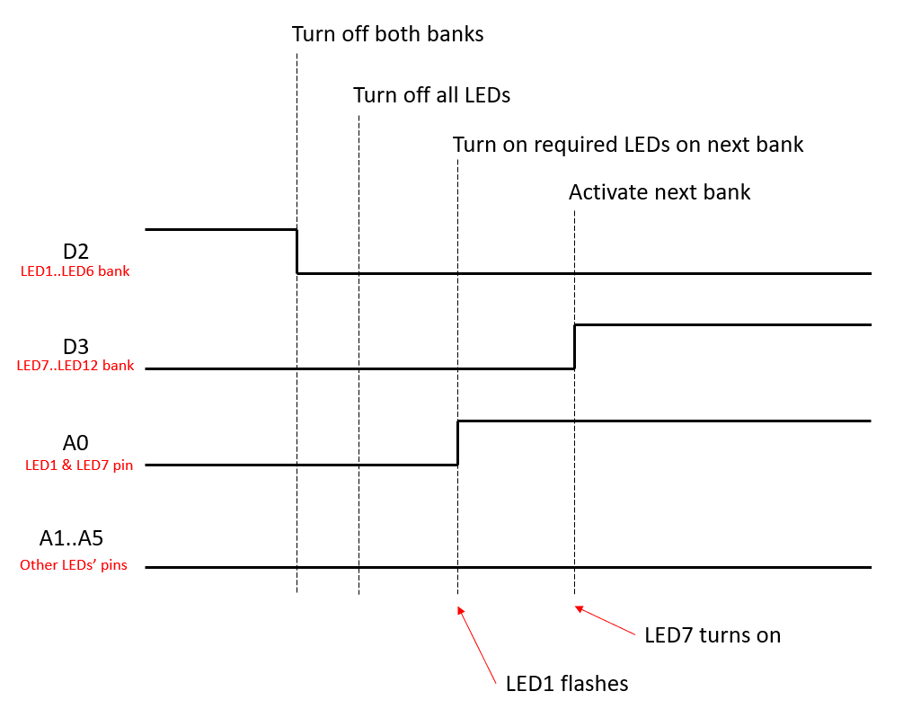
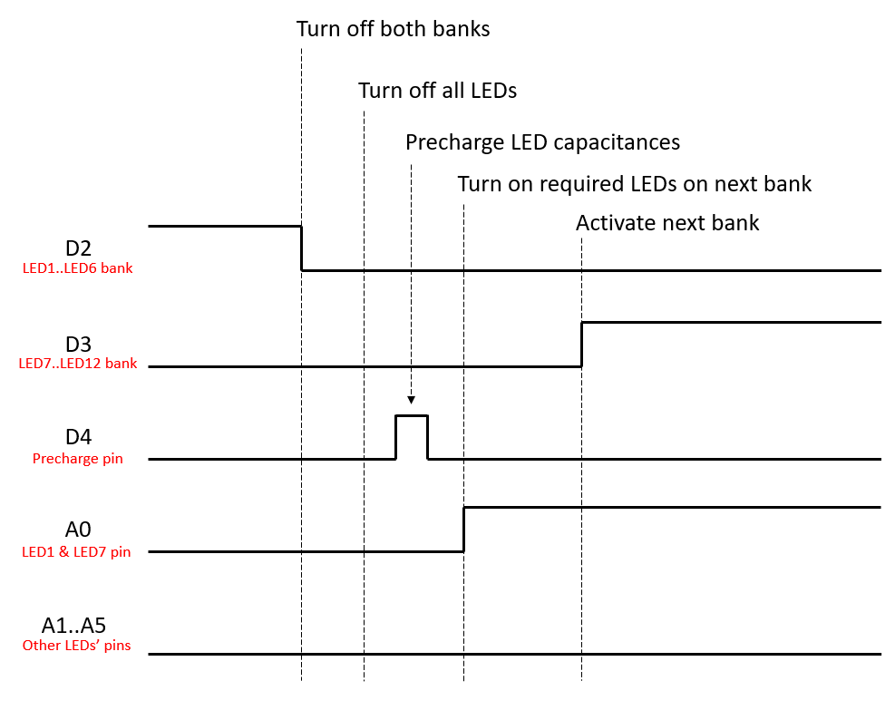
The timing diagram shows the transition from displaying LED1..LED6 (active with the transistor fed by the D2 line) to displaying LED7..LED12. After turning off both banks there is a delay to account for the transistor switch-off time and then all LEDs are switched off. Everything was already off so nothing changed here. Then line A0 goes high because in the next bank LED7 should be on. At this moment LED1 flashes briefly. Afterwards the bank containing LED7 is turned on by bringing line D3 high.
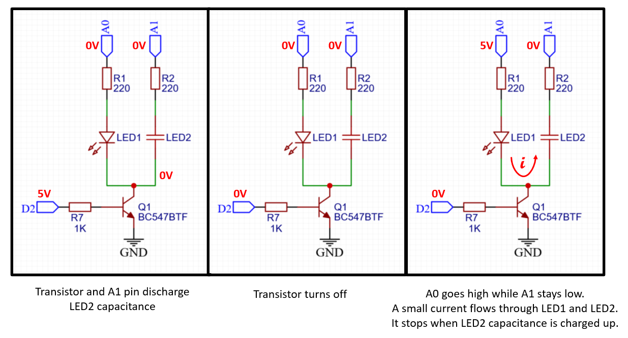
Simplifying the schematic just to the minimum number of components we need we can look at the steps the circuit goes through.
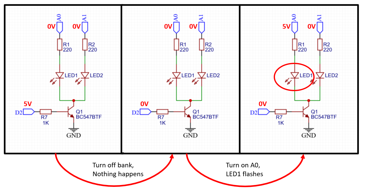
Only when A0 goes high LED1 flashes briefly. Were the transistor leaky, LED1 would stay dimly lit, not just flash. So it looks like a capacitor is charging. This suggests that LED2 behaves like a capacitor and a little bit of current goes through it until it charges.
LED capacitance
Diodes also have some capacitance and this write-up says that for a LED that is reverse biased at ~2.5V we can expect ~35pF capacitance.
Thus if we replace in the last schematic LED2 with a capacitor, the behaviour becomes more readily apparent.
Actually all other LEDs on the same bank do the same thing so their capacitances add up. Replacing in my circuit LEDs with 22pF capacitors produced identical behaviour.
Fixing it
In order to not have this happen the line connecting all LEDs in a bank needs to be precharged to ~5V before setting the individual LED voltages on their respective pins. To use a single pin I used diodes to precharge all banks, since this only happens when no bank is selected.
WARNING: Be careful with the timing, as you can damage stuff. If at any point you have D4 set high while you also have either D2 or D3 high there's nothing to limit the current from D4 to GND through the diode and transistor. As per Paul's suggestion, a current limiting resistor on the D4 pin should help.
And the corresponding timing diagram:
And the result!
Just for completeness, the Arduino sketch that includes the fix follows.
uint8_t mask[2] = {0b000000, 0b000001};

void setup()
{
  // Banks, through transistors
  pinMode(2, OUTPUT);
  pinMode(3, OUTPUT);

  // Precharge pin
  pinMode(4, OUTPUT);

  // LEDs, through resistors
  pinMode(A0, OUTPUT);
  pinMode(A1, OUTPUT);
  pinMode(A2, OUTPUT);
  pinMode(A3, OUTPUT);
  pinMode(A4, OUTPUT);
  pinMode(A5, OUTPUT);
}


// Loop runs every millisecond or so because of the delay(1) near the end
void loop()
{
  static uint8_t pattern = 0;
  static uint32_t lastChangeTimestamp = 0;

  // Turn off both banks
  digitalWrite(2, LOW);
  digitalWrite(3, LOW);

  // Wait for transistor to fully switch off. This is not really
  // necessary when using digitalWrite() as this function is sooo slow
  // but would be required if we addressed ports directly
  delay(0.050);

  // turn off all LEDs
  digitalWrite(A0, LOW);
  digitalWrite(A1, LOW);
  digitalWrite(A2, LOW);
  digitalWrite(A3, LOW);
  digitalWrite(A4, LOW);
  digitalWrite(A5, LOW);

  // Precharge by bringing LED rail high
  digitalWrite(4, HIGH);
  delay(0.01);
  digitalWrite(4, LOW);

  // Turn on required LEDs
  if (mask[pattern] & 0x01) digitalWrite(A0, HIGH);
  if (mask[pattern] & 0x02) digitalWrite(A1, HIGH);
  if (mask[pattern] & 0x04) digitalWrite(A2, HIGH);
  if (mask[pattern] & 0x08) digitalWrite(A3, HIGH);
  if (mask[pattern] & 0x10) digitalWrite(A4, HIGH);
  if (mask[pattern] & 0x20) digitalWrite(A5, HIGH);

  // Activate required bank
  if (pattern == 0) digitalWrite(2, HIGH);
  else digitalWrite(3, HIGH);

  // toggle pattern
  pattern ^= 1;

  delay(1);

  // Every second switch the displayed pattern
  if (millis() - lastChangeTimestamp > 1000)
  {
    if (mask[1] == 1)
    {
      mask[1] = 0;
      mask[0] = 32;
    }
    else
    {
      mask[1] = 1;
      mask[0] = 0;
    }
    lastChangeTimestamp = millis();
  }
}
Conclusions
While I have multiplexed LEDs like this in the past, this is the first time I encounter this issue. My guess is as LED technology gets better, they're getting faster and need lower currents to start emitting considerable amounts of light.