Why Servo Motors?
Servo Motors are used in a variety of fields. These are mainly used as actuators in those areas where we need a precise movement to control output load.
The best example is an RC car. Let's see you want a movement of 45 degrees, not more not less. In that case, you can't use a simple DC motor because it will overshoot the desired position every time you power it up.
And thus we need a Servo Motor to achieve this task as it will not only make a precise 45-degree rotation but will also stop smoothly at the desired position.
There are many types of servo motors and their main feature is the ability to precisely control the position of their shaft. A servo motor is a closed-loop system that uses position feedback to control its motion and final position.

Technicalities of a Servo Motor
You must know what's inside it and how it works. a servo motor is made up of three key components:
- A DC motor
- Gearbox
- Potentiometer, either analogue or Digital
- Control circuit
There are total 3 wires that come out of a Servo Motor:
RED: To positive of the supply
- BLACK: To negative of the supply
- ORANGE OR YELLOW: Connected to a reference voltage i.e., a PWM source
Servo Motor can rotate 90 degrees in either direction, covering a maximum of 180 degrees i.e., either 90 degrees clockwise or 90 degrees anticlockwise from its neutral position.
How does it work?
The DC motor is a high speed and low torque but the gearbox reduces the speed to around 60 RPM and at the same time increases the torque.
The potentiometer is attached to the final gear or the output shaft, so as the motor rotates the potentiometer rotates as well, thus producing a voltage that is related to the absolute angle of the output shaft. In the control circuit, this potentiometer voltage is compared to the voltage coming from the signal line. If needed, the controller activates an integrated H-Bridge which enables the motor to rotate in either direction until the two signals reach a difference of zero.
A servo motor is controlled by sending a series of pulses through the signal line. The frequency of the control signal should be 50Hz or a pulse should occur every 20ms. The width of the pulse determines the angular position of the servo and these types of servos can usually rotate 180 degrees (they have a physical limit of travel).

Generally, pulses with 1ms duration correspond to 0 degrees position, 1.5ms duration to 90 degrees and 2ms to 180 degrees. Though the minimum and maximum duration of the pulses can sometimes vary with different brands and they can be 0.5ms for 0 degrees and 2.5ms for 180 degrees position.
Controlling the Servo Motor using 555 Timer
Usually, a microcontroller like Arduino is used to control the servo motor. But, for the basic understanding of the working of the servo motor, we will use a 555 timer here.

CIRCUIT WORKING:
1. When the forward push button is pressed
When this case arises then a 68 K resistor get connected between discharge and threshold pin. Now initially capacitor is not charged so pin 2 is at 0 volt which is less than 1 by 3 of applied voltage.
This resets the flip flop inside the 555 and gives logic 1 at the output terminal at which the base of the transistor is connected.
This causes the transistor to turn on and conduct current directly to the ground due to which signal pin of motor get zero volt as this pin is directly connected to Collector terminal.
Since the capacitor starts charging when output is 1, the output becomes 0 as soon as the voltage across the capacitor becomes greater than 2 by 3 of applied voltage as it is directly connected to the threshold pin.
Now the transistor will be off and the signal pin will get logic 1.
In this way, PWM signals are generated at the reference pin of the motor. Now in this case on the time period of generated pulse is greater than 1.5 milliseconds, which you can calculate by the duty cycle formula for 555. And thus we get 90-degree clockwise rotation of the motor as explained in the above paragraph.
2. When the backward push button is pressed
When this case arises then a 10 K resistor get connected between discharge and threshold pin which is less than 68k ohm resistor. Thus in this case the on-time period of pulse is lesson than 1.5 milliseconds, which you can calculate by the duty cycle formula for 555.
Now the PWM is generated at the reference pin of the motor the same way as in the above case. And thus we get 90-degree anticlockwise rotation of motor as explained in the above paragraph.
**in both the cases frequency is between 40 to 60 hertz
Putting all the stuff together

Follow the below steps to assemble the device at home easily:
- Download the Gerber files for the PCB from here or down below.
- Go to PCBWay.com and upload the files get your PCBs at home at a very low price. Also, you can get a $5 Welcome Bonus. They are the most cost-effective and quality-oriented PCB manufacturers. You can order your prototype PCBs in a small quantity, as small as 5 pcs of PCB. In addition to the standard PCBs, we could also support advanced PCBs, FPC/rigid-flex PCBs, and other related services.
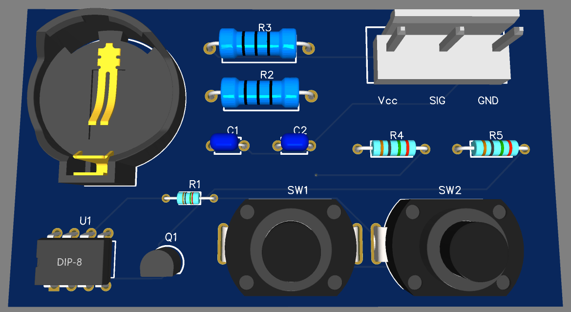
- Solder the components on the PCB as per the schematic and design shown below.
- Connect the battery and servo motor's connection to the headers.