Glenn.Kubota (gee.k)
The Menorah555 assembly consists of three main parts: the printed circuit board assembly (PCBA), the LED flame diffusers, and the bent acrylic base. Details (excruciating) on each of those follow.
PCBA
The Menorah555's schematic and PCB were designed in KiCad 5.1.12. There are only a few different parts to the schematic since much of it is repeated for the eight non-shamash candles.
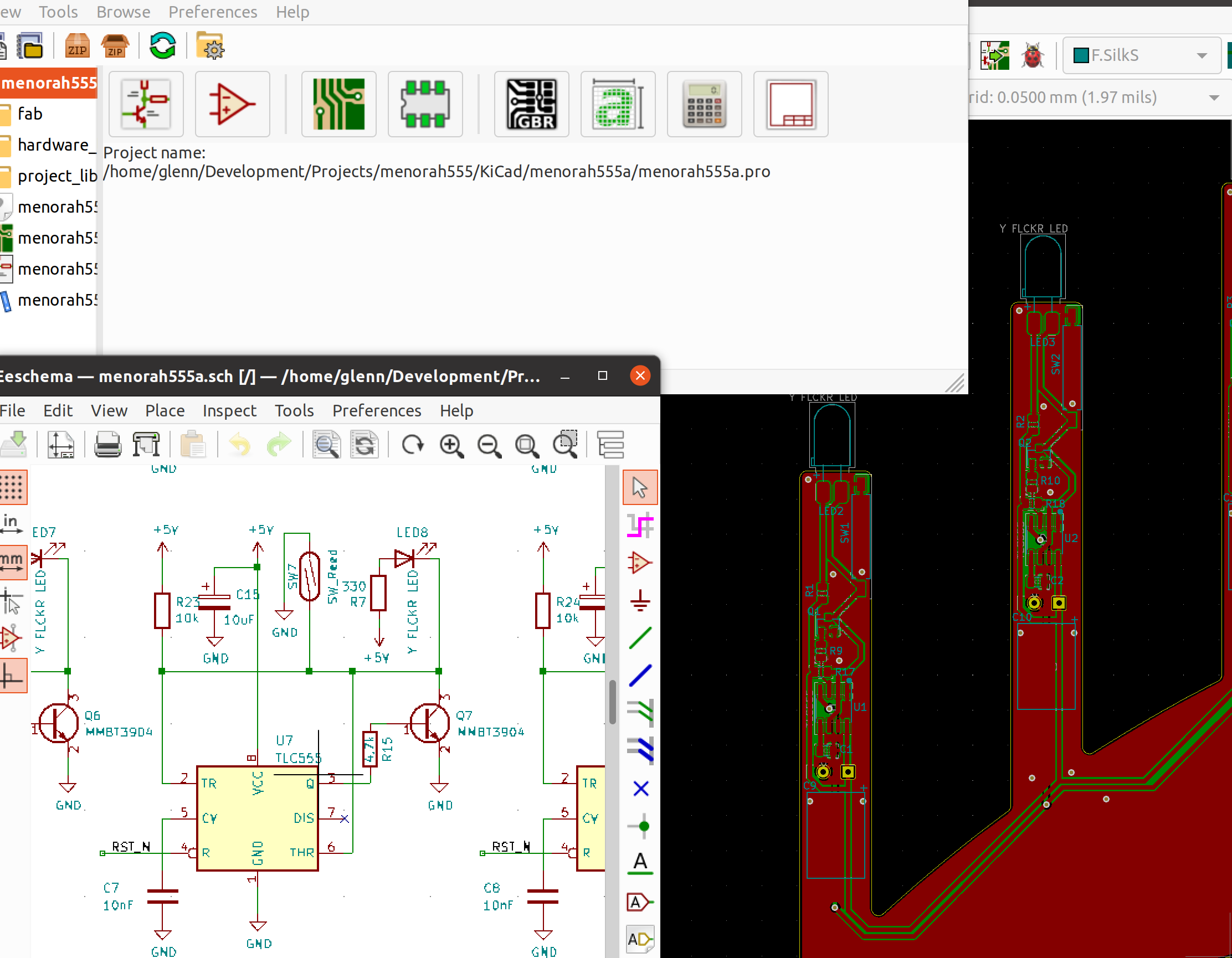
The main parts of the schematic include the shamash, current limiter, candles, and power-on reset.
Shamash
The shamash candle, like all the other candles, is designed with an LED that looks like a standard T-1 3/4 LED with a 5-mm diameter, but it actually has a chip inside that applies PWM to the LED in a way that simulates a flickering candle. Using this type of LED eliminates the need to use a separate microcontroller to create that effect. A 330-ohm resistor is put in series with the LED to limit the current and set the brightness.
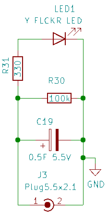
Since the shamash is removed and used to "light" the
other candles, it needs a power source to keep it lit during that
time, maybe 30 seconds. That role is filled by a 0.5-F
supercapacitor. That is 0.5 farads, not microfarads,
so it holds a LOT of charge. In fact, this holds way more than
necessary, but I wanted a capacitor that would lay flat to give the
suggestion of a cylindrical candle shape. This supercap charges in a
couple of seconds, but actually keeps the LED lit for 10 minutes
before it gets noticeably dim and is still very dimly lit at 20
minutes, so you can really take your time lighting the other candles!
A common barrel-style power connector was used so that the shamash PCBA can be unplugged from the mainboard and used to light the other candles.
Current Limiter
The menorah has a micro-USB connector so that it can be powered with a USB charger or battery pack. These power supplies are designed to supply at least 500mA, although they may supply more. However, the inrush current on the 0.5F supercap may be much more than that and it could send the power supply into an over-current condition. Since this is undesirable, a current limiter circuit was added to prevent this.
This current limiter is not very precise, but there is no need for great precision because we don't need an exact current, as long as it's less than 500mA.
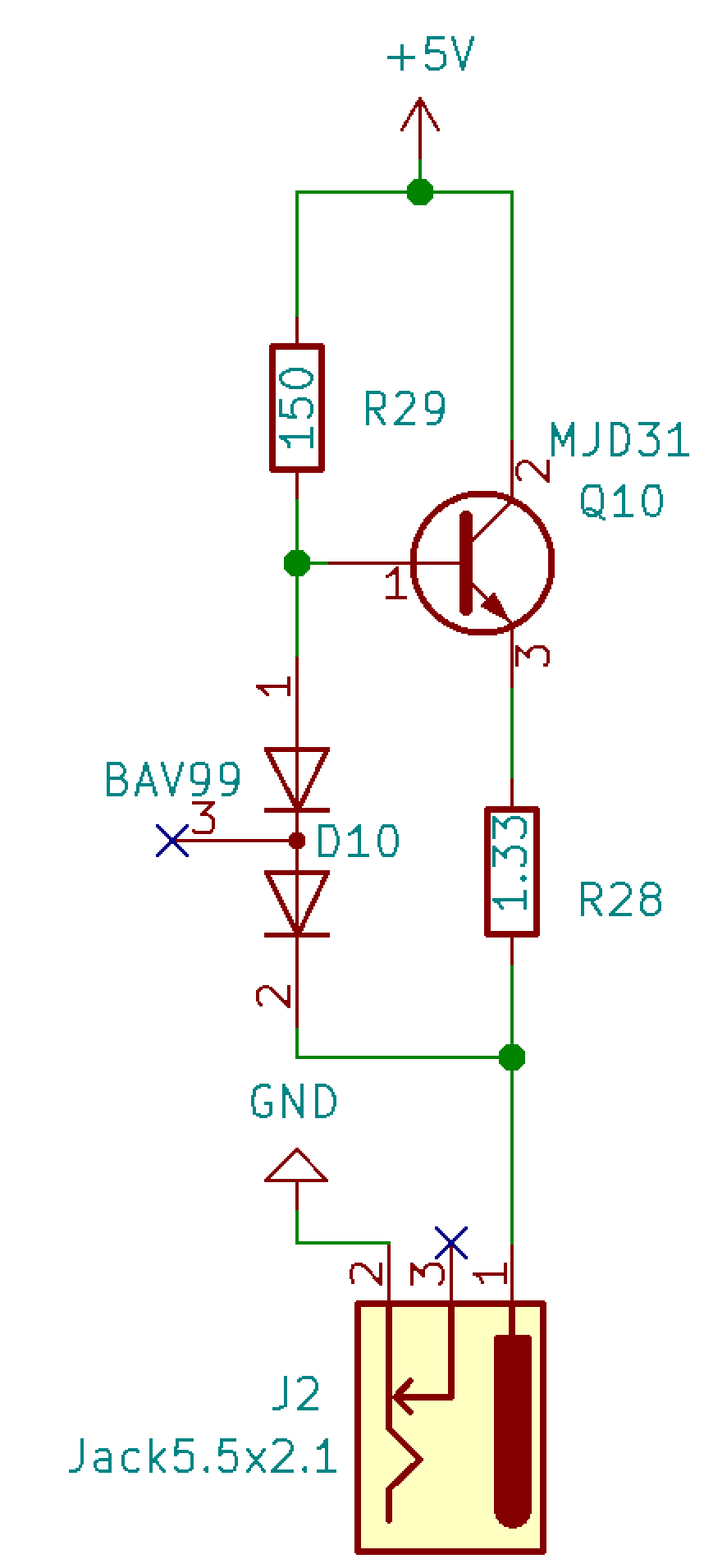
The current limit is set by the value of the current-sense resistor, R28, which is 1.33 ohms. When power is first turned on, the base of transistor Q10 is biased by R29, which turns on Q10 and allows a larger current to flow through Q10 from collector to emitter. The current flows through the current-sense resistor to the shamash supercap, which begins charging.
When the supercap first begins charging, it is essentially a dead short, except for its equivalent series resistance. If the current through the 1.33-ohm resistor R28 reaches ~450 mA or more, the voltage drop across R28 is above 0.6 V. When combined with the ~0.6 V voltage drop across the Q10 base-emitter junction, this means that the total voltage drop is more than 0.12 V and is enough to turn on the two diodes in D10. When D10 starts conducting, it reduces the current going into the base of Q10, which reduces the current going into the collector. Thus, the current ends up getting regulated so that i = V/r = 0.6V/1.33Ω = 450mA, give or take a bit. This will vary due to temperature variations and tolerances, but that’s close enough.
The current through a capacitor follows the equation i=C dV/dt, so when the capacitor is charged with a constant current, dV/dt = i/C = 450mA/0.5F = 0.9V/s. Thus it only takes a couple of seconds before the supercap is charged enough to turn on the LED.
Candles
The candle circuit (duplicated eight times) has more parts than it needed because I started to add another feature, but I needed to place an order for PCBs if I wanted them to arrive before Hanukkah was over. Thus, when it came to a choice of minimizing the BOM or maximizing the features, or having the menorah for this year’s Hanukkah, I chose to order the PCBs as-is. Anyway, I will explain the circuit as it is, not as it could have been <sigh>.
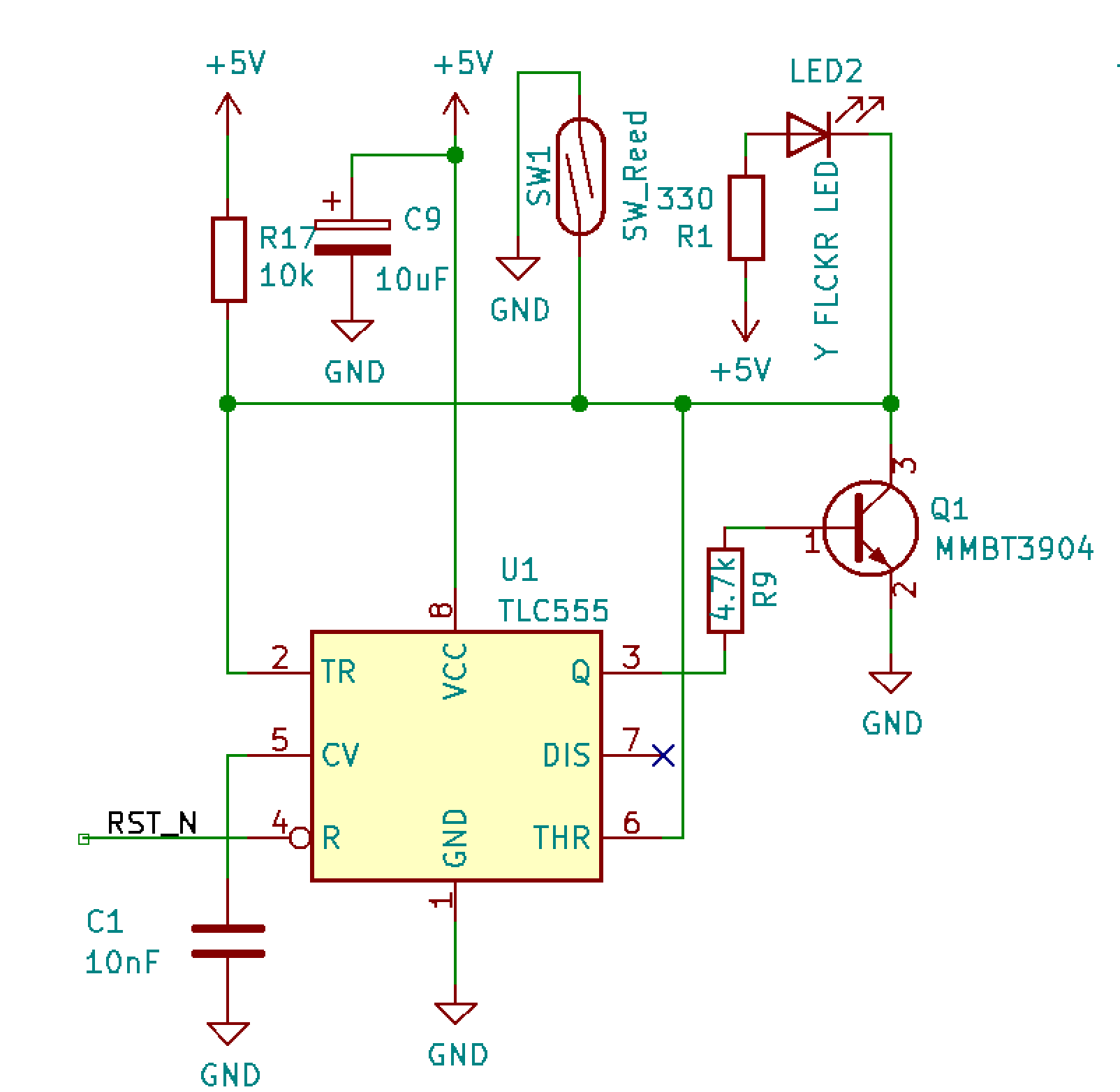
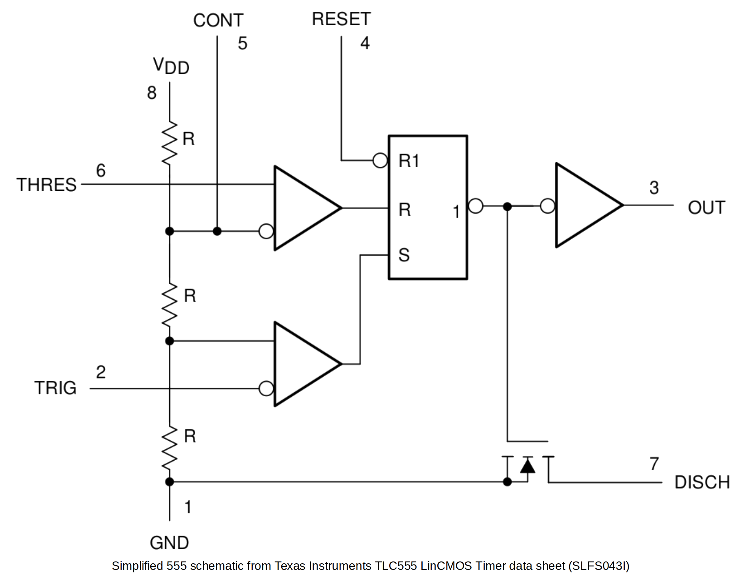
The circuit is designed around a woefully underused 555 timer being used as a latch. There is absolutely no timing being done here! When the system is powered up, the reset line RST_N on pin 4 (RESET or R) goes low and clears the SR flip-flop so that pin 3 (OUT or Q) goes low. R17 pulls up pins 2 (TRIG or TR) and 6 (THRES or THR) so the SR flip-flop is kept in the reset state because R is high and S is low.
When the magnet on the shamash is brought near the reed switch SW1, it pulls pins 2 and 6 low. The SR flip-flop now has S high and R low, which causes pin 3 to go high. This turns on transistor Q1, which continues to pull pins 2 and 6 low even after the magnet is taken away from the reed switch. The LED is also lit when its cathode is pulled low and it emits its sweet flickery luminescence. This state is stable and the only way to change the state back is to assert the reset line again.
Now each of the eight 555 latches is bypassed with a ridiculously over-the-top 10uF 200V electrolytic capacitor. This was done for aesthetics because they were cylindrical and about the same length as the supercap on the shamash.
Power-on Reset
The power-on reset
circuit is also designed around a 555 timer, which is used for . . .
timing! Yes, this could have been a supervisor chip instead,
but why not use
another 555? That's nine 555 timers altogether, although I may add some more on another board spin.
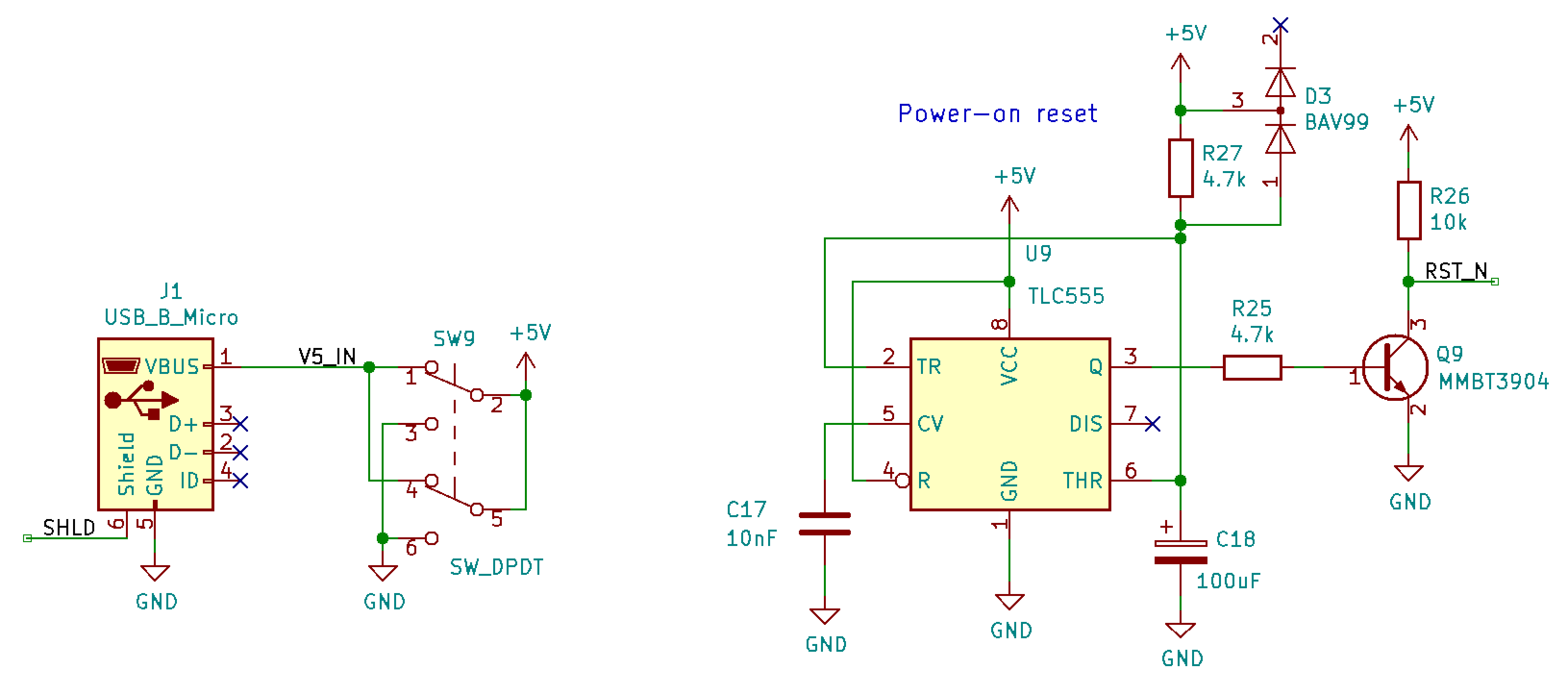
When the power switch SW9 is in the OFF position, it disconnects 5 V from the power rail but also shorts the +5V power rail to GND to make sure it is really really OFF. When in this position, any charge on the 100 uF capacitor C18 is discharged through D3.
When the power switch is changed to the ON position, the +5V rail rises quickly, but pins 2 (TR) and pins 6 (THR) take a while to rise because it takes a while for C18 (100 uF) to charge through R27 (4.7 kΩ). When the voltage across C18 is less than 1/3 of the +5V rail, the SR flip-flop in the 555 is held in the Set state, so pin 3 (Q) is high. This turns on Q9, which pulls the RST_N signal low, resetting all eight of the 555 timers on the candles. As the voltage across C18 rises above 1/3 of the +5V rail, the SR flip-flop has neither S nor R asserted, so it holds the Set state, which still keeps RST_N low. Finally, as the voltage across C18 rises above 2/3 of the +5V rail, the SR flip-flop changes to the Reset state, so pin 3 (Q) goes low. This turns off Q9, which causes RST_N to be pulled high by the R26 pull-up resistor.
The voltage across a capacitor (Vc) being charged through a resistor (R) follows the equation:
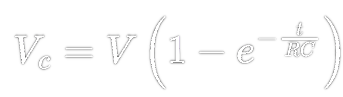
so the time for the voltage Vc to reach
2/3V can be reduced to t=ln(3)RC or about 1.1RC. With a 4.7k
resistor and 100uF capacitor, that means the reset time is about 0.5
s.
LED Flame Diffusers
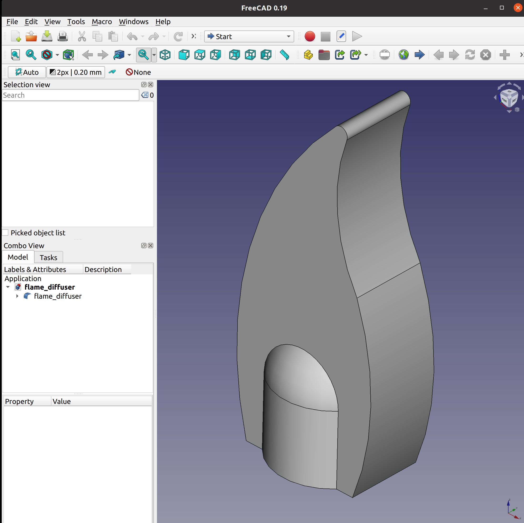
The
LED flame diffusers were designed in FreeCAD 0.19. The purpose was to
diffuse the light from the LEDs and to also give the look of a
stylized flame. The design was then exported to an STL file, sliced
with Ultimaker Cura 4.12.1 (no support material needed), and printed on a
Creality Ender 3 Pro with transparent PLA. The resulting prints were mounted
onto the LEDs with an interference fit that did not require any
adhesive. Layer lines and fill patterns actually help to diffuse the light.
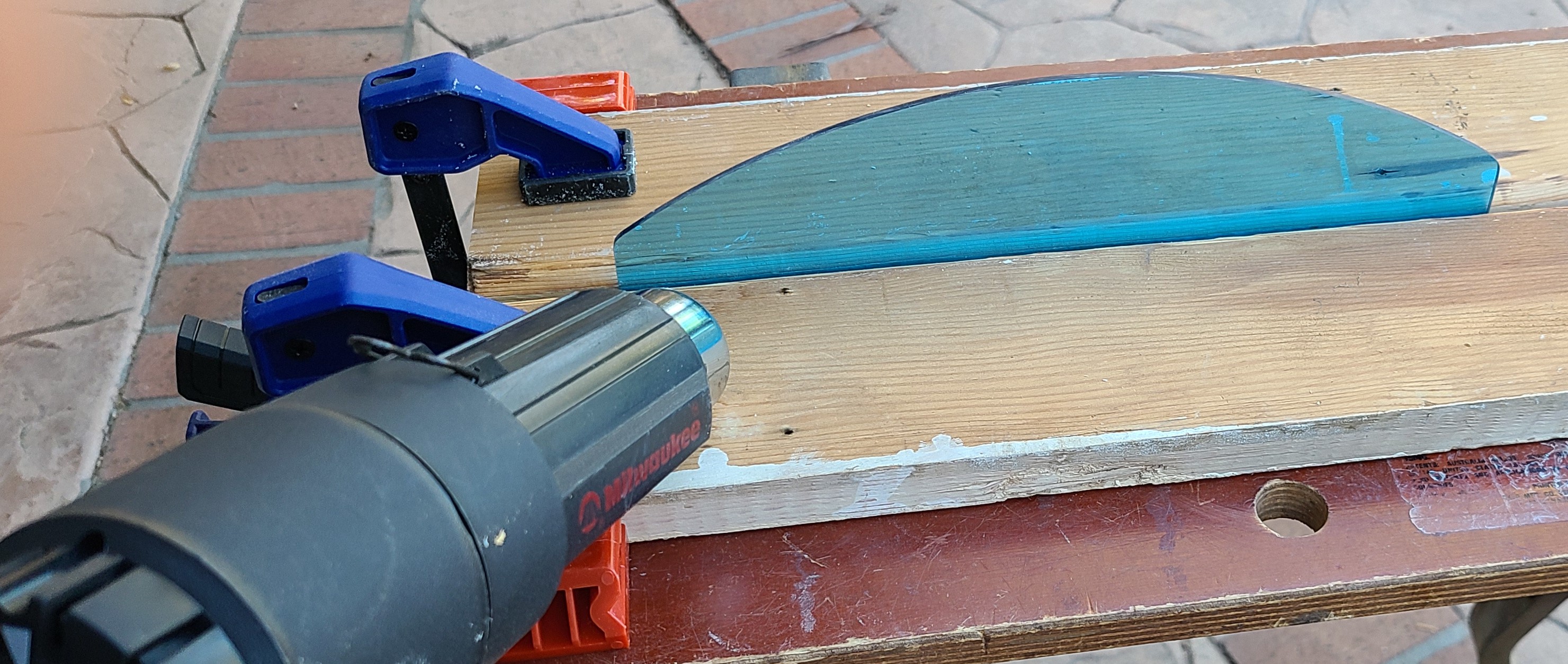
Acrylic Base
The base of the menorah was also designed in FreeCAD 0.19. The base was fabricated from transparent 3-mm thick blue acrylic.
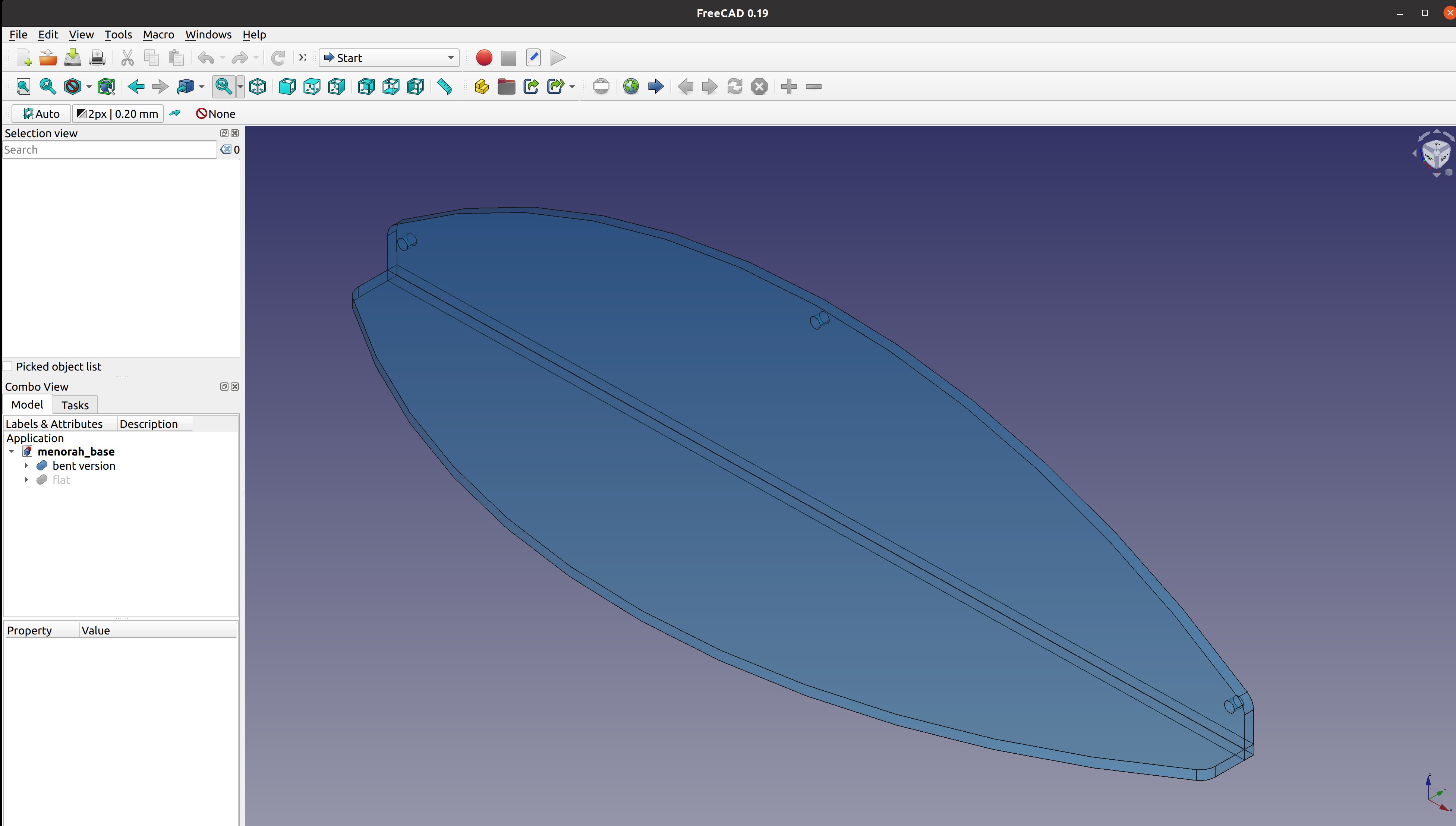
It would be easiest if this were laser cut, but since I have no access to a laser cutter, I used a jigsaw to cut the shape and then sanded and polished the edges. Bending was accomplished by using a heat gun to apply heat to the desired area and then bending to 90 degrees.