 KSUdoubleE
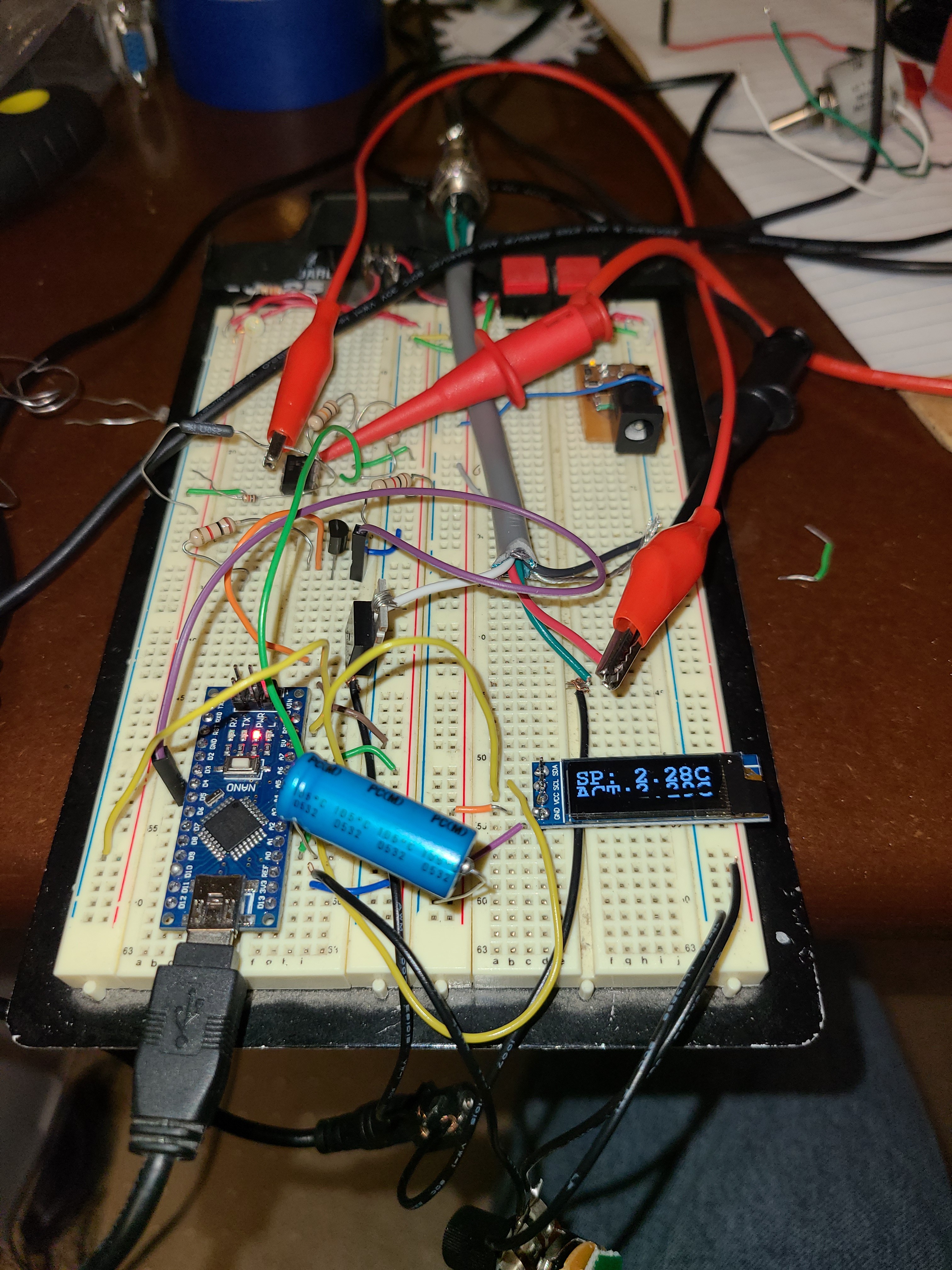
I've breadboarded the circuit to check everything out. Things look good, but I'm seeing something weird with the thermocouple resistance on the voltage divider going into the OpAmp circuit. When disconnected to anything else, I am seeing about 1-2ohms on the TC resistance when at room temperature. Using a IR temp gun (best thing I have to get an idea, I don't have any other high temp TCs), when disconnected from the voltage divider, I see about 20 ohms at 400 C. Using a 250 Ohm resistor connected to 5V and the one leg of the TC and the other leg of the TC to ground, I would expect to see 0.37 VDC in the middle of the divider at 400C. I am seeing about .051 VDC. At room temp connected with the 250 Ohm divider circuit, I should see .029 VDC but I am metering .02 VDC. When I check the resistance of both the 250 Ohm and the TC, they are behaving properly, but hooked together with 5V to ground, I get different results. The results are still linear, meaning that as the iron heats up the measured voltage on the divider predictably corresponds with the temperature observed. Maybe the less than stellar connections of the breadboard are causing issues? Either way, I think I can make this circuit work, I will just have to change the amount of gain on the op amp circuit to get good resolution in the Nano's ADC. I am going to fabricate my own PCB next and see what I see.
As a positive, the other parts of the circuit are working as expected. The MOSFET drive and MOSFET are switching the iron on and off as expected and I have the display hooked up and working. The potentiometer should work fine for setpoint. I will probably even use this breadboarded circuit to solder up the PCB for the project.
Discussions
Become a Hackaday.io Member
Create an account to leave a comment. Already have an account? Log In.