 Shranav Palakurthi
I finally got the time to code the ATTiny555 so that it works using a flipped and rotated chip, making it a near-perfect pin-compatible drop in for the real 555.
With this change, I was able to trade The Gotcha (the ground and reset pins being switched) for a smaller, almost unnoticeable catch (the control pin being connected to VCC). In most 555 timer circuits, the control pin is isolated to ground via a filtering capacitor, meaning that it could be at any reasonable voltage without causing problems. However, for the situations where you might need the control pin, take a long look in a mirror and ask yourself why you're entertaining the idea of using a microcontroller to genuinely replace an existing 555 timer.
For my sanity, and yours.
Anyways, this new version is now 100% pin compatible with a 555, and depending on the application, a drop-in replacement for the real stuff!
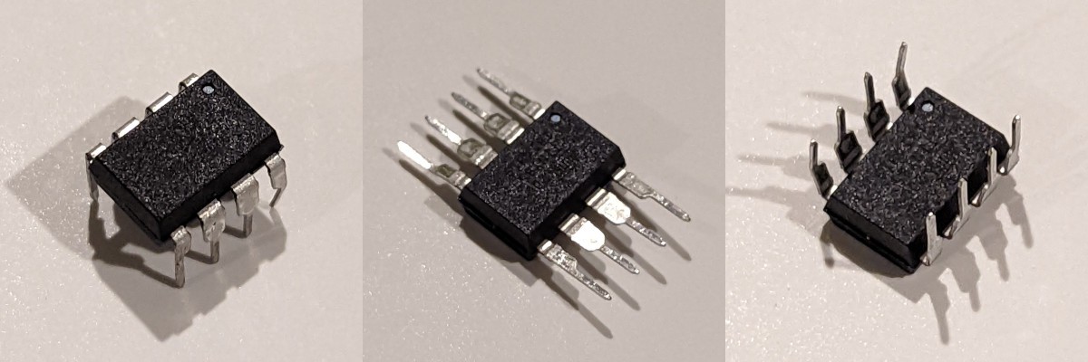
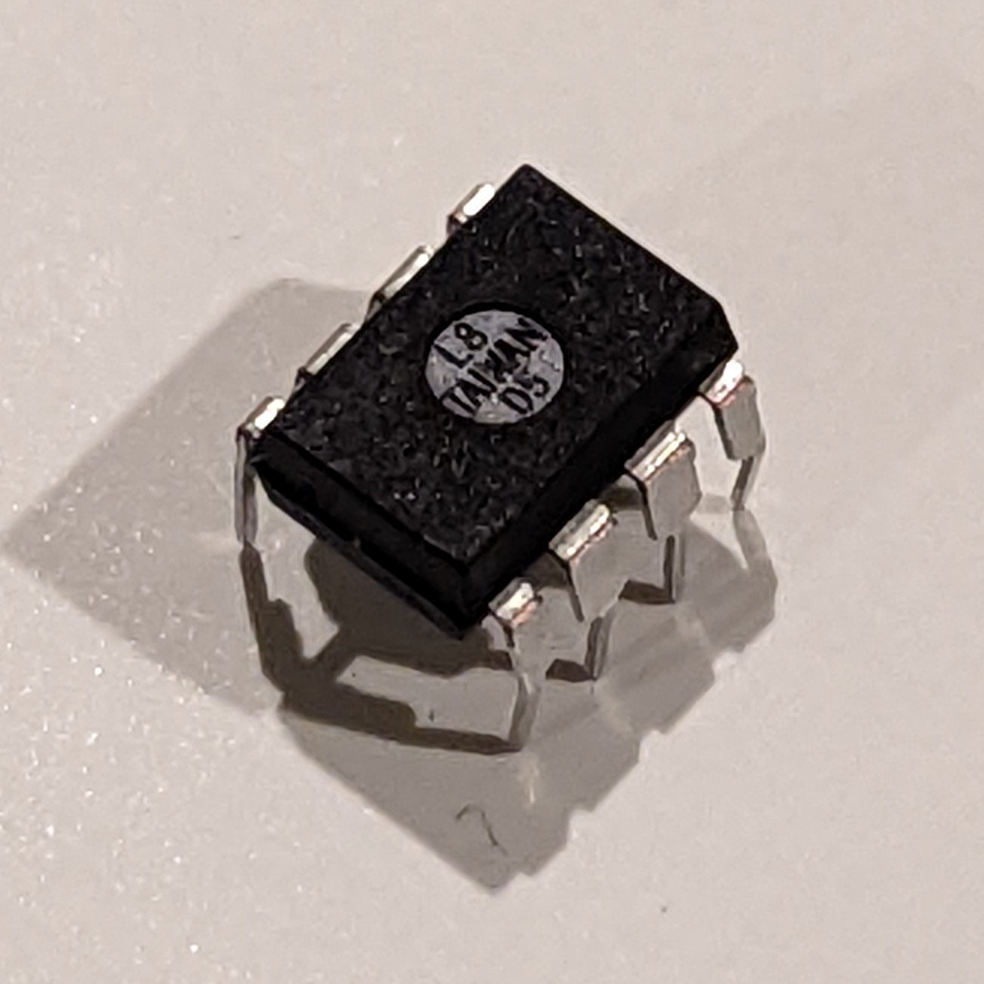
Here's an ATTiny85 running the new code, pre-operation.
With the code verified, it was time to make it a real 555! Hand me my scalpel, I'm going in.
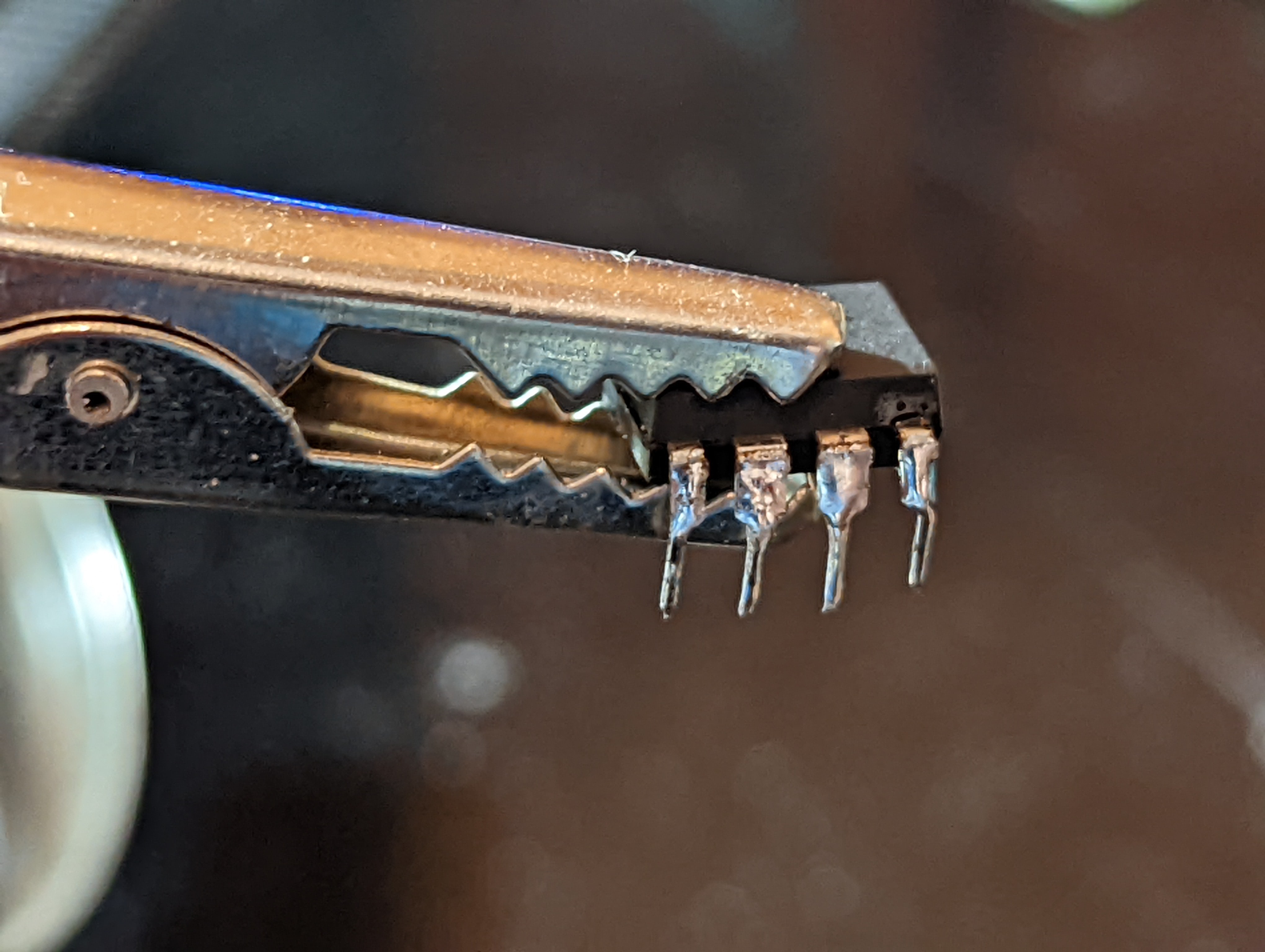
To do this, I had to bend the chip's pins backwards...
Unfortunately, this caused some cracking near the pin's bases, which I tried to solve by filling them with solder.
With limited success, unfortunately.
Ignoring that mechanical flaw, I bridged what used to be PB0 with the VCC pin using a cut resistor lead I had laying around.
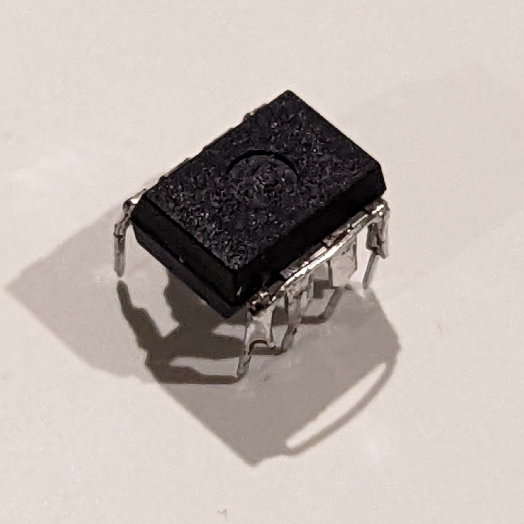
And there it is! An ATTiny555 in all of its (limited) glory. No external components required!
Discussions
Become a Hackaday.io Member
Create an account to leave a comment. Already have an account? Log In.