Some design goals:
- Use a 555 central to the design, with minimal additional circuitry.
- Keep it simple. A real-life implementation should add under voltage lockout for the load and over and under-temperature lockout for charging, but adding these would obscure the simplicity of the basic charging circuit.
- My design is for LiFePO4 batteries (3.6V max) but with some resistor changes it can be altered for LiPo (4.2V max, but not recommended as charge current is not regulated) or Lithium Titanate (LTO 2.8V max).
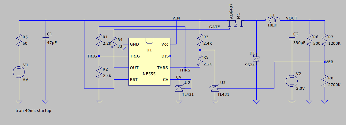
An LTSpice simulation circuit is shown below:

Notes about the schematic:
- V1 and R5 simulate a "weak" power source with high internal resistance, such as a solar panel.
- C2 and V2 are a model for a very low capacity battery, starting at 2V.
- R6 represents a load.
- The rest of the circuitry is the actual charger circuitry.
- This doesn't do Maximum Power Point Tracking (MPPT) but simple MPP with a pre-set voltage, which means the charger will not allow the input voltage to fall below a certain level, this voltage should be configured to the MPP voltage of the solar panel.
- There is no charge current limiter, limit the charge current by using a small enough solar panel that doesn't have the power to provide a current too high for the battery. :)
- The 555 is used as a comparator with hysteresis that drives the power MOSFET M1 which, together with D1, L1, and an output cap (combined here with "battery" C2) makes up a buck converter.
- Since the solar panel MPP voltage and the battery "full" voltage require absolute voltage levels, and the 555 is ratiometric and knows nothing about absolute voltages, we add two references U2 (for MPP level, biased through the 555's internal 5K resistive divider) and U3 (for battery full level, biased through R3) to be able to detect these voltages.
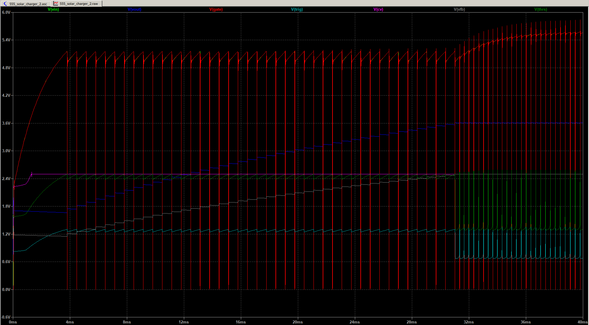
Below is a simulation trace:

At the very beginning of the trace, the input cap C1 is charging, and the circuit is not switching because the input voltage is below the MPP voltage, which in this circuit is set to ~5V. Once 5V is reached, the switcher built around the 555 starts. There is no timing cap in the circuit, the timing is derived from the input voltage going above MPP level (THRS rises above CV) and falling below the MPP level (TRIG goes below CV/2). The hysteresis is created by R1 and R2 having slightly different values. The actual switching frequency is dependent on incoming power, input cap size, output cap size and load).
As you can see in the trace, from 4 to ~30 ms, the input voltage stays around the MPP level of 5V, and the output voltage (the blue trace) goes up as the "battery" charges.
When the output voltage reaches 3.6V (battery full level for LiFePO4), the voltage VFB generated by divider R7/R8 reaches 2.5V, which makes reference U3 conduct. This pulls THRS low, preventing its voltage level from going above CV and this prevents M1 from being turned on, effectively causing charge termination.
So why do we still see switching after ~30 ms? Because load R6 is discharging the battery, so the voltage drops below 3.6V which re-enables the switcher. As you can see, the input voltage is not held at around 5V anymore but is allowed to go higher, switching just happens as needed to keep the voltage stable at 3.6V.
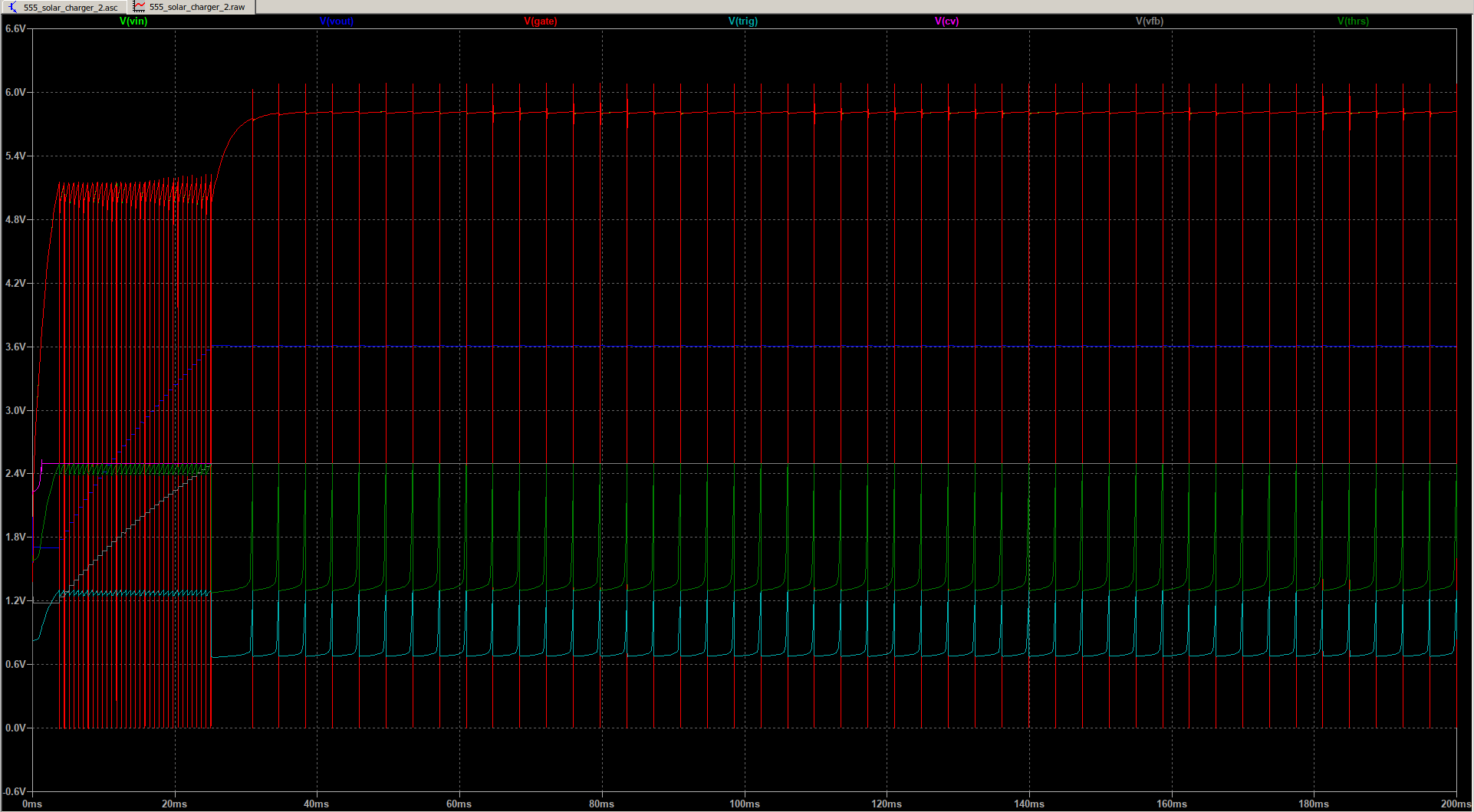
In the trace below, we have increased the load by a factor 1000x to 500K:

Because it is not being discharged while also charging, the small battery reaches the "full" level of 3.6V much quicker, and because the load is low, there are much less switching cycles when the battery is full because it is being discharged much slower.
If using a LiFePO4 cell, the battery voltage can be used to power 3.3V circuitry directly, IF the circuitry goes into a low power mode when the voltage falls below 2.9V or so to prevent the battery from over discharging.
If a different "full" voltage for the battery is desired, divider R7/R8 can be adjusted accordingly.
R3 can be adjusted to set a different MPP voltage for the solar panel you use. You can calculate R3 this way for a desired MPP voltage: R3 = (VMPP * (R1 + R2) / 2.5) - (R1 + R2 + R9)
I hope you enjoy this unusual, "creative" use of a 555 timer in a useful circuit!
 Patrick Van Oosterwijck