 Matej Gurnak
Recent achievements:
Battery build:
Orthophotomaps:
| Simple map | Area measurements | Map with elevation data |
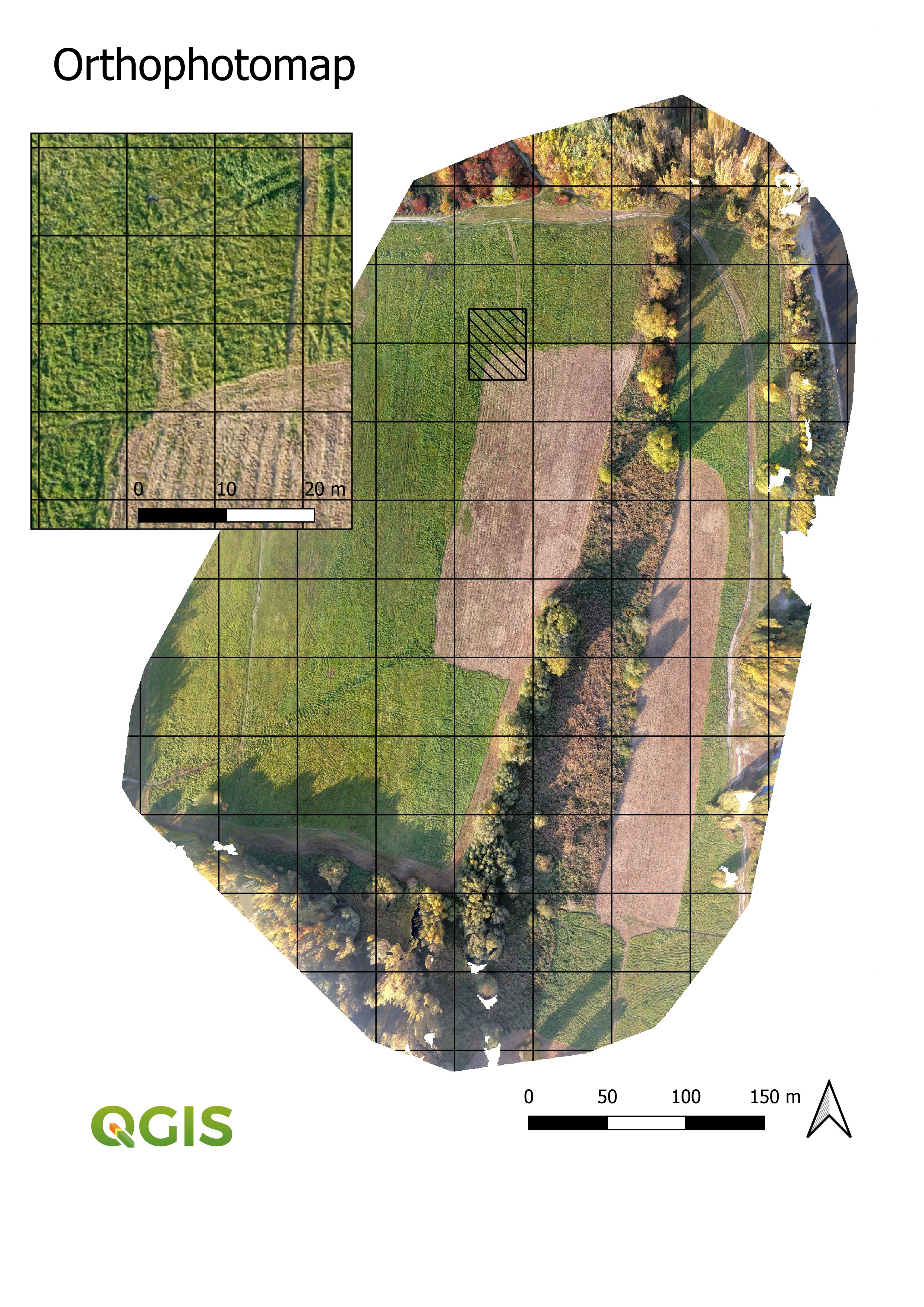 | 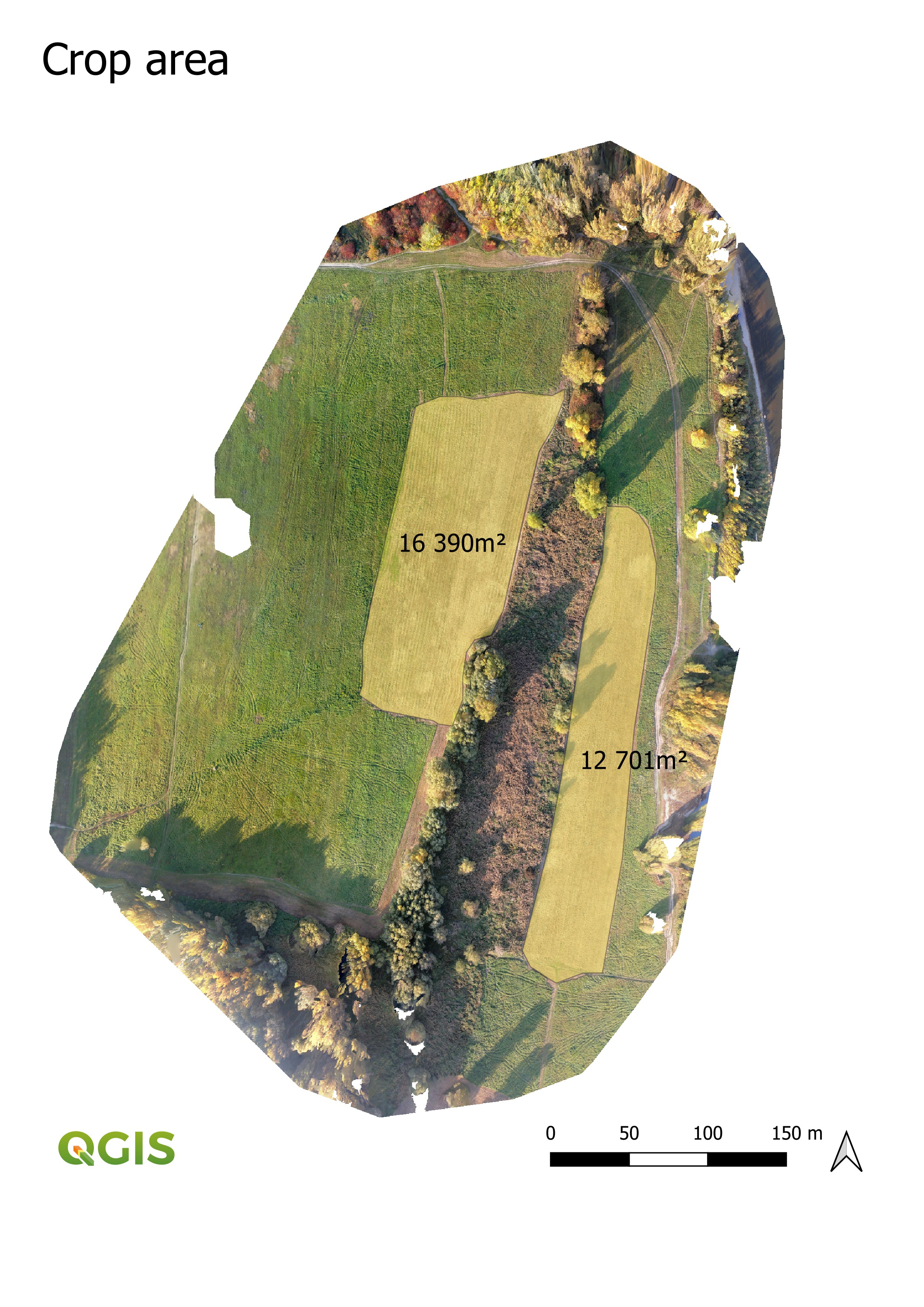 | 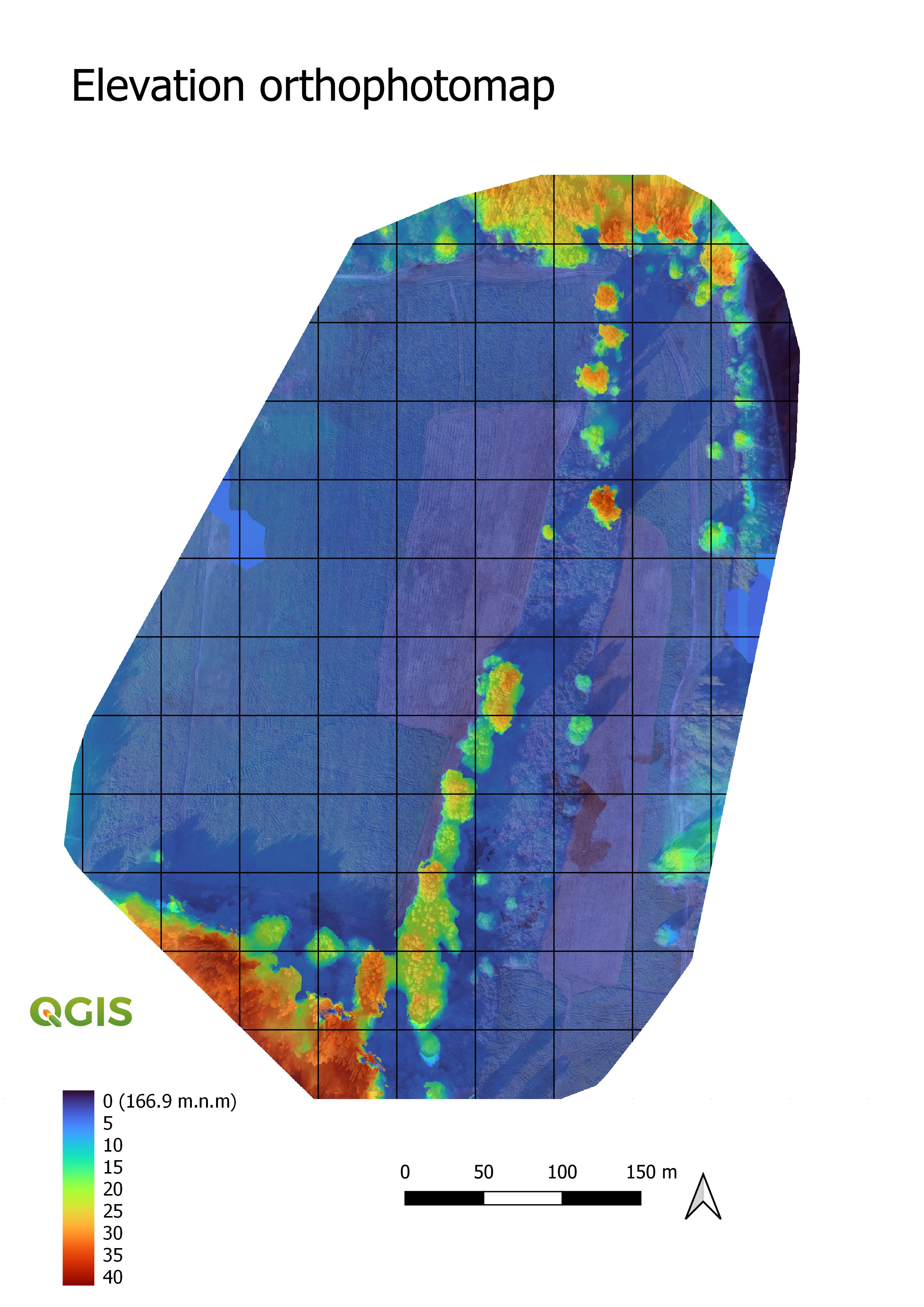 |
Endurance flight:
Project:
As the name of the project implies, I wanted to come up with a free-to-share UAV concept for a capable plane that everyone can build on their own and experience the thrill of making something.. There are no universal design options in engineering, so my first task was to determine the possible use cases and define the design features based on those.
 |  |
One can find many advanced UAV systems on the market, however, they tend to be very expensive and are therefore not affordable for individuals.
It would be near impossible to try to compete with them in any other area other than price. Though this wouldn't be possible without sacrificing functionality, reliability or usability. The cost of professional UAV systems also includes research and development, which is something one can’t put a price on. Nevertheless, we also benefit from this. New technologies eventually become cheaper and more accessible, and now even hobbyists have the access to cutting edge hardware like flight controllers, and also software.
Whilst there are limitations to what you can achieve with this project in comparison to commercial UAVs, you most likely won't stumble upon a use case that is not at least partially covered or possible with this project.
Use cases:
- Long flights - one hour and more
- Close range - reliably up to 3 - 5 kilometers (even more with better components)
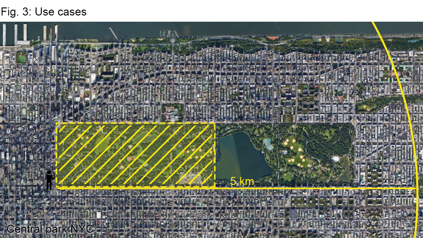
- Great coverage - 150 - 200 ha (2x10⁶ m²) - equivalent to about 0.58 - 0.77 square miles or half of Central Park
- Mapping, monitoring, test platform for beginners in autonomous UAVs, educational platform for students, (delivering), (fpv flying)
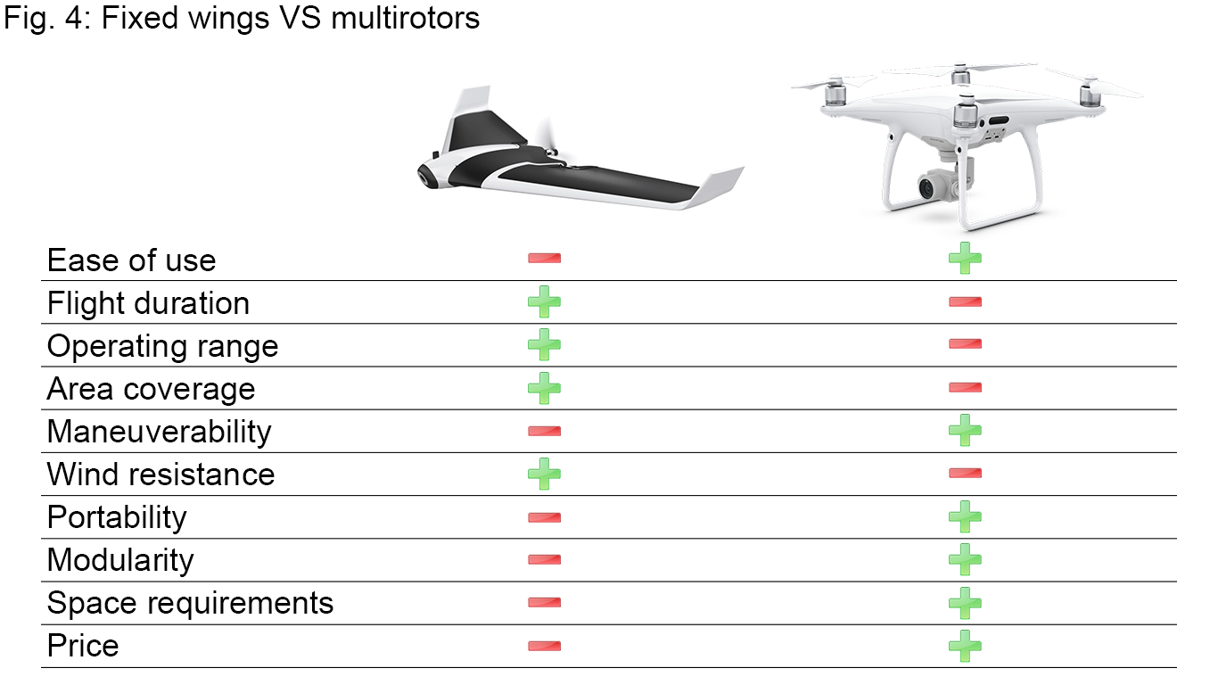
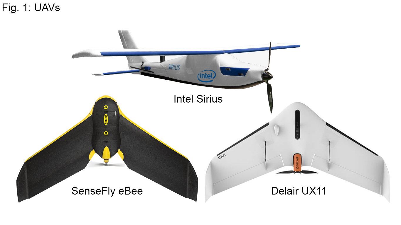
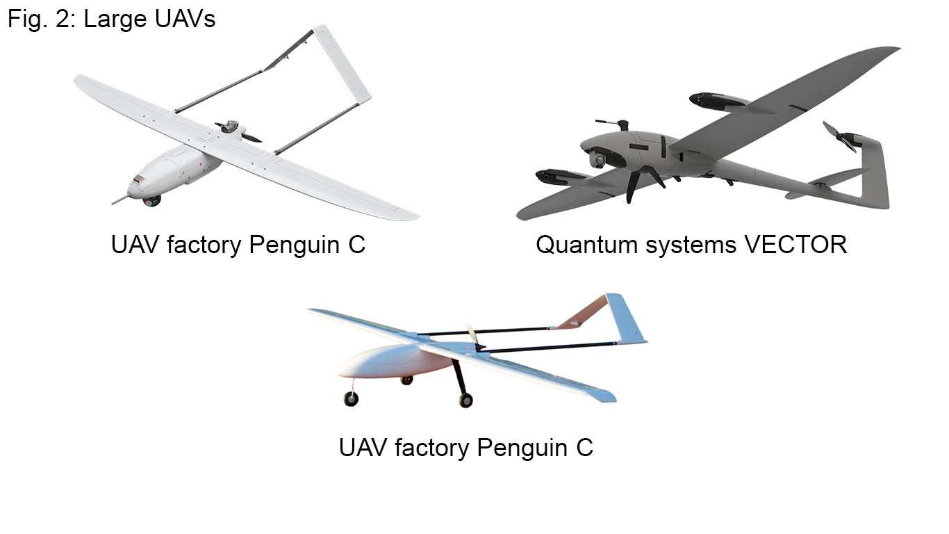
There are two main UAV types - multicopters and fixed wings.
Multicopters, also known as multirotors or drones, are mass-produced and relatively cheap. It is possible to buy a good drone for the price of this plane. They are useful for small short-range missions and I think stable footage (thanks to the gimbals) is one of the best features they offer. When one needs an out of the box UAV that doesn’t require any previous experience, tinkering or extensive footage post-processing, one can’t find a more convenient way to fly. Despite all the positives every manufacturer stresses in commercials, you receive a product that can’t effectively perform all tasks. Flight efficiency of multirotors has been steadily improving, but is still terrible when compared with fixed wings. Likewise, multicopters can hover which is a nice feature, however, the maximum flight distances multicopters are capable of are shockingly smaller than those of fixed wings.
On the contrary, as mentioned above, fixed wings are much more expensive. They are efficient and good for long-range, long endurance applications. Thankfully, there is a growing market segment with affordable EPP (extruded polypropylene) planes that lie somewhere between hobby RC models and professional UAVs, filling the performance gap between big UAVs and multicopters. They can be purchased for a reasonable price and some of them even come preassembled. But they are still a bit pricey for the majority of applications.
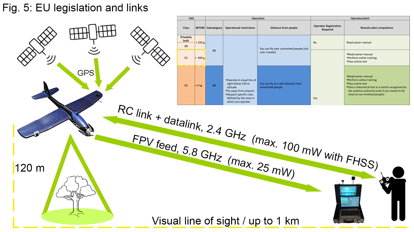
European legislation is fairly strict, not allowing flights out of sight or beyond one kilometer and confined to a maximum height of 120 meters. Similar restrictions also exist in other countries around the world, ensuring safe UAV operation. An operational area which complies with these rules can be easily calculated with a simple formula S=πr². The area is approximately 3.14 kilometers squared (or roughly 1.2 square miles), which doesn't seem that much at a first glance. But you need a plane with a good flight time to cover the area with a circumference more than six kilometers (3.7 miles) long. These regulations currently don't permit many possible use cases of UAVs, like delivering small packages, dropping objects and even fully autonomous flight.
Mapping and reconnaissance were the most plausible use cases for me, which is why I needed a plane with flight times of over one hour. Compactness and good maneuverability were other key features besides the flight time.
Here are the features I proposed to suit the use cases:
- Wingspan - less than 1 meter (3.3 ft)
- Weight - under 1 kilogram (2 lbs)
- Material - EPP (extruded polypropylene)
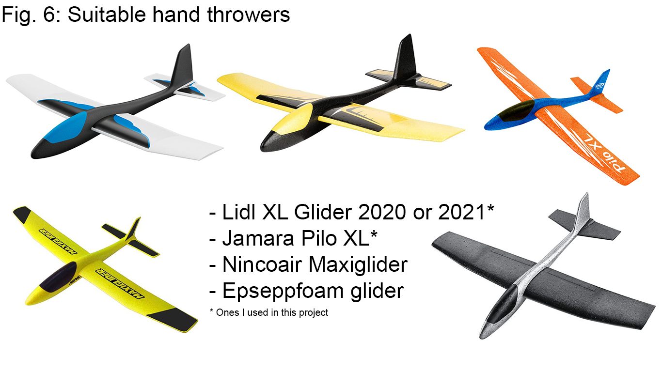
As I wrote, one can buy preassembled EPP models, however, I came up with another solution. There are small EPP hand throwers available for kids which can be purchased for much cheaper. They are produced with wingspans ranging from 38 cm up to 1 meter. I got my hands on ‘LIDL XL gliders’ with a wingspan of 89 centimeters, which can be purchased in the widespread LIDL supermarkets all over Europe. This is a common size that is available in most parts of the world. They fly pretty well and many RC hobbyists buy them to convert them into remotely controlled gliders and park flyers. Some even use them for an FPV flying. But I tried to push their capabilities even further.
One might wonder, why don't we just build a plane from scratch? EPP has some unique features like low density and impact resistance but it`s molding process can not be easily reproduced at home. For that reason, buying the plane is a better solution.
I got my EPP gliders for 10€ and 15€ respectively, which is much cheaper than regular RC hobby models which can cost more than 70€ without any electronics. One can find a few cheaper models on sites like Aliexpress, selling for less than 50€, but they can be trickier to modify for long endurance missions.
Another big design choice is the type of the airplane. I strongly recommend picking a normal 4 channel plane and not a flying wing. Flying wings can be a bit more efficient, however, they have a higher flying speed, are less maneuverable and are prone to stalling. I own three flying wings, but I don't fly with them that often. From my experience a classic airplane is much better suited for this type of close-range application.
Design
You may have noticed that I have made multiple prototypes before I reached the final design. In spite of that, they have many things in common. Every one of them has a reinforced wing and fuselage. Because of the increased weight of the plane, I also had to structurally support the weakest parts that would have deformed or even failed otherwise. I found out that the thin carbon fiber strip stiffened the wing enough and weighed almost nothing. I used square carbon fiber profiles for reinforcing the fuselage from both sides along its length. These two profiles formed a frame of sorts and allowed me to make large cutouts for the battery and the camera.
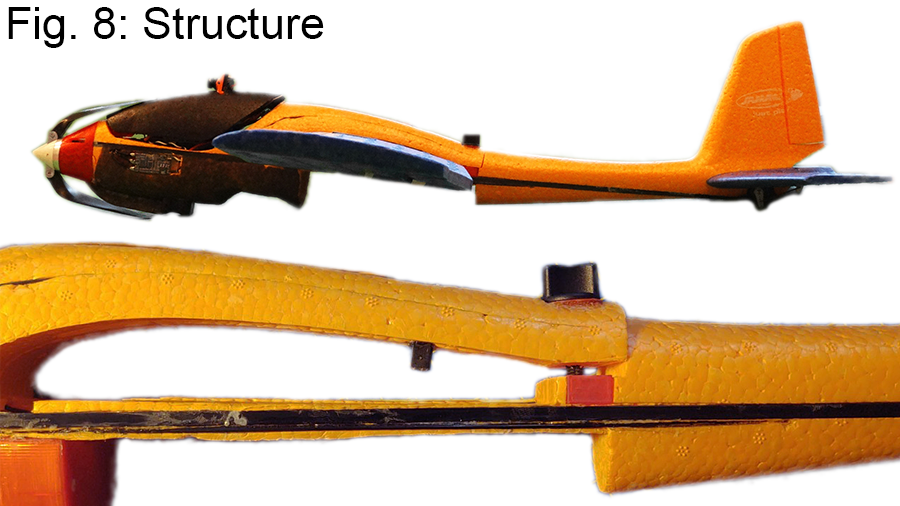
I wanted to have a detachable wing to make the plane extra compact. I settled on a simple one screw mechanism which is attached to the main carbon fiber frame. There is an 8-pin connector for electrical connection between the flight controller and components on the wing.
The canopy is held in place with a simple locking mechanism. In the front is a 3D printed hinge and in the back a special “Dual lock” tape. It allows one to lift off the canopy from the back and as well clip it off entirely when one needs to.
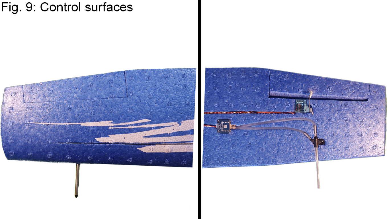
Control surfaces and their edges were cut out using a sharp razor blade. Then I glued them back using foam glue which made a very strong yet flexible bond. This way, the hinges are much more durable than simple tape ones.
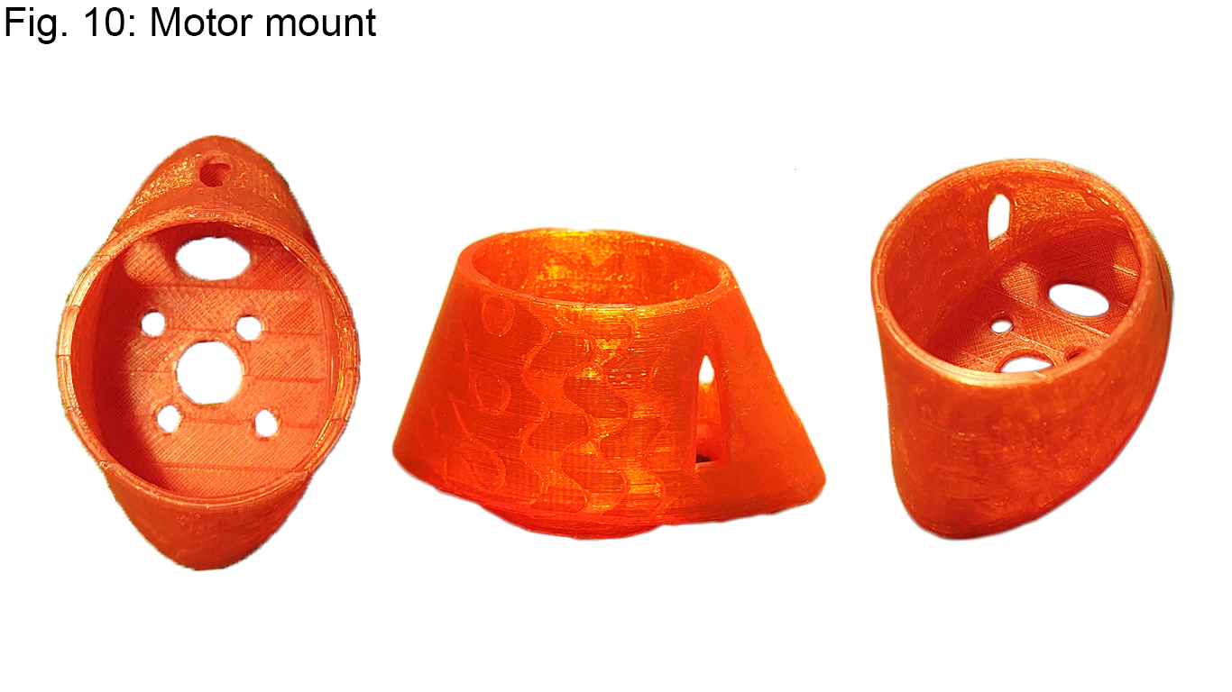
The motor mount is used to attach the motor to the fuselage and also protects the motor from dirt. I made this attachment semi-permanent to save weight. The motor can still be cleaned from the front and can even be removed when needed by carefully cutting the adhesive. Nevertheless, I think there will be no need to swap the motor during the UAV’s service life.
On the bottom of the plane there is a landing sledge. Its main purpose is to protect the FPV antenna, propeller and camera.
Components
Motor
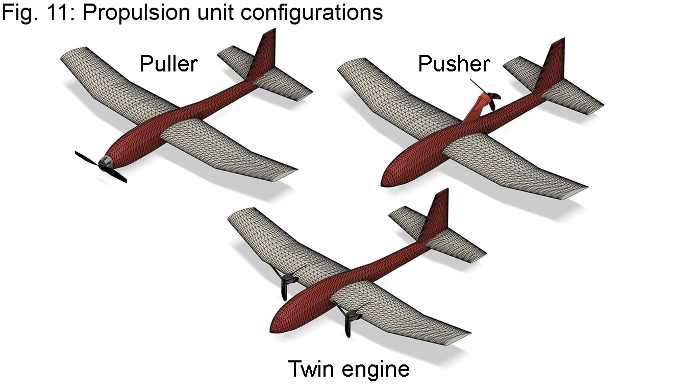
Firstly, I was looking for the best motor placement on the plane and then for the most efficient combination of the motor and propeller with high enough power required for the flight. I considered three propulsion unit configurations: puller, pusher, and twin engine. I selected the puller for having the most advantages. This configuration allows for the easiest and the lightest motor placement and can accomodate the biggest propellers.
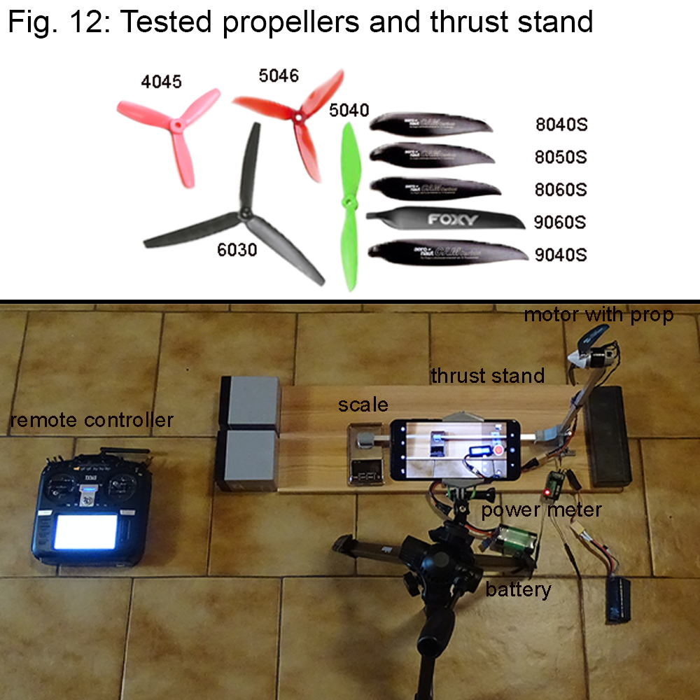
Then I got my hands on as many motors as I could and statically tested them with different propellers to find the best combination. As a rule of thumb, a bigger propeller and a slower speed of the motor gives you a more efficient propulsion unit. The science behind it is very simple - there are smaller losses when you accelerate a big volume of air slowly with a large propeller.
Another advice is that the motor should not weigh more than 15% of the total weight of the plane. A heavier motor will practically serve no meaningful purpose and will effectively shorten flight times by adding extra weight to the plane.
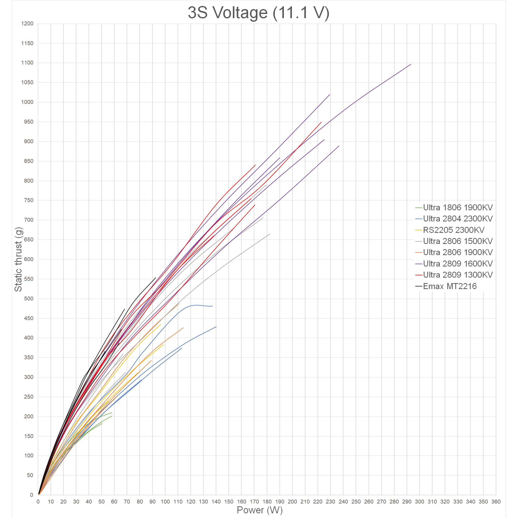 | 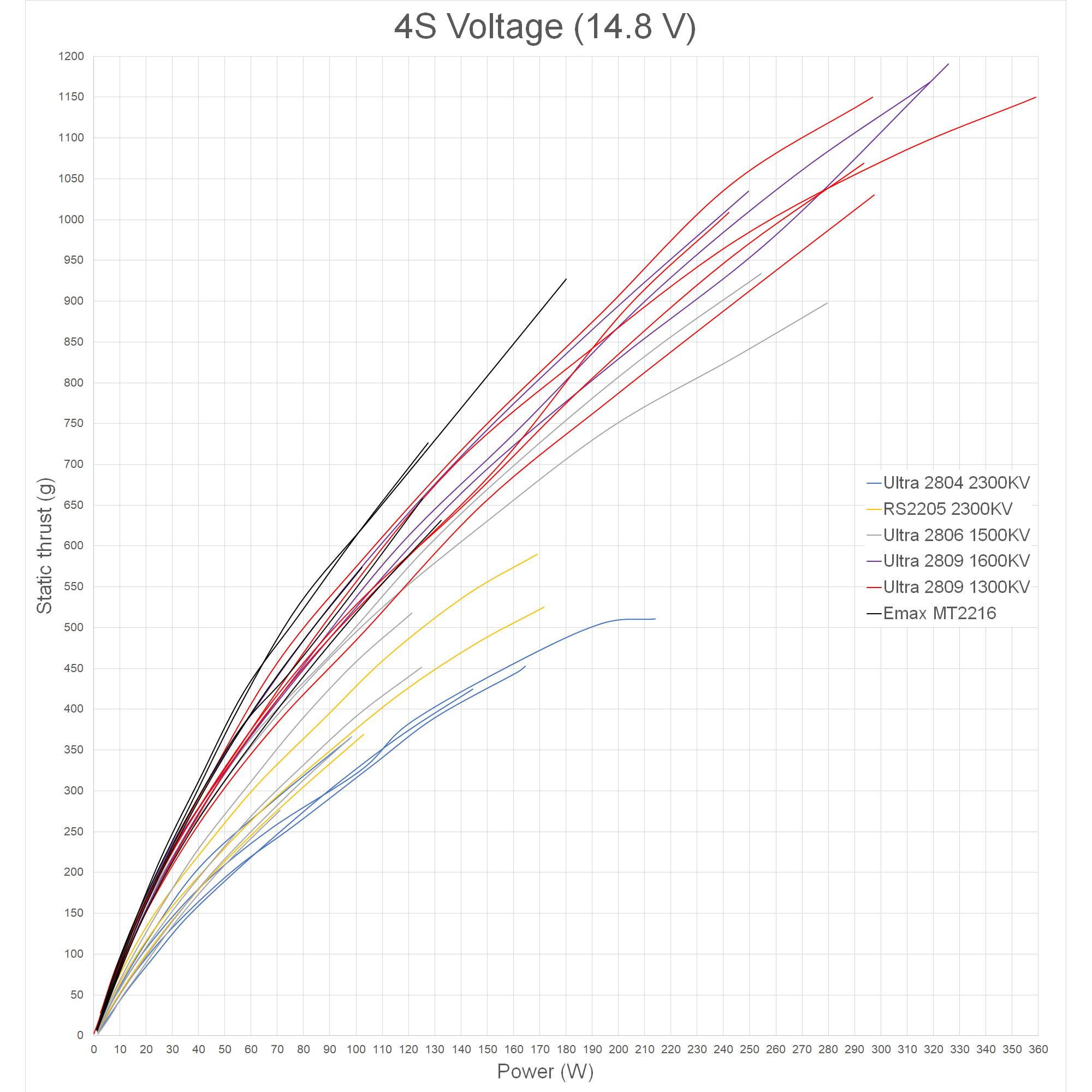 |
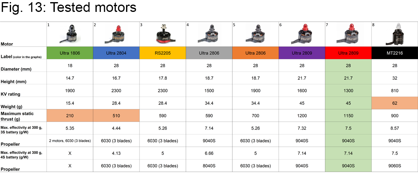
The results from my tests were not that surprising. I found a big and foldable propeller (9x4 in) paired together with a 1300KV 2809 motor was the best choice, taking weight into account. Differences between the best motor and prop combinations were fairly small, but in comparison with the least suitable pairs the differences were much more significant - up to 50%.
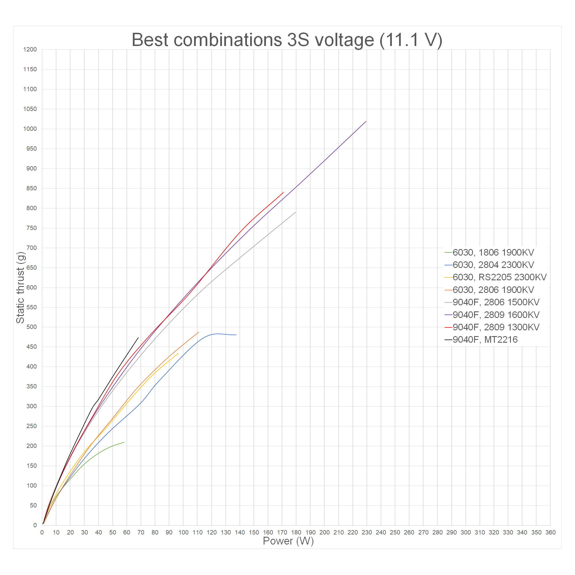 | 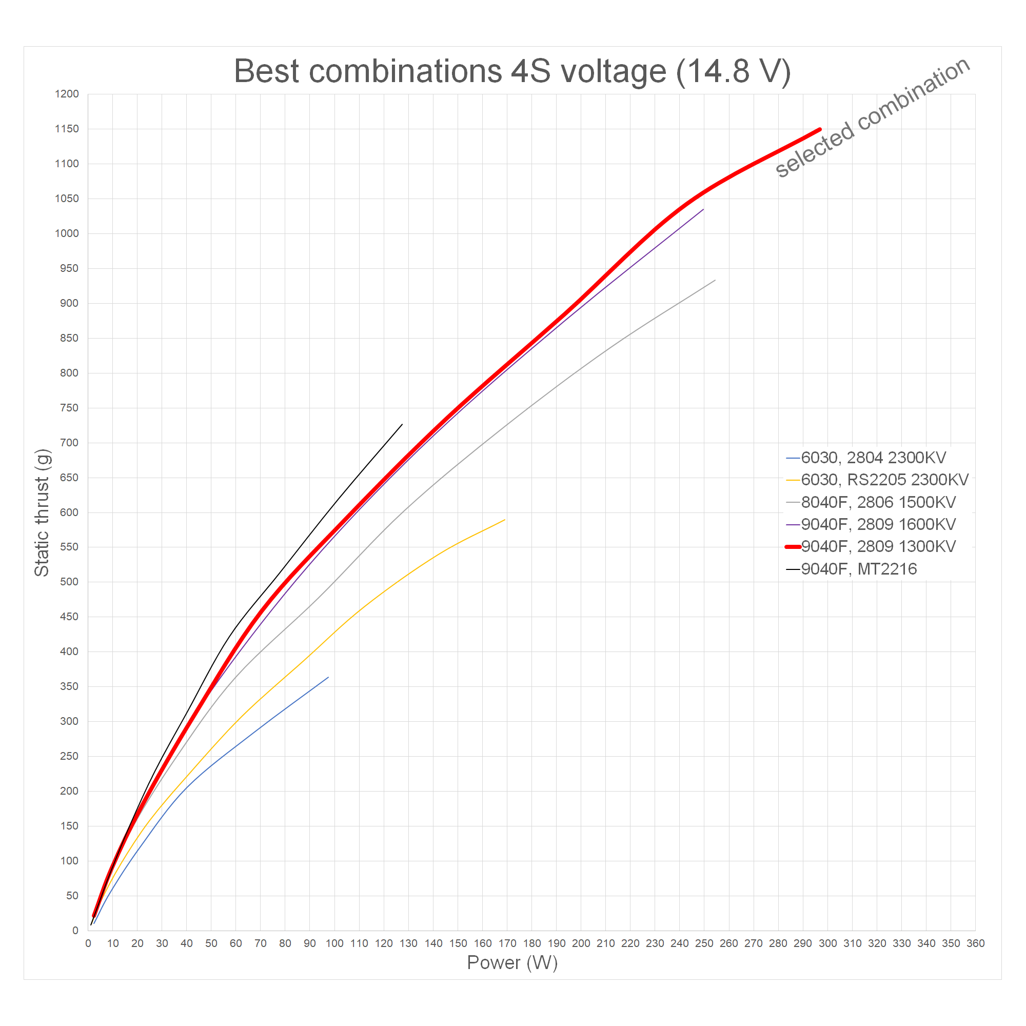 |
From all the tests I concluded that the most appropriate motor would weigh between 40-50 grams and have a KV rating of around 1000-1500KV. Combined with a 9 inch foldable prop with 4 inch pitch, this makes a good performing and very efficient propulsion system for my purpose.
Battery
There are two battery types which can be used for this model. LiPo batteries are the more popular type. They have an acceptable energy density and are able to deliver high currents. LiIon batteries, on the other hand, have much lower current discharge characteristics. However, they can be as much as two times denser when comparing energy density.
I flew the planes with both battery types. Planes power requirements are very low, pulling only about 2-3 A when flying, so one can take the full advantage and use solely LiIon battery cells. But it's completely acceptable to also use a LiPo battery you may have lying around, assuming it will fit.
When looking for LiIon cells, it's best practice to look for the ones with highest discharge currents. They will perform a lot better at the ends of flights when they will be almost empty. Other cells will sag (sudden voltage and performance drop) a lot sooner, certainly putting the plane at risk of crashing.
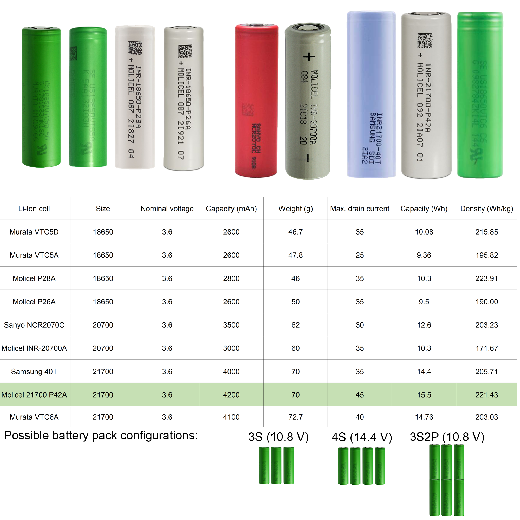 | 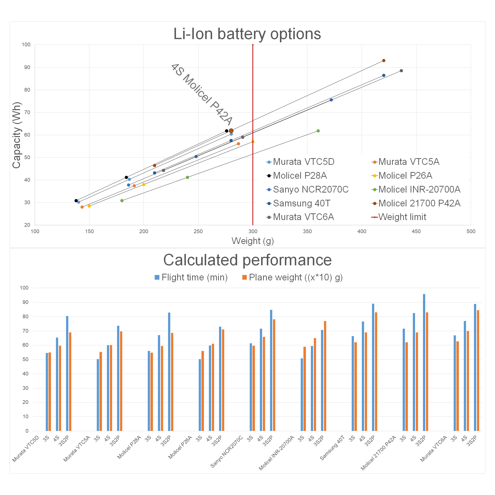 |
I did my research, looking for the best cells I could get my hands on. I wanted to make a four-cell in series pack, and as I already had one plane built, I calculated the expected performance with a few simple equations. With the help of them I was able to estimate the flytime, average speed and the flight distance for every battery I could possibly build from these cells. In the end I chose Molicels INR21700 P42A cells and based on my experience, I can confirm their excellent performance. Their energy density at 220Wh/kg is almost double the density of normal LiPo cells(120Wh/kg), yet they can still deliver enough current for a steep climb.
Flight controller
The flight controller and many other components listed below are not that crucial for flight efficiency. You may pick any other component you have at home. When looking for a new one, you will get what you pay for. Just be sure to check the compatibility and features you need. If you want to use this UAV with the Ardupilot software, make sure to check if your flight controller is supported here: https://ardupilot.org/plane/docs/common-autopilots.html
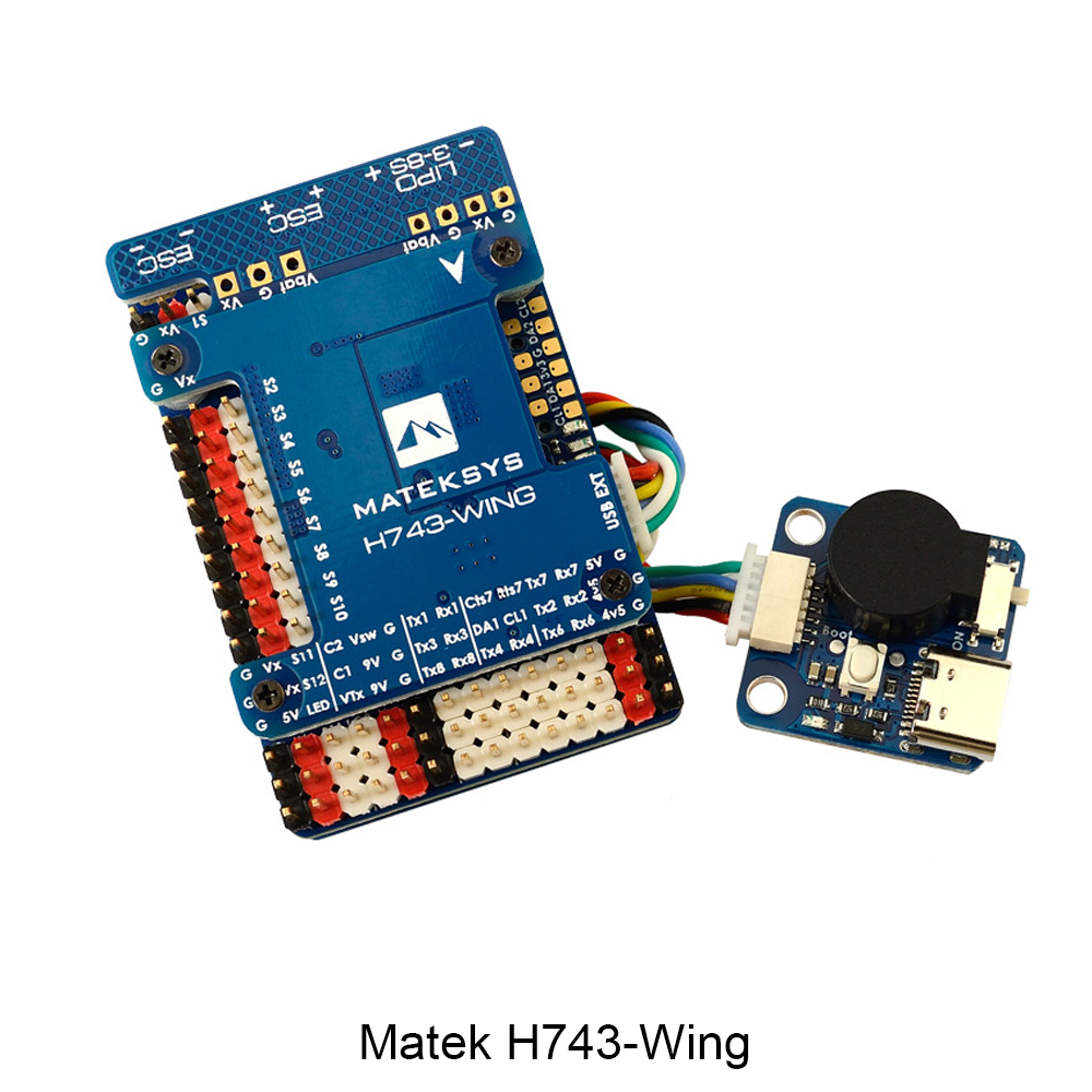 | 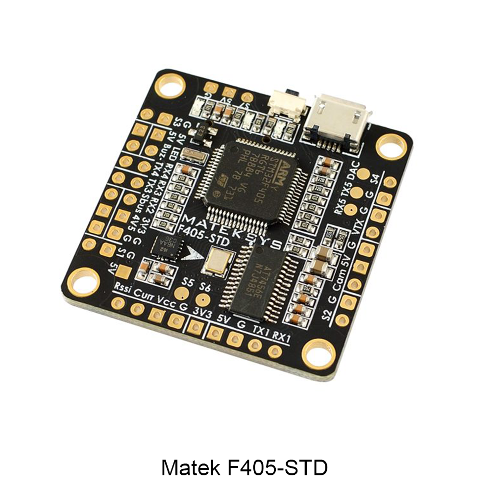 |
I used a baseline Mateks F405-STD in the second prototype and have now moved on to a more expensive Matek H743-Wing. It can measure current, has better voltage regulators and almost endless possibilities regarding connectivity. If on a tight budget, I would definitely save some money and go with a cheaper one. However, be careful to avoid buying any cheap clones! I've used some of them, but they proved to be very unreliable and unusable.
RC Link
There is a wide range of hobby transmitters. If you want to have a relatively cheap yet advanced radio, then look for a radio with OpenTX open-source firmware. Otherwise, if you have a really tight budget, the simplest and cheapest radios like Flysky fs-i6 will do the job just fine.
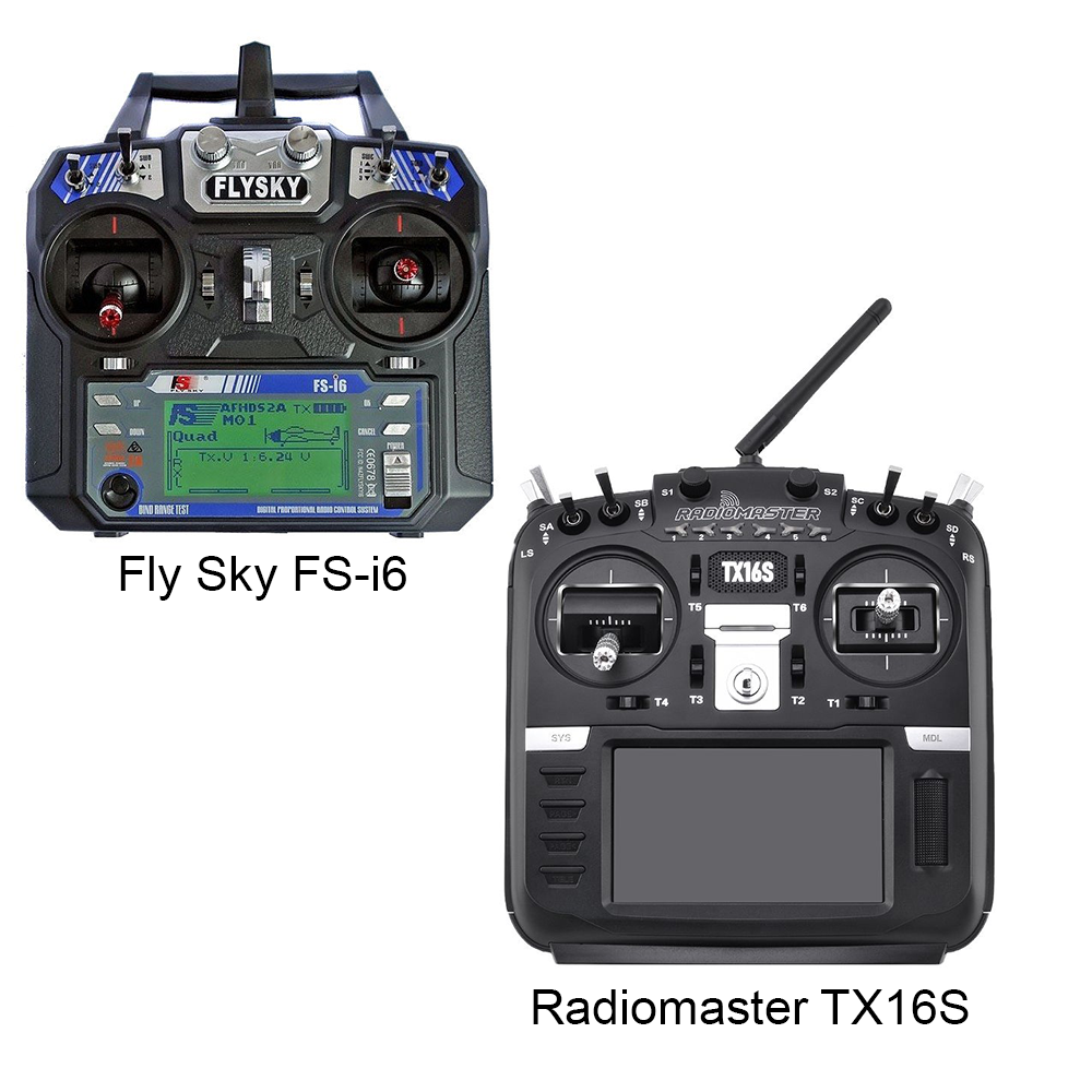 | 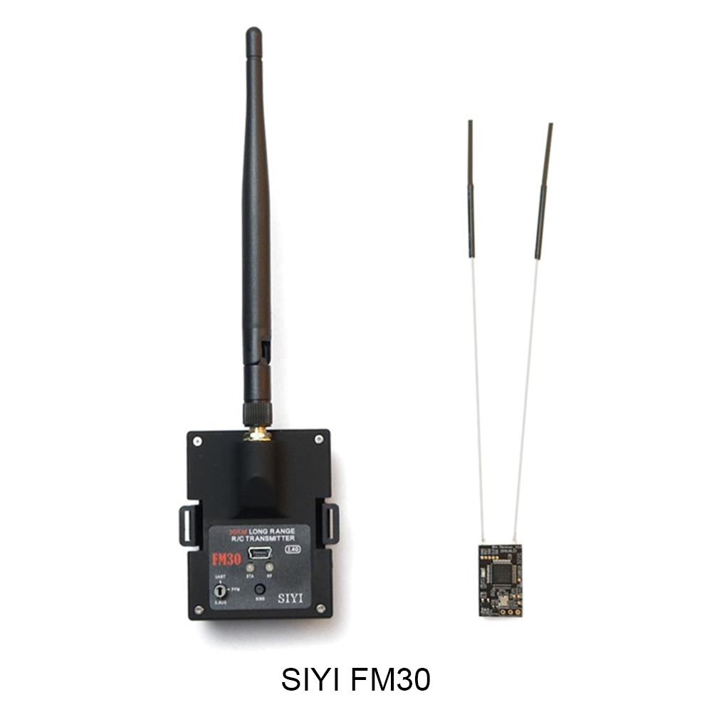 |
I use my Radiomaster TX16 radio with an optional SIYI FM30 long range module. This module has a range of dozens of kilometers and it also works as a datalink, streaming live data to a laptop, as if the plane was connected via a USB cable. The telemetry data from this datalink is processed and the exact location of the plane can be shown on the map together with other critical flight data, such as speed, height, energy consumption and much more.
GPS module
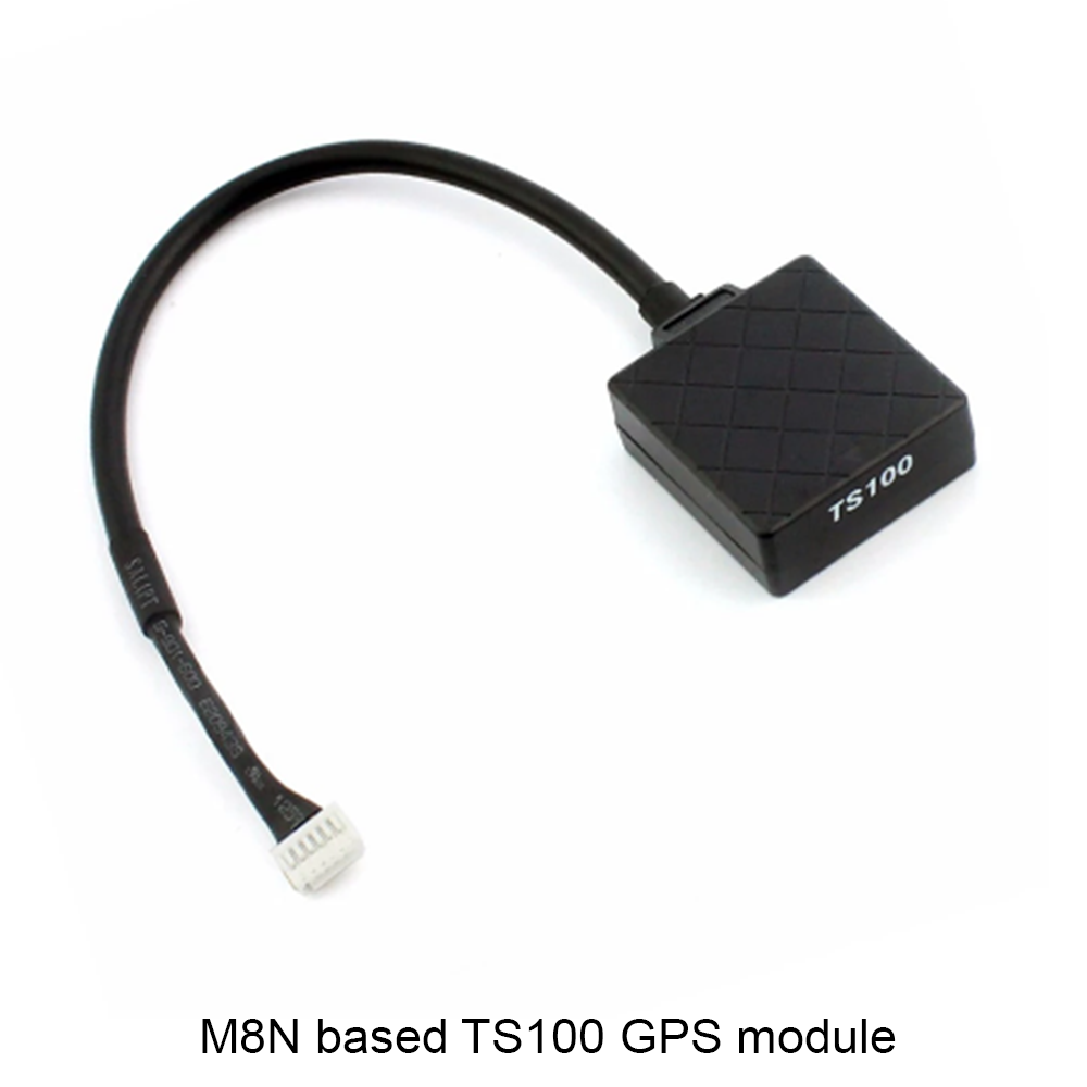
You can use almost every hobby grade GPS module with a UART interface. Often there is a compass included in the same module. Nevertheless, you won't need it in a plane. I used reliable and cheap modules with the M8N chip. To achieve the best flight performance you can reasonably save weight on these components.
Airspeed sensor![]()
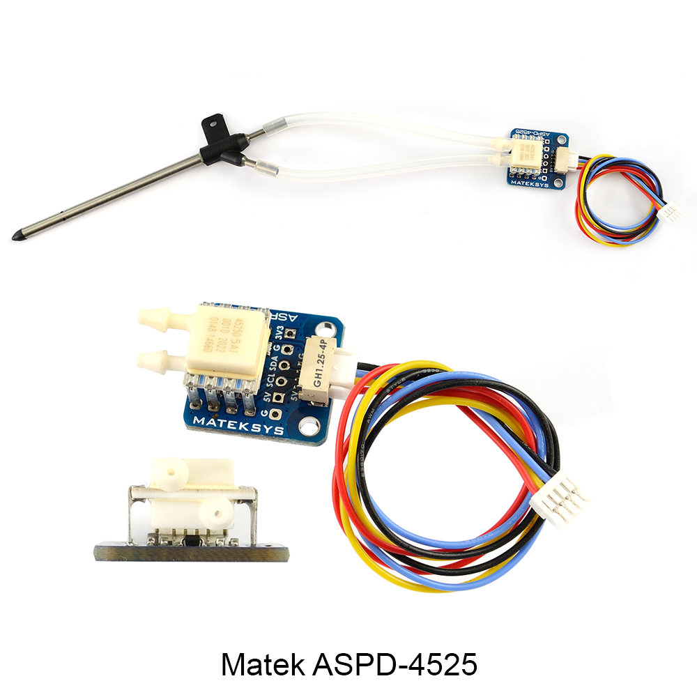
This sensor is a bit pricier than others. It's best to have one if you want to use features like autonomous missions and landings. By measuring the true airspeed, the plane is able to maintain optimal flight speed and prevent stalls. There is a great difference between ground speed (computed by GPS) and airspeed if the plane flies in windy conditions. Without this sensor the autopilot will fly the plane faster and less efficiently. The airspeed sensor has to be placed in an uninterrupted airstream and not behind the propeller, as this would falsely indicate the airspeed even on the ground.
ESC
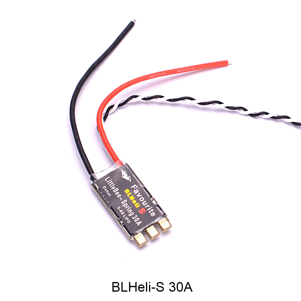
An electronic speed controller drives the brushless motor by passing current into its coils in a special sequence. An ideal ECS for this plane needs to handle voltage from a four cell battery and currents up to 20 Amps. There are ESCs capable of bidirectional motor control and this can be used in steep landings when the plane can actively brake by reversing the thrust direction.
Servos
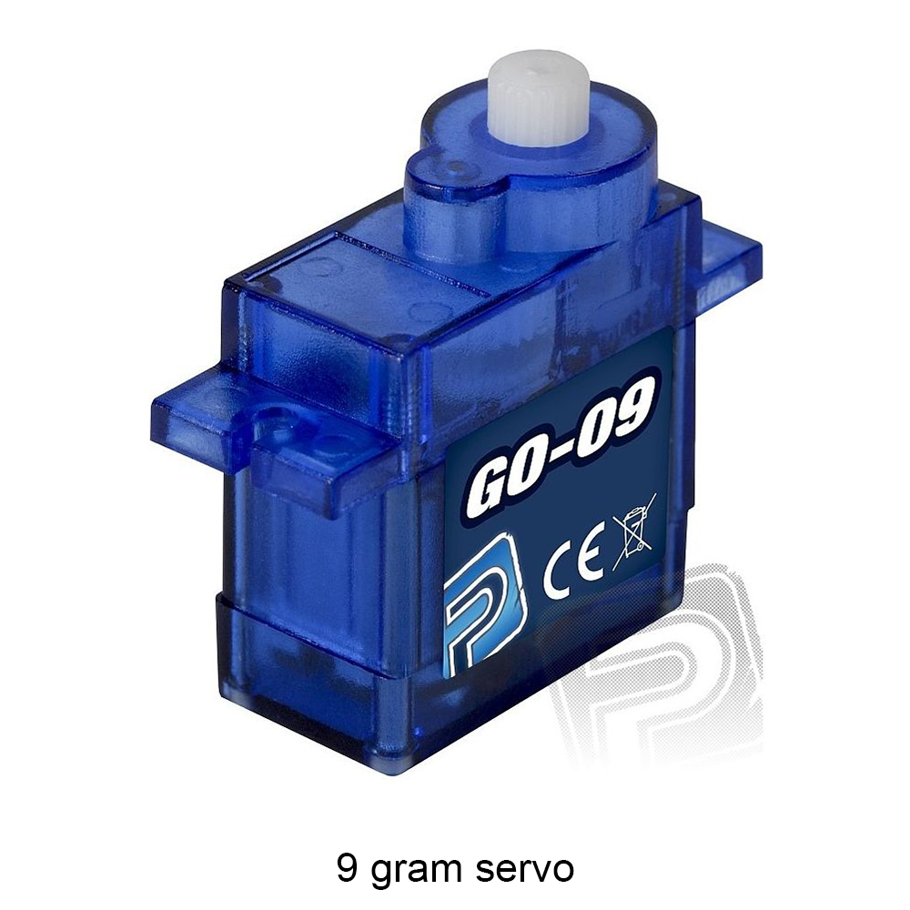 | 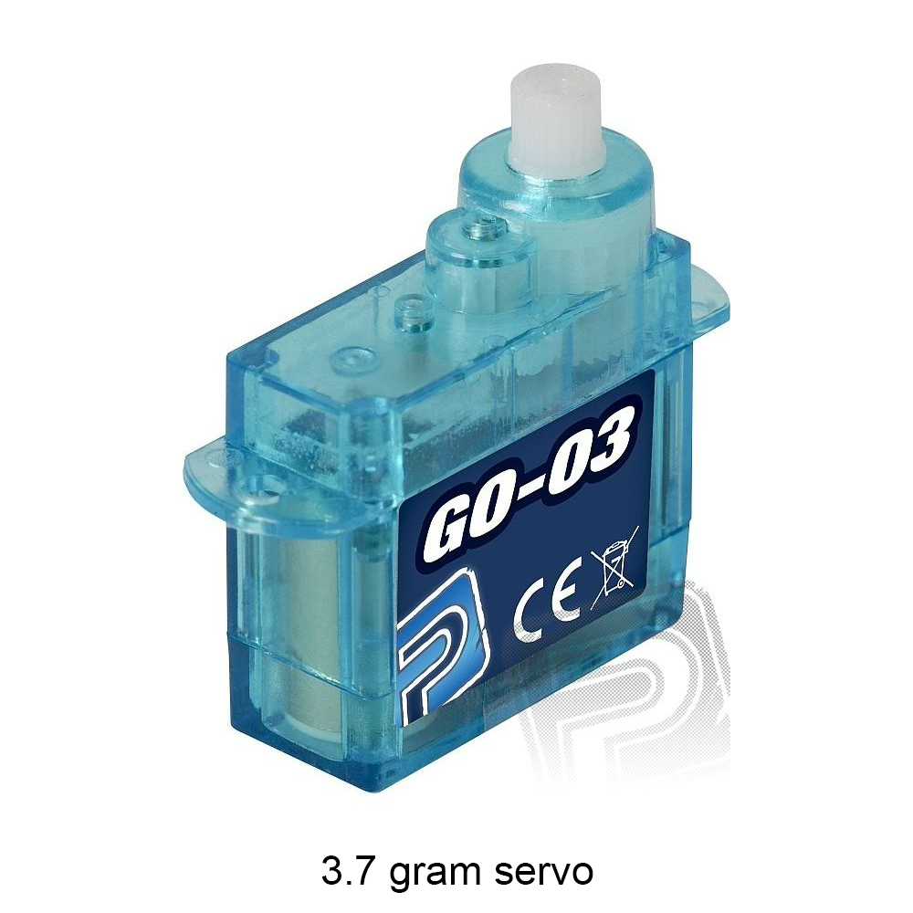 |
Servos are small rotary actuators used for moving control surfaces. Manufactured in many different sizes, you just have to pick ones with an appropriate size and weight. I used a popular 9 gram servo for the elevator and 3.7 gram servos for other control surfaces to save some weight.
FPV camera
Converts the image to an analog signal. There are two major types of cameras based on the sensor they use. CCD cameras have a global shutter, which means they make one frame by instantly exposing the whole sensor at once. CMOS cameras are generally cheaper and use a rolling shutter making the frames continuously from top to bottom, which distorts the fast moving objects in the frame. That's why I used a Runcam Micro Swift 3 camera with CCD sensor as I mounted the FPV camera behind the propeller.
VTX
A video transmitter broadcasts video from the FPV camera through the antenna as an analog signal. There are new digital systems, but these analog systems are much cheaper, accessible and have acceptable performance. Be sure to check your local regulations for a maximum power output on the 5.8GHz frequency. This transmission system can help the operator to safely navigate the plane by providing a real-time video feed. By placing a flight controller between the FPV camera and transmitter, one can also inject some crucial telemetry data into the feed. Together with the data link, this adds a layer of redundancy.
FPV Antenna
It's important to have a compact omnidirectional antenna on the plane. Both antennas (on the plane and on the ground) need to have the same polarization. The most common one is right hand circular polarization. A mismatch will greatly affect the performance of the transmission.
HD camera
The main recording device on the plane is a GoPro Hero 8 camera. Originally, I used a Runcam 5 camera on the first and second prototype. I disassembled it and placed it on the wing into a special tilt adjustable mount. Therefore it was capable of recording from the “pilot's” perspective and also top down. I considered this unique mounting position to be a viable option and developed it for a long time.
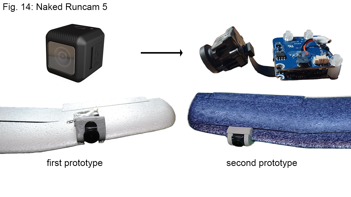
The first prototype suffered from a nonsymmetrical vertical placement of the sensor module on the wing - it was placed higher to protect the lens during landing. This created turbulent vortices on the left side of the wing, increased stall speed, reduced maneuverability and made the plane prone to tip stall.
With the second prototype, I placed the camera lower and on the opposite side of the wing to counteract propeller torque (which I measured beforehand). The flight characteristics improved drastically, but they were not perfect yet. I then rethought the plane applications and reached the conclusion that there is no valid reason to capture the scenery from the pilot's view. If one wanted to shoot cinematic clips, the multirotor would be a much better option by providing gimbal-stabilized footage. The only purpose I could find was to record the flights and then view them at home in high resolution from the “pilot's seat”. Therefore, I put this concept aside and focused on the camera placement in the fuselage.
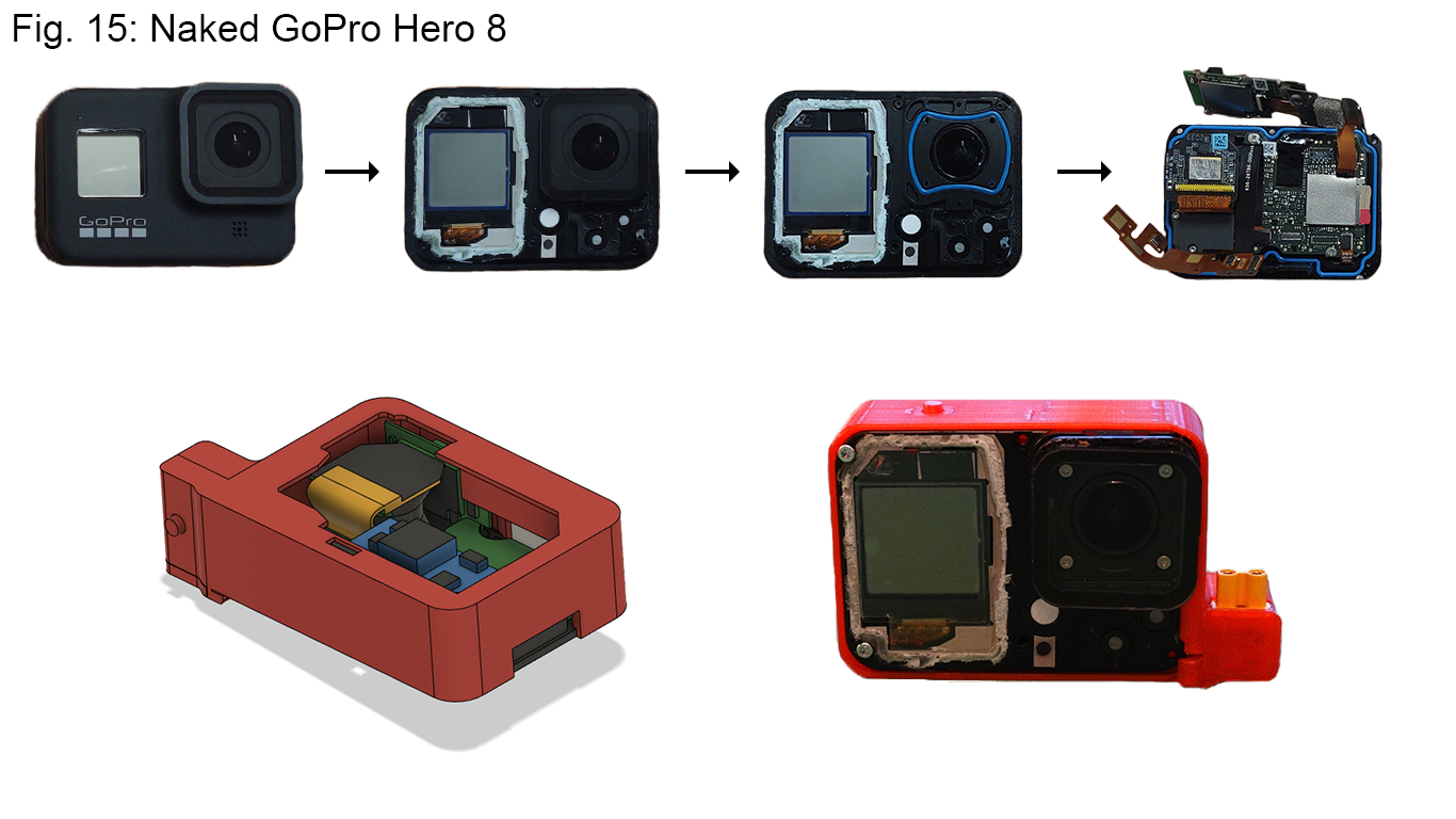
With the help of my school I got my hands on a GoPro Hero 8 camera. It is capable of shooting high resolution videos and photos, and is small in size. GoPro cameras are very popular with FPV drone enthusiasts. People from this community found a solution to the one drawback of these cameras, which is their weight. By disassembling the camera one can remove as much as 90% of the original weight (126 g → 14.8 g) and still have a functioning camera. This technique, however, completely removes any durability the GoPro cameras are famous for.
I haven't seen anyone make a so-called “naked” GoPro camera for a plane application. Nevertheless, I wanted to do it for three reasons. With expected flight times of over one hour, the GoPro would have to be fully charged to record the entire flight. It would be almost impossible to achieve such a long flight time with a camera weighing up to 20% of the entire plane mass. The third point for this idea was the presence of a safe mounting place inside of the fuselage.
I disassembled the camera and designed a special case for it. By doing so, I reduced the weight from 126 g to 58 g. Equipped with a standard XT30 connector, the camera is fully functional and with a voltage regulator inside the case, it can be used with any battery for other applications. The biggest drawback of this approach is the loss of water resistance. Compared to other naked GoPros out there, I kept the protective glass over the lens and preserved the main metal frame on which all circuit boards are securely mounted. Thereby, there is a smaller risk of damaging the camera during a crash. The camera slides into the mount from the side, plugging into the power connector, and the camera is ready for flight.
Theory of flight
Flight performance calculations can be very complex. When designing a real plane, there can be groups of people working on design optimizations, trying to achieve the best performance. At the moment, I don't have the knowledge to be confident enough to work with advanced methods like CFD and present them here. Although, I’ve tried it and maybe I will post my findings later.
Despite that, one can use much simpler calculations to achieve the same thing, roughly predicting the plane's behavior. With my simple approach, I’m able to predict the changes of three crucial flight parameters: the flight time, speed and range, when changing the weight, battery capacity and auxiliary power draw of the plane.
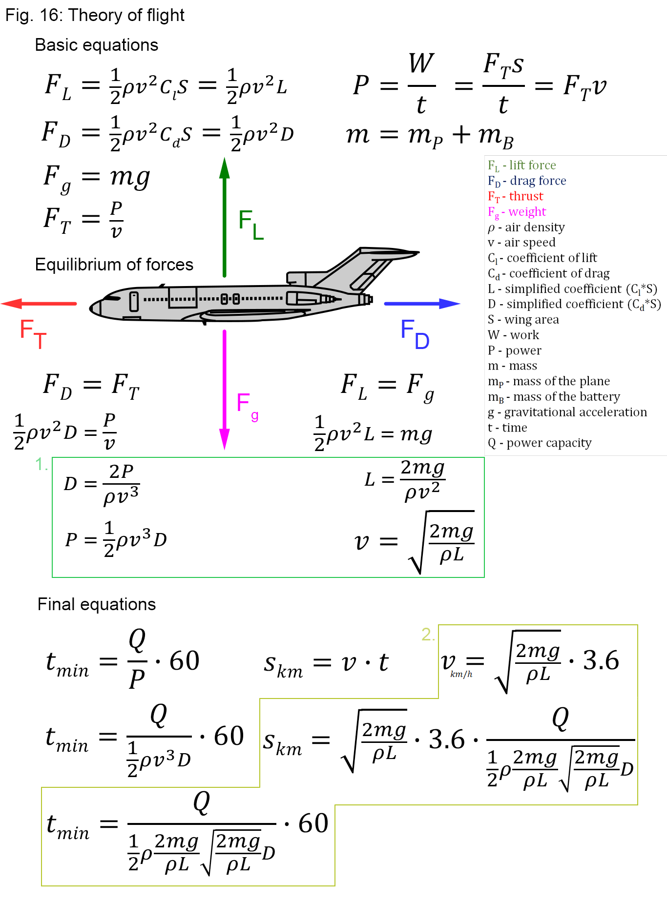
Every calculation I do is based on the basic formulas shown in the picture. There are two aerodynamics formulas for calculating lift and the drag force, one showing the relation between power and force, and the last one is for calculating weight.
When we look at a steady flight at a constant height, we can consider it a linear motion with a constant velocity. The four forces that I mentioned above are then in equilibrium. The lift force is the same as the weight and the thrust is the same as the drag. By comparing these, we can derive formulas for simplified lift and drag coefficients, the power required for this steady flight and the speed at which the plane is traveling. The final step is to construct formulas for the flight time, range and average speed.
These final equations can be used to calculate the performance of the modified plane by comparing it to data from previous flights. For example, I flew the plane with a small battery for 20 minutes until the battery was almost empty. After the flight, I charged the battery and wrote down the energy that was charged back (equal to the energy drained during the flight) and calculated the average power draw from it. From the data logs on the flight controller, I got the average airspeed from that flight and the duration of the flight. I then also measured the weight of the plane with a scale. Having all the necessary data, I was able to calculate the two important coefficients. After that, I was able to substitute them in the final equations and calculate the performance of the plane with the changed weight, battery capacity or power draw.
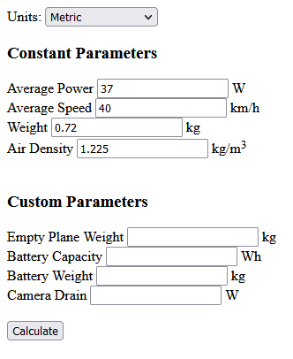
With help from a friend, I made this simple calculator you can use to predict the performance of your plane when replicating this project or any other plane you may have at home. First you have to determine the flight time and average speed. Next, you have to calculate the average power draw from the flight time and the energy drained from the battery. It’s simple, just charge the battery after the flight and multiply the amps charged to the battery (miliamps/1000) with a nominal voltage of the battery (e.g. 14.8 V). You will get a number of Wh used up during that flight. Now you have to divide it by the flight time in hours and you have an average power consumption in watts.
You can feed this data into the calculator together with the new parameters. Then just click the button “Calculate” and you will have your results.
Tips:
- Bear in mind that the average power you calculate includes the power draw of all components, thus be aware that changing any of them will affect the calculation.
- The average power of the test flight is heavily influenced by its flight time. A short flight time results in a significantly higher average power draw, due to flight stages like takeoff and ground checks taking up a higher proportion of the overall flight time and consumed energy.
- Fill in the average airspeed if you have an airspeed sensor on the plane (ground speed can differ due to wind).
- Always compare identical planes with this calculator. The lift and drag coefficients are unique for every plane (even for each of my prototypes), therefore using the wrong ones can give you misleading results.
- You can directly insert the coefficients, if you calculated them before. Here are the sample values for my prototypes: 1: L = 0.061262, D = 0.041327
2: L = 0.075309, D = 0.040098
3: L = 0.102061, D = 0.048587
- This calculator works by using coefficients as constants. In reality, however, they change a lot with the angle of attack. Nevertheless, from my experience they can be used in this way when comparing average values from the whole flight.
- When you want to calculate a more accurate maximum flight time of a new plane configuration, always enter at most 80% of the new battery capacity. You can never safely discharge the battery completely and there will always be around 20% of spare capacity that can’t be used at the end of the flight, due to big voltage drops.
- The camera drain input can be used to adjust the power draw of a new plane configuration. For example, if you made the test flight without a camera and you want to account for its power draw in the new configuration.
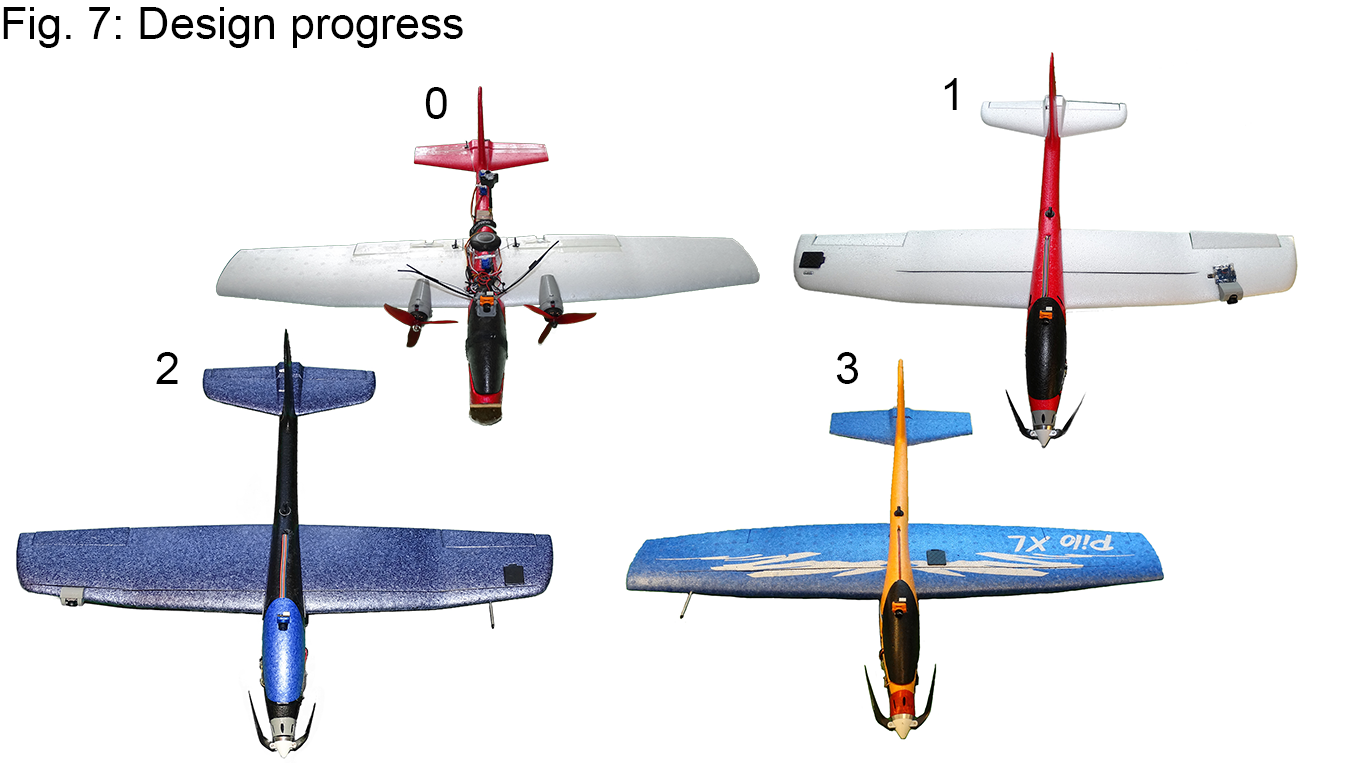
Prototypes
Zeroth Prototype
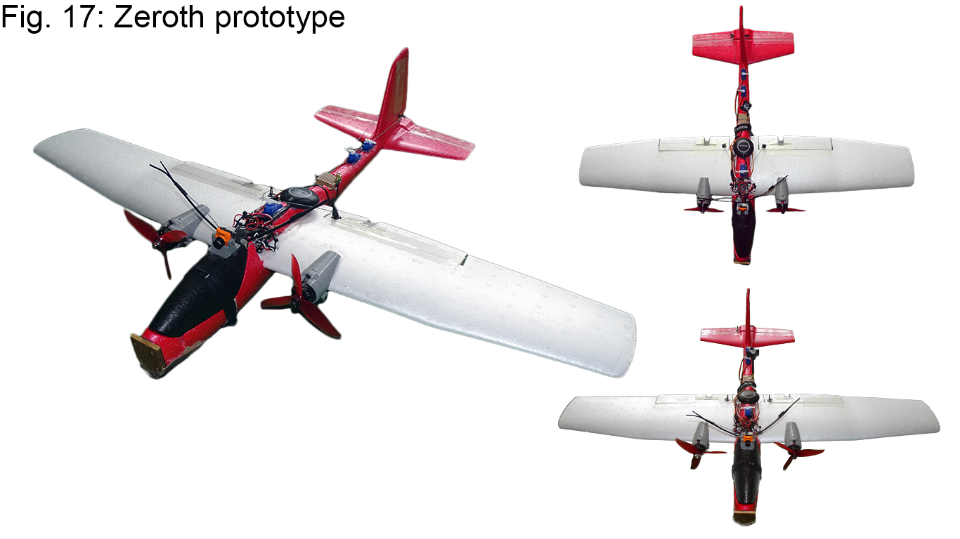
I made this plane two years ago. It was my first EPP glider converted into an RC plane. First, I made a simple puller out of it and I learned how to fly with it. During the next two years I mounted different components on the plane, installed an autopilot and even tried to make a VTOL out of it. Pictured is the last variant with autopilot on the top of the fuselage and two motors mounted on the wing.
The plane had an unnecessarily high thrust-to-weight ratio, at around 2:1, and had some other major flaws. One of them was the bad placement of the ailerons. By being so close to the fuselage, their torque and efficiency were greatly reduced. The components mounted on the top of the fuselage created a lot of drag. The motors and speed controllers added a lot of weight to the wing so it had to be permanently glued to the fuselage. In conclusion, it had many design issues and flew for a maximum of 20 minutes.
This inspired me to start this whole project, to try to make the best performing plane out of these EPP gliders.
First Prototype
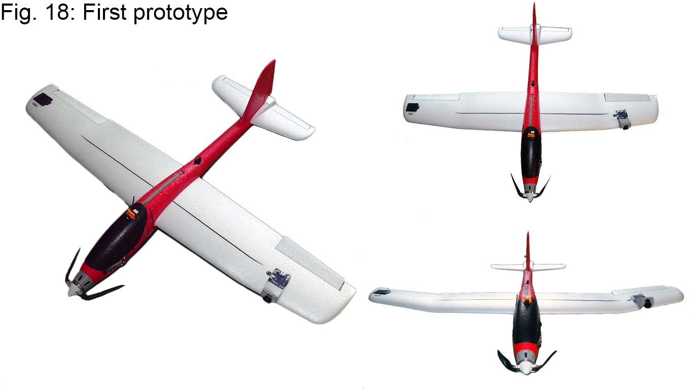
I put a lot of thought into the design of this model before actually building it. Even at first glance, the differences are quite obvious. I focused on the aerodynamics of the aircraft and as a result, the drag was significantly reduced. I also tried to reduce its unloaded weight as much as possible, in the end by more than 15%. The control surfaces were correctly placed and the new efficient propulsion unit was moved to the nose. The average power consumption dropped by as much as 35%, owing to these design improvements.
Second Prototype
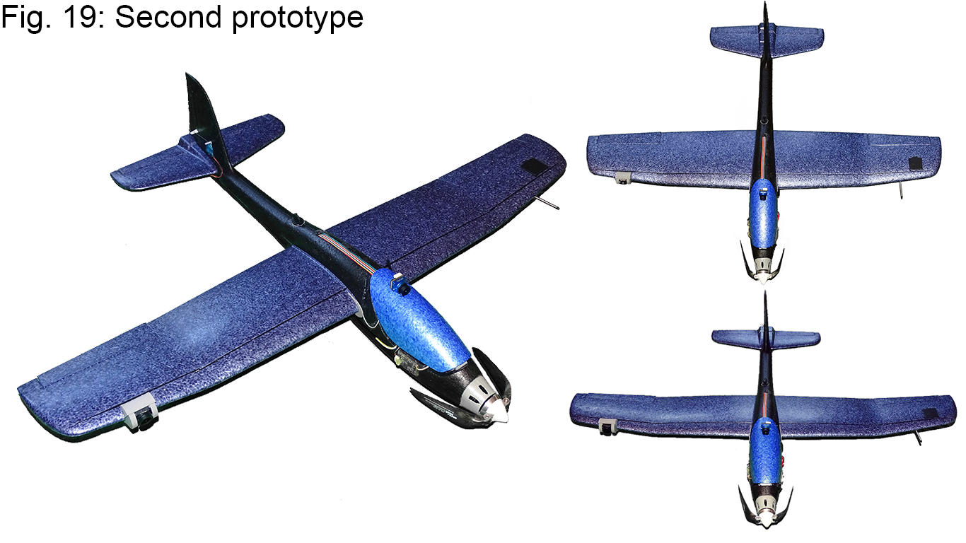
I even tried to fine-tune the less visible details on this prototype. The key difference was the modification of the HD camera mounting, which improved the flow around the wing and the flight characteristics (as mentioned in the “Components” section). Besides that, I replaced the motor (based on my further tests) and optimized the performance of other components on the model.
Third Prototype
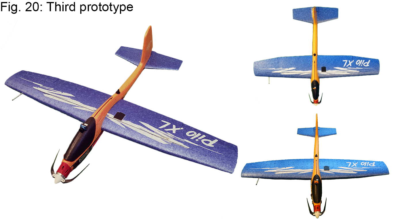
I made this last prototype, as I still wasn’t satisfied with the performance of the plane and completely rethought the camera mounting. At first, I tried to cut the mount for the camera directly into the EPP, but it was quite difficult and time-consuming, therefore I designed a special 3D printable lightweight mount, which can be filled with foam glue for extra rigidity and conveniently glued to the bottom of the fuselage.
The wing was carefully balanced, taking propeller torque into account. I also changed the video transmitter and placed it on the wing together with the FPV antenna. This fixed the issues of the signal being blocked by a rotating propeller in front of the antenna on the first and second prototype.
Final model
I’m quite satisfied with the final model and its performance. You can check its performance here:
The build guide for the battery is out and can be found in the instructions project section. The build guide for the plane itself will come out soon.