 Adam Trizuljak
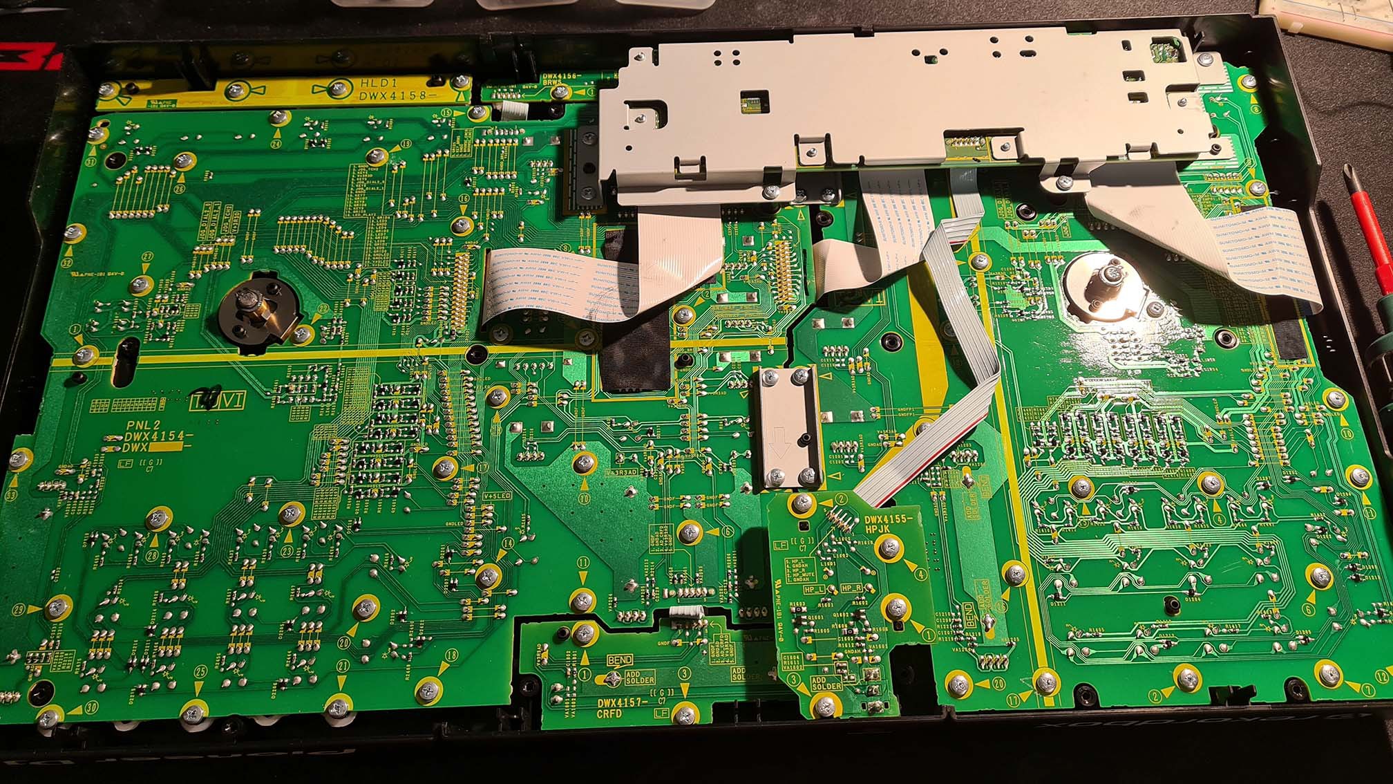
After opening the case we see that the DDJ-400 is split into two main PCBs that host all the potentiometers / faders, buttons and LEDs. The larger PCB (on the left side in the next photo) combines both the right deck and the mixer section and contains many potentiometers and faders, all of which have knobs that have to be removed before the PCB can be pulled out. The left deck PCB is smaller and hosts only one fader and two potentiometers. These boards are connected to the main logic board via flat flex cables.
Since the left deck is much easier to remove, I decided to start with its LEDs as a trial run to see if the intended modification works as desired. Be careful when removing the knobs, you don't want to scratch your controller or even worse, break a potentiometer. Cameron Gray suggests to use a key cap puller, I used two metal spudger tools to symmetrically pry the knobs upwards.
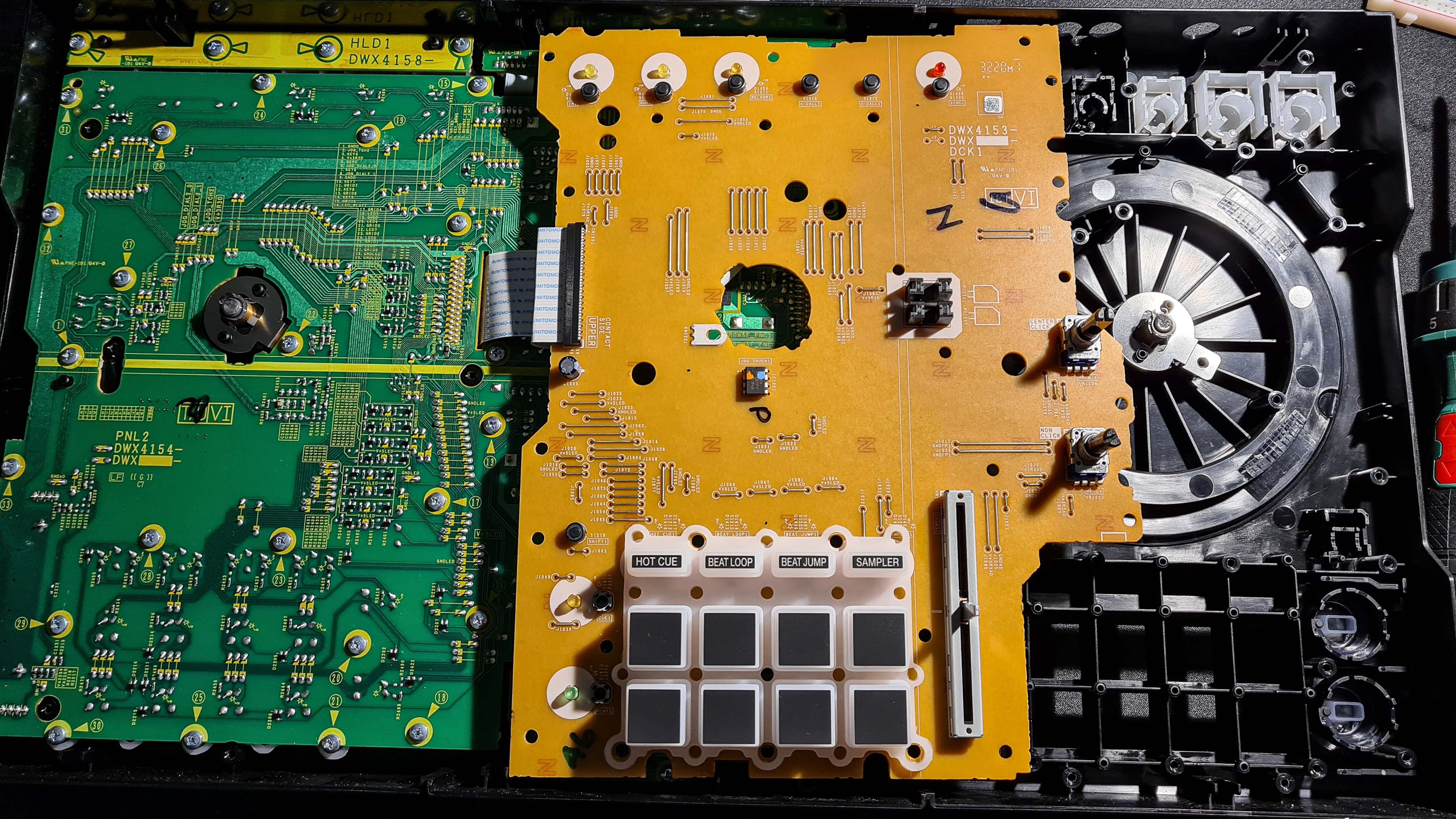
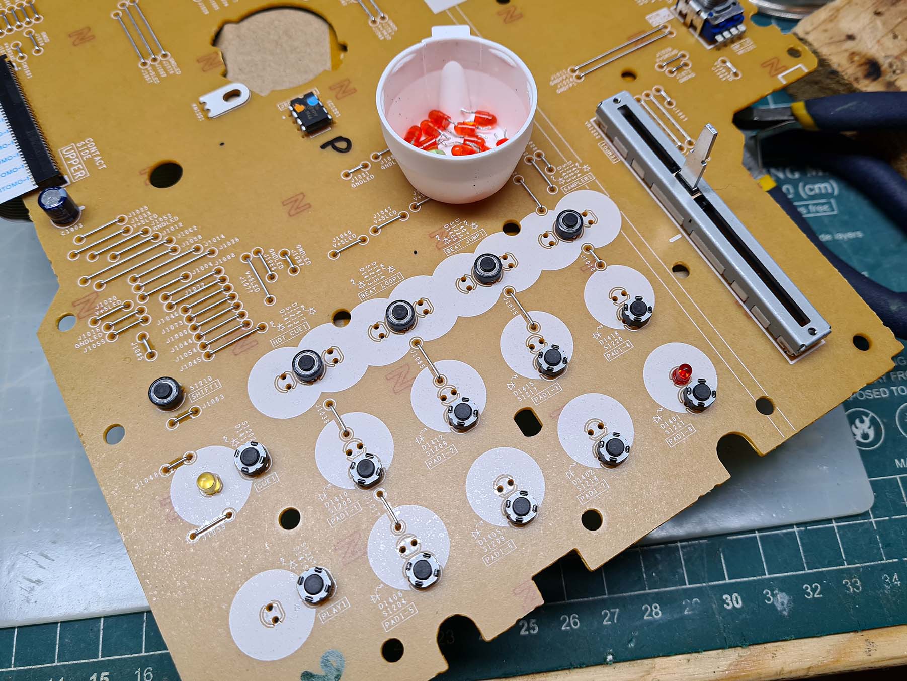
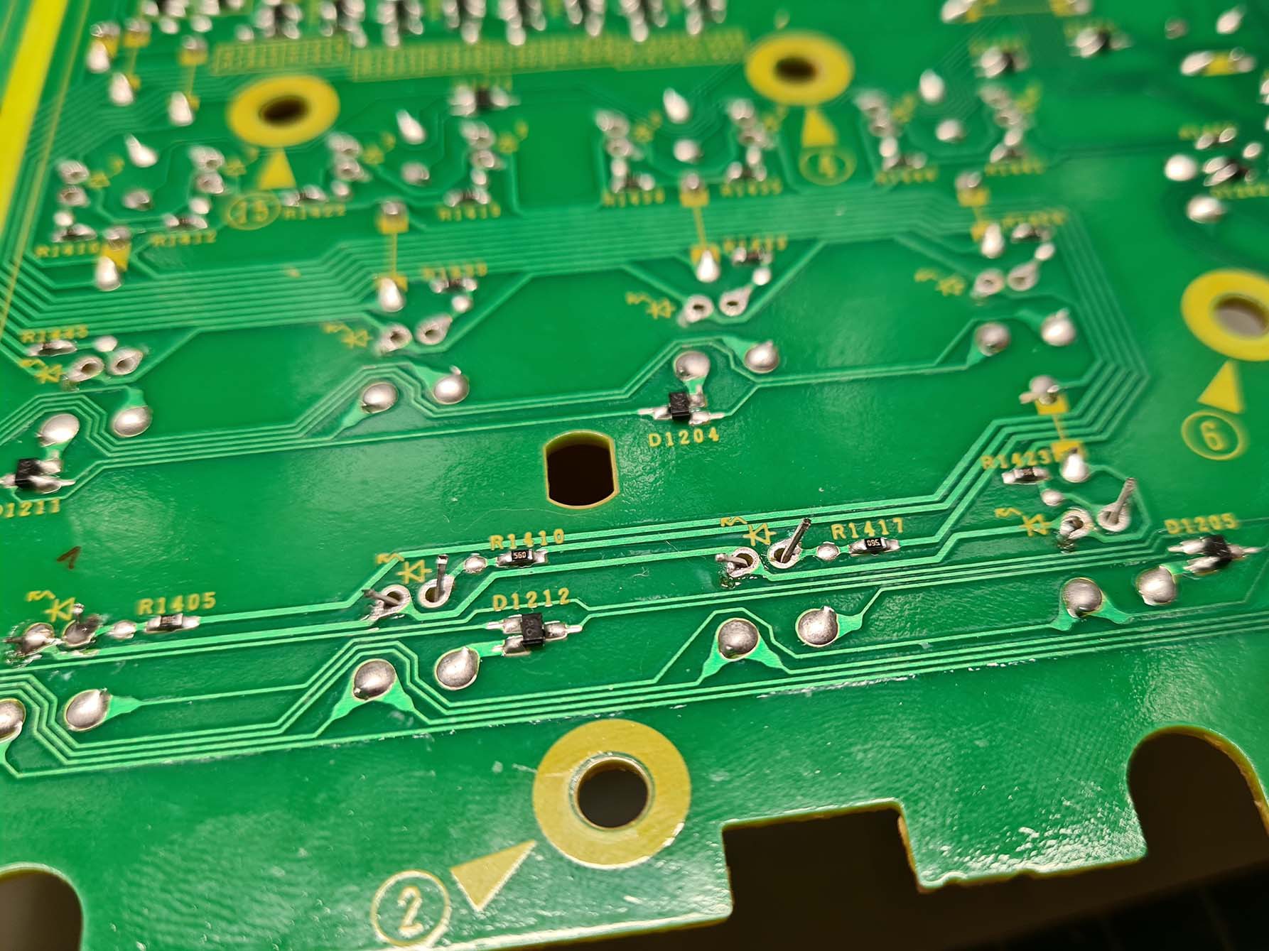
We first have to remove the headphone jack board, the logic board and carefully disconnect the flat flex cables. Then we remove the screws and are greeted by a rather simple-looking PCB:
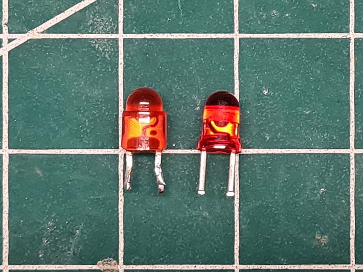
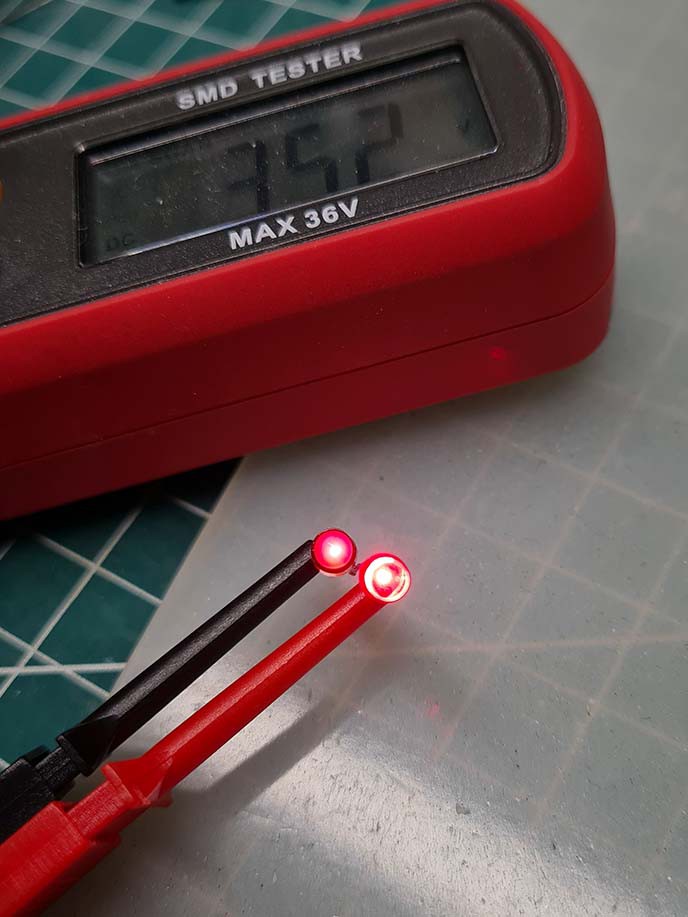
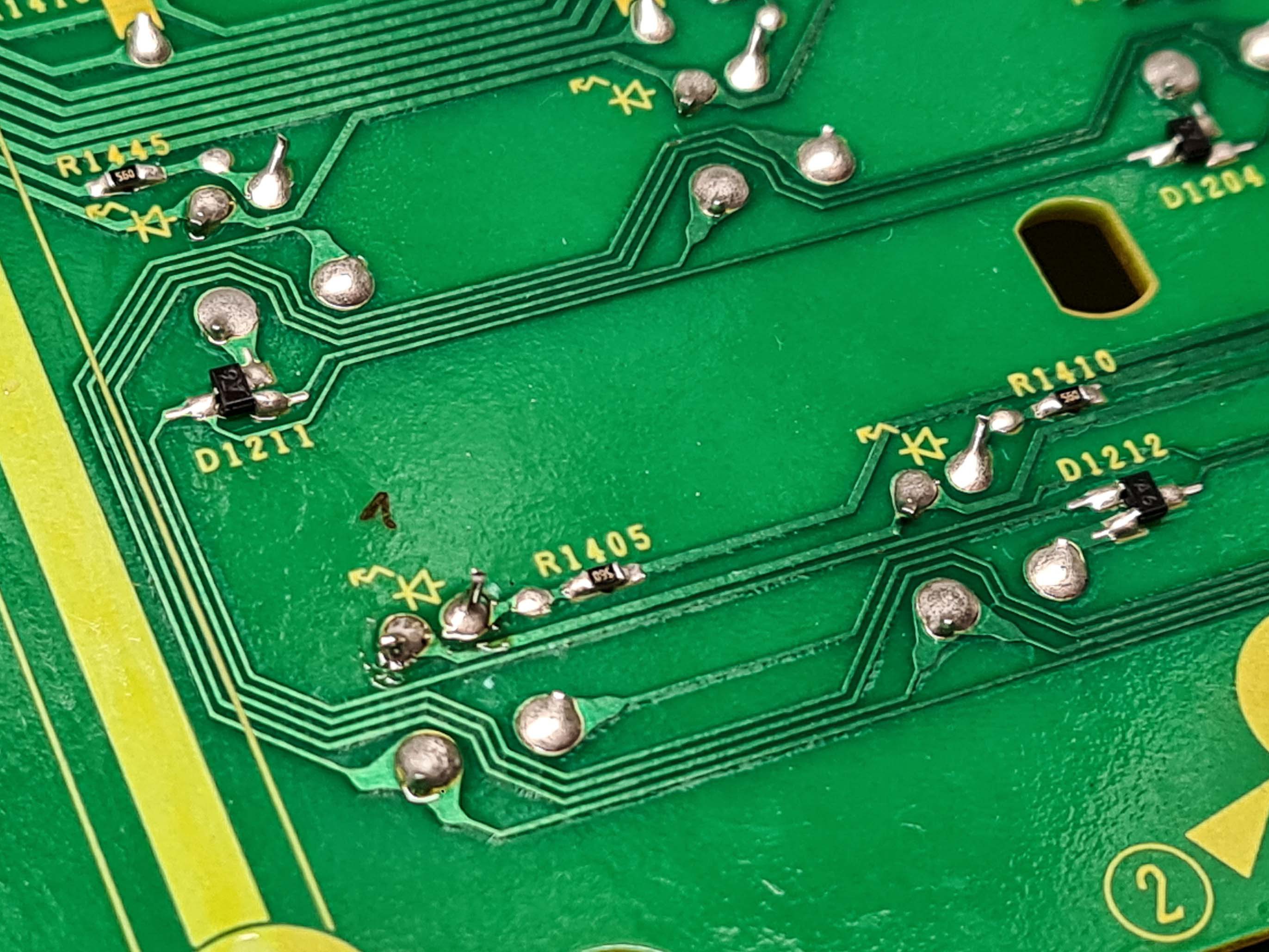
I started by swapping just one LED to have a comparison of how it looks. In the picture below, the left LED is the stock, right is the replacement. Rather annoyingly, the new LEDs don't have the flat side to indicate polarity and the larger internal metal pad is the anode (instead of cathode, which is more typical) - I'll have to pay careful attention to the polarity. Below they are shown running in series on an LED tester at about 1mA current. Already much brighter!
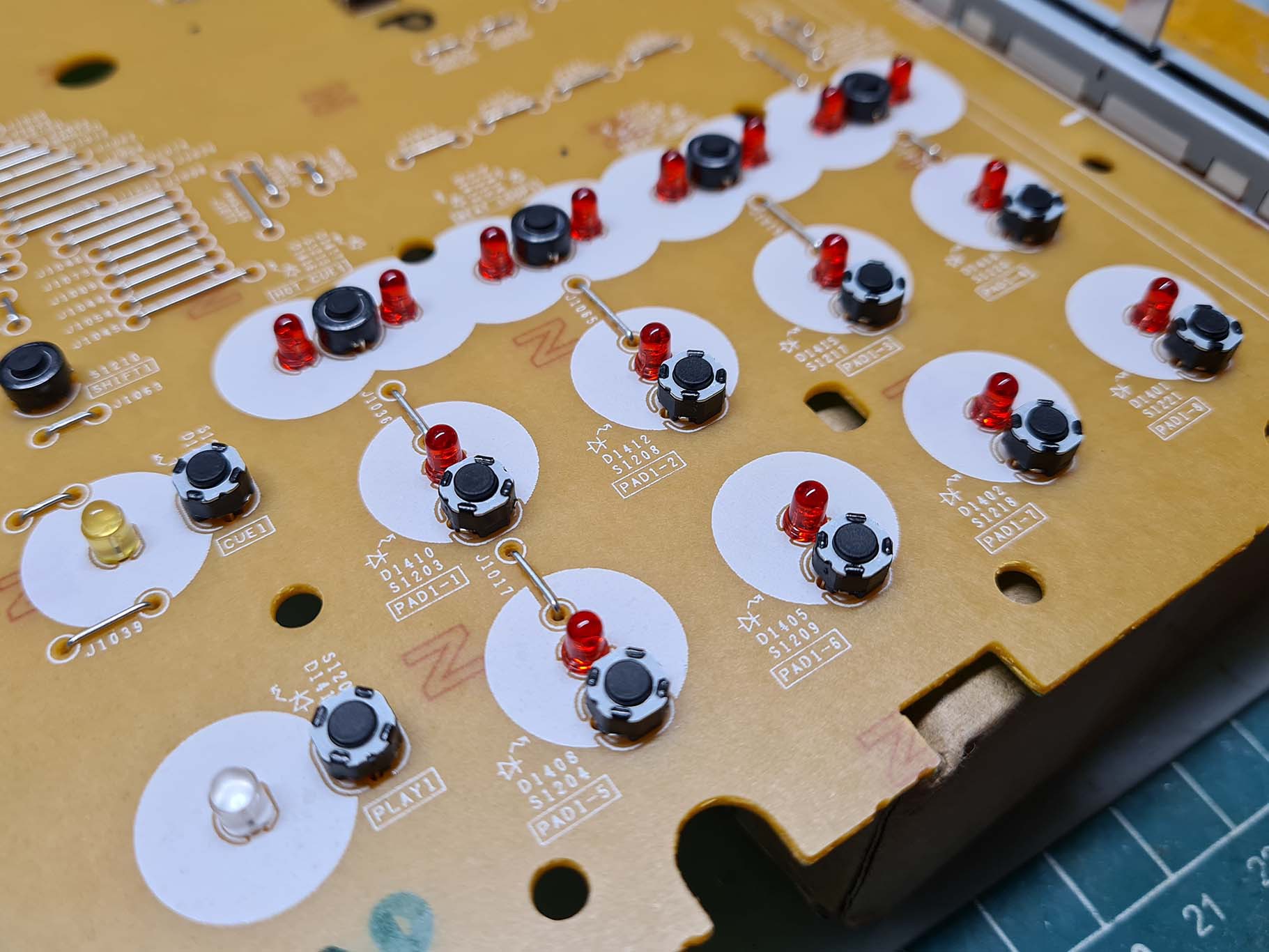
Notice that the LEDs leads are bent outwards to provide better mechanical reinforcement to the connection. These DJ controllers take a lot of abuse, which is also why they use so many screws to make the entire unit as rigid as possible. The bent leads are a bit of a challenge for desoldering, as they must be first heated up and bent back up before they can be desoldered. Luckily I have a desoldering station, which makes it pretty easy to do. After removing and swapping the LED:
Then I partially re-assembled the controller with just a few screws to hold the PCB in place and I re-connected the main logic board. Success! The camera actually makes the old LEDs appear brighter than they really are, but in person the difference in brightness is huge.
I was very happy with the result, so it was back to disassembling the PCB and replacing all LEDs of the left deck, including the Sync and Play buttons. First I desoldered the old LEDs, my desoldering station helped to greatly speed up the process.
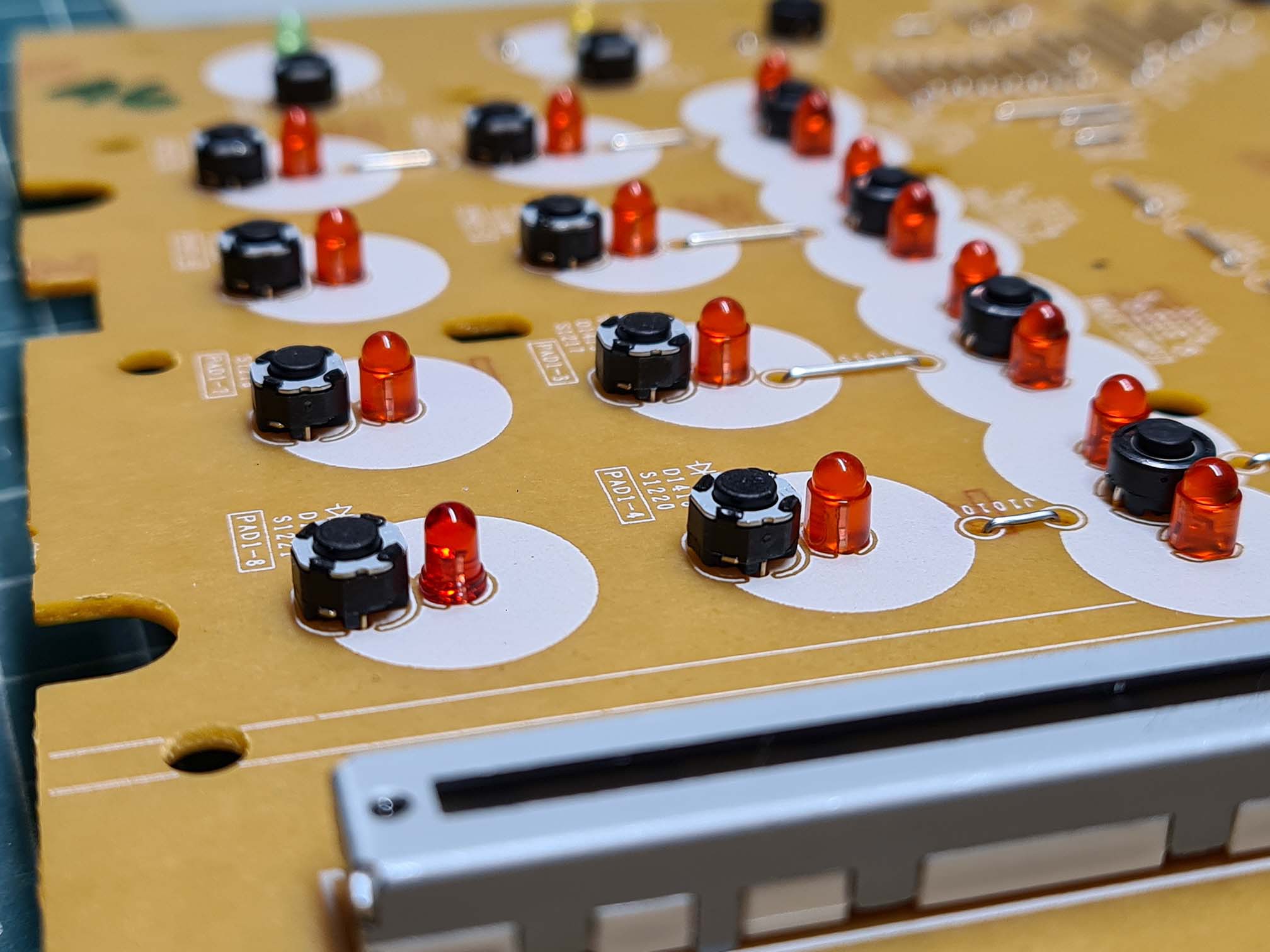
When inserting the LEDs, I bend their leads outwards like the rest of the components. To make sure that the LEDs are nice and square, I first add some solder to one lead to temporarily tack it in place. Then I re-heat the connection while pressing the LED with a finger against the PCB to properly seat it. Then I fully solder in both leads and trim the excess length from the leads.
All LEDs replaced:
And everything partially re-assembled to show the difference:
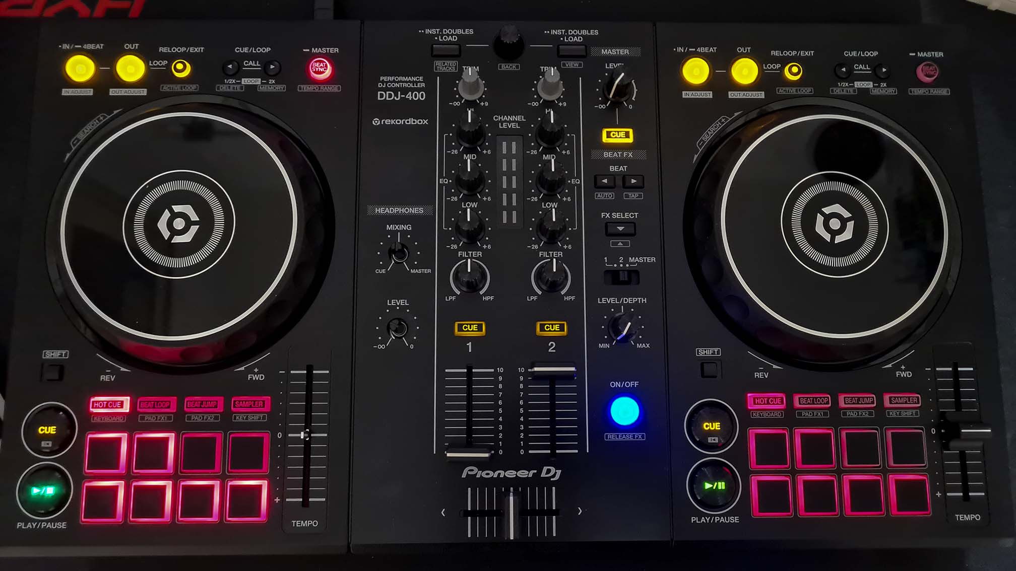
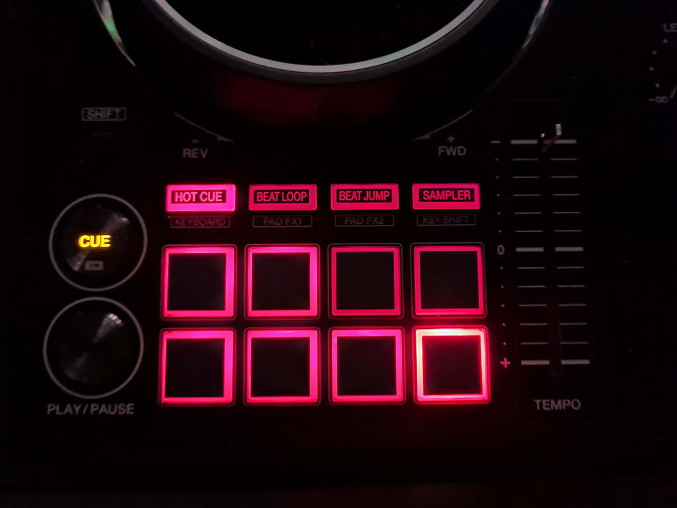
This was shot at night with regular room lighting. The camera slightly over-emphasizes the old pads, but the pads of the left deck are much brighter in person. The Play button is perhaps a bit too bright, I think I will just change the 270R current limiting resistor to something higher. The resistor is easily accessible without having to remove the PCBs from the controller.
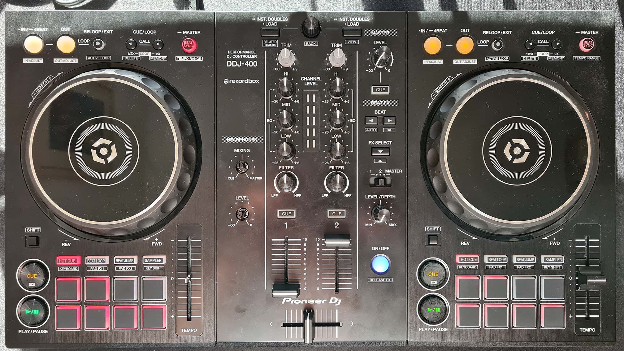
This is during the day with indirect light. The left deck LEDs are clearly visible, whereas the right deck LEDs are basically invisible. Of course, even the new LEDs are swamped out when the sun shines directly on the pads, but you can see them if you just shade them with your hand. With the old LEDs, you would struggle to see them even while shaded. You could in theory use even brighter LEDs, but I think that they would eventually become too bright for night time use.
Everything is looking good, next step is to modify the right deck.
Discussions
Become a Hackaday.io Member
Create an account to leave a comment. Already have an account? Log In.