 Adam Trizuljak
The left deck was a success, so I removed all remaining knobs from the controller and removed the right deck and mixer PCB. Note that the volume fader and crossfader knobs use a locking mechanism, removing them is also shown in Cameron Gray's teardown video. This is the PCB after removing it from the case:
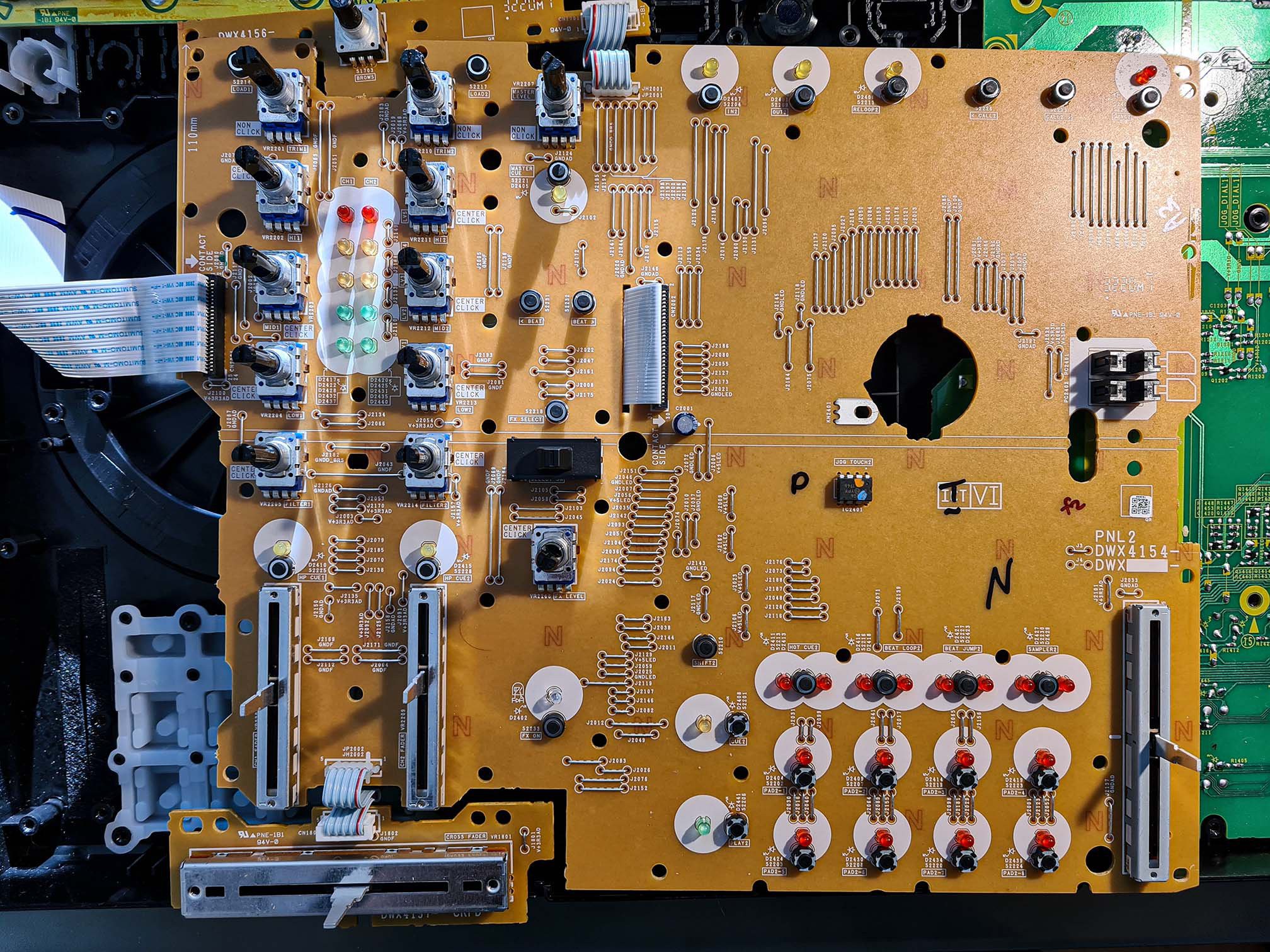
The process to replace the LEDs is exactly the same as with the left deck, in fact I didn't even bother to take a picture after swapping them. While I was here I also considered to replace the red LEDs in the audio level indicator, because they too are pretty dim. But it turned out that the replacement LEDs don't illuminate the level indicator window evenly, they were causing a hot spot in the middle. It didn't look good, so I abandoned this idea.
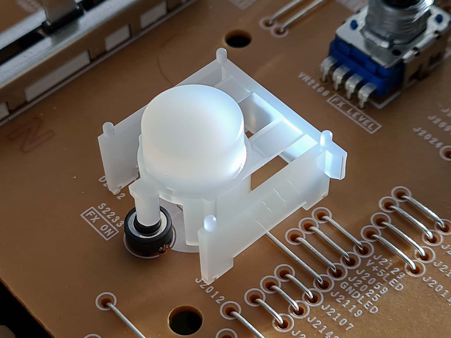
Again, let's take a moment to appreciate some clever engineering. All buttons on the controller are constructed as levers where the actual switch is placed at the lever's end. Mechanical advantage is used in two ways: first, to reduce the force applied to the actual switch (did I already mention that these controllers get abused like there's no tomorrow?). And second, it also reduces the travel distance required to actuate the button, which provides faster and snappier response to the DJ who is trying to hit the buttons exactly on the beat. The lever also incorporates depth stops that are just long enough to allow the switch to be actuated, but then they come in contact with the PCB which prevents excess force from being applied to the switch itself.
At this point I tested that all LEDs are working and I proceeded to re-assemble the controller. I thought I was done, but then I noticed that all potentiometer knobs were misaligned by about 2mm to the side. Everything was working fine, but the asymmetrical knobs looked just terrible. So it was back to loosening all 70+ screws and carefully aligning both PCBs. I started with the left deck, only slightly tightening screws 1 and 2 and adjusting the PCB until I was happy with the position of the Headphones Mixing and Level knobs. Then I tightened screws 1 and 2 (being careful not to shift the PCB around) and then I tightened all the remaining screws in their designated order. Then I repeated the same process with the large right deck PCB. It took me an hour of fiddling to get the alignment just right, and having an electric screwdriver probably saved my wrist from an RSI.
Previously I mentioned that the new green Play button LEDs were a bit too bright, so before closing the controller I decided to change their resistors (R1465 and R2489) from the original 270R to 680R. This makes them less retina-piercing in the dark, but they remain very well visible even in sunlight. The Cue buttons now were a bit dim, so I also changed their resistors (R1432 and R2416) from 150R to 100R. All resistors are SMD 0603 size. The good thing is that the resistors are accessible just by removing the rear cover of the controller, you don't have to disassemble the PCBs.
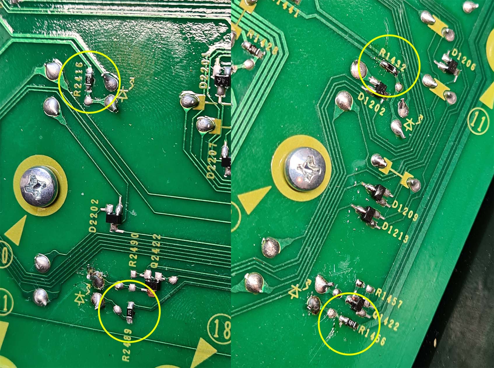
Here you can see the modified resistors on the left deck vs. the original right deck.
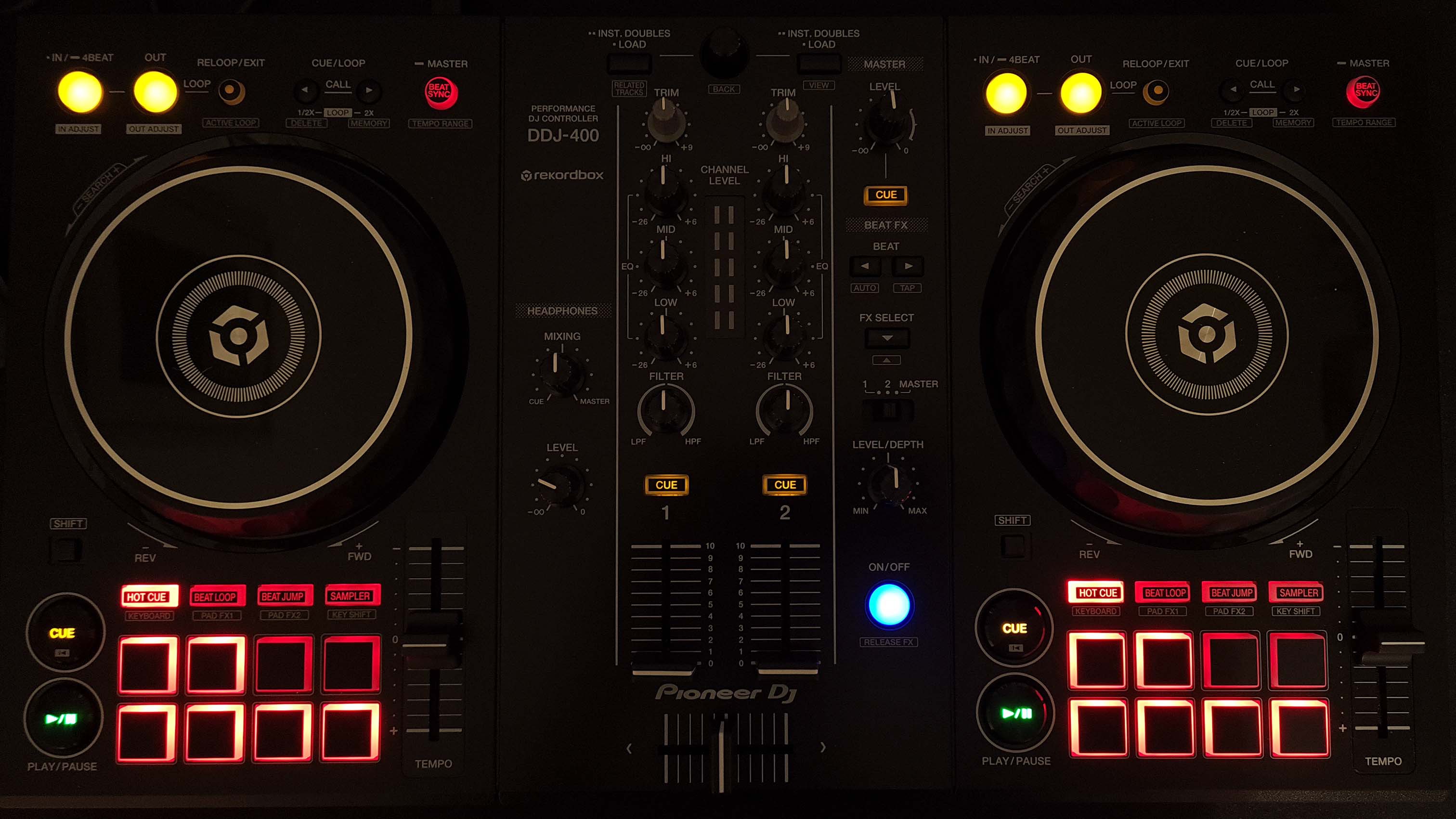
And that's it! Honestly, swapping the LEDs is pretty easy and takes less than an hour, but the disassembly, alignment and re-assembly were much more tedious than I expected. But in the end I really enjoy the brighter pads, it was totally worth the effort. The design of the controller makes it pretty easy to repair, replace broken components or perform modifications.
Discussions
Become a Hackaday.io Member
Create an account to leave a comment. Already have an account? Log In.