 Ken Yap
Before presenting the boards, I will set down my goals for this project. Non-goals are to make the thermometer work again, or even to reuse the logic chips, the equipment is long obsolete. Thus my interloper UART board previously pictured has been removed as I have no intention of using that again.
- Drive the nixies with data from a wireless MCU like the ESP8266 or ESP32
- Use a shift register to minimise the amount of GPIO pins and wiring. For 6 digits (BCD), 24 parallel output lines suffice
- Disconnect the power from unused parts of the circuit to save power
- Later: Eliminate the use of the transformer power supply and feed it from a small SMPS with a boost converter for the nixie HV. The unused boards would be left in place, might as well store them there in the unlikely case posterity delves into 70s circuits.
From observation of the thermometer in action, I believe the analog circuit converts the voltage to a digital value, and then load and hold registers update the input to decoders for the nixies at regular intervals. So my aim is to drive the nixies after the registers with the minimum of board modifications.
First the analog board:
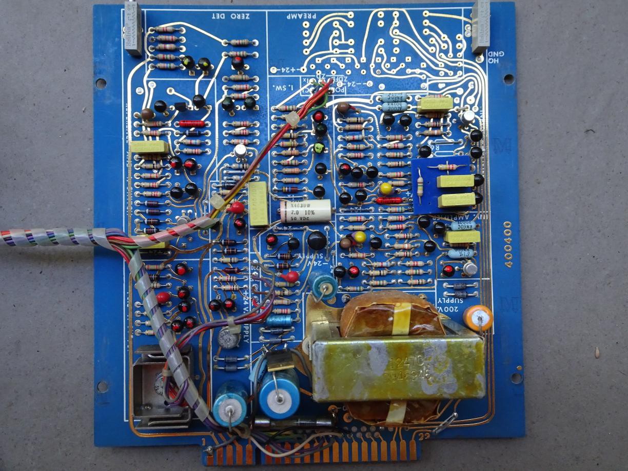
As you can see it contains only discrete actives, no ICs used. What complicates matters is that not all the external connections go via the edge connector. There is a wiring loom to the digital board. The connections may be of help to trace the function so I'm keeping the boards together for now.
Next the digital board:
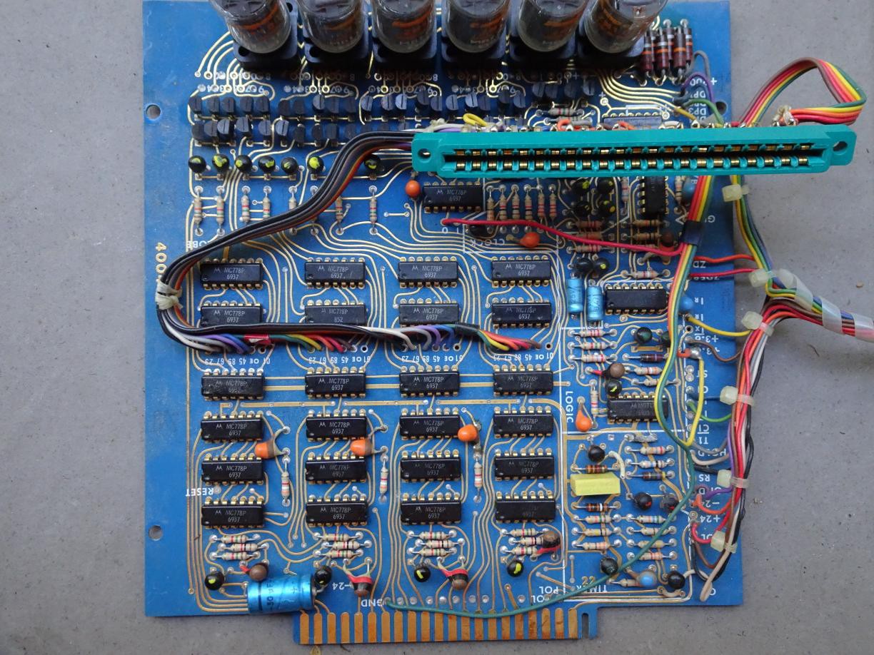
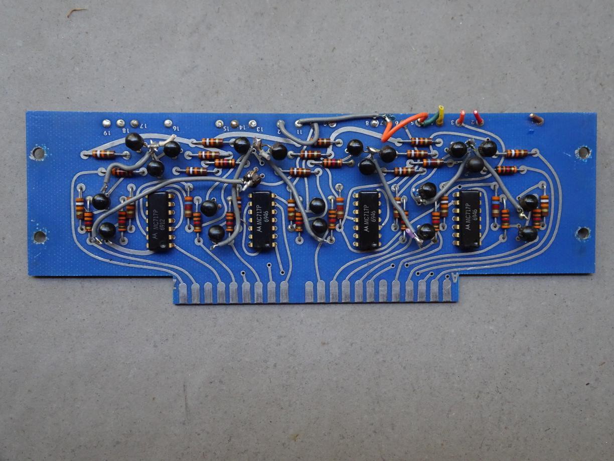
The connector goes to the comms board, which I'll present here, but is probably not needed. Again the connections may help work out the functions of the chips.
All the chips I can see are the MC778, which is a RTL dual D flip-flop. I managed to find the datasheet for it which will help trace the circuit.
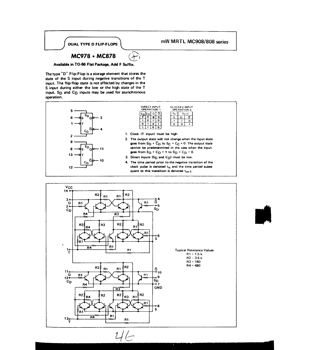
Interesting that the power supply should be between 3.0 and 3.6 V, I guess to limit power dissipation.
Returning to the logic board, it looks like there are a whole bunch of transistors for driving the nixies. So I'm guessing that the BCD to decimal decoder is implemented in discrete logic. (TTL 7441s were in the future.)
Discussions
Become a Hackaday.io Member
Create an account to leave a comment. Already have an account? Log In.