 ClimbinElectronics
So, on to the software side of things.
The software was reused from another project. It has some logging capability, a control loop which runs at 8khz in an interrupt. The LCDs and uarts and other peripherals are serviced in one freertos thread.
After fiddling with the PWM outputs for a while, that part worked as it should. Some safety features were added to make sure the PWM outputs would stop directly if something was wrong. The scariest thing is still that you are able to short circuit the input capacitors with the H bridge when something goes wrong. Nothing you can really do about that, just hoping the STM32F405 does not glitch out. If the DC bus voltage dips or rises too high, the outputs are disabled. When enabling the PWM outputs, a lot of power was used, I figured this was due to the system not having dead time between the high and low side of the H-bridge, so you get shoot through currents. After enabling dead time and fiddling with the amount, the problem was solved. For now, a dead time of 70*125ns=7us seems to work quite well, it has the lowest idling current.
A PC GUI was made, SB2500-Trainer, to be able to change set points on the fly.
For now, the controlloop generates a Sinusoid waveform at 50Hz, with a variable amplitude which can be set in the SB2500 trainer. The voltage is slowly ramped up and down to make sure the transformer does not draw too much current at the start.
An input voltage of 170 volt was applied, and the whole contraption tested. I can now ramp up the output voltage to 100VAC and light a lightbulb with it! The inverter idles at 35 watt @ 170 volts input voltage, which is ok.
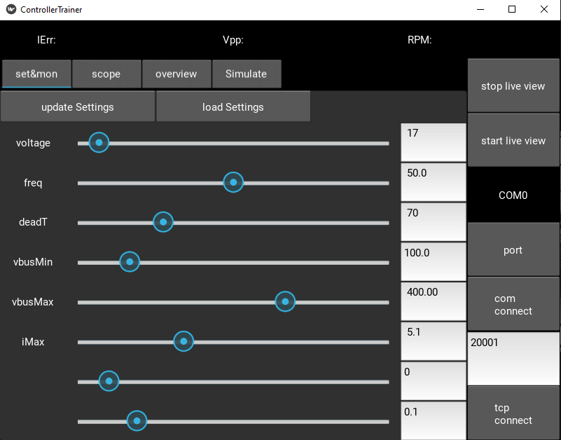
The controller PCB control GUI.
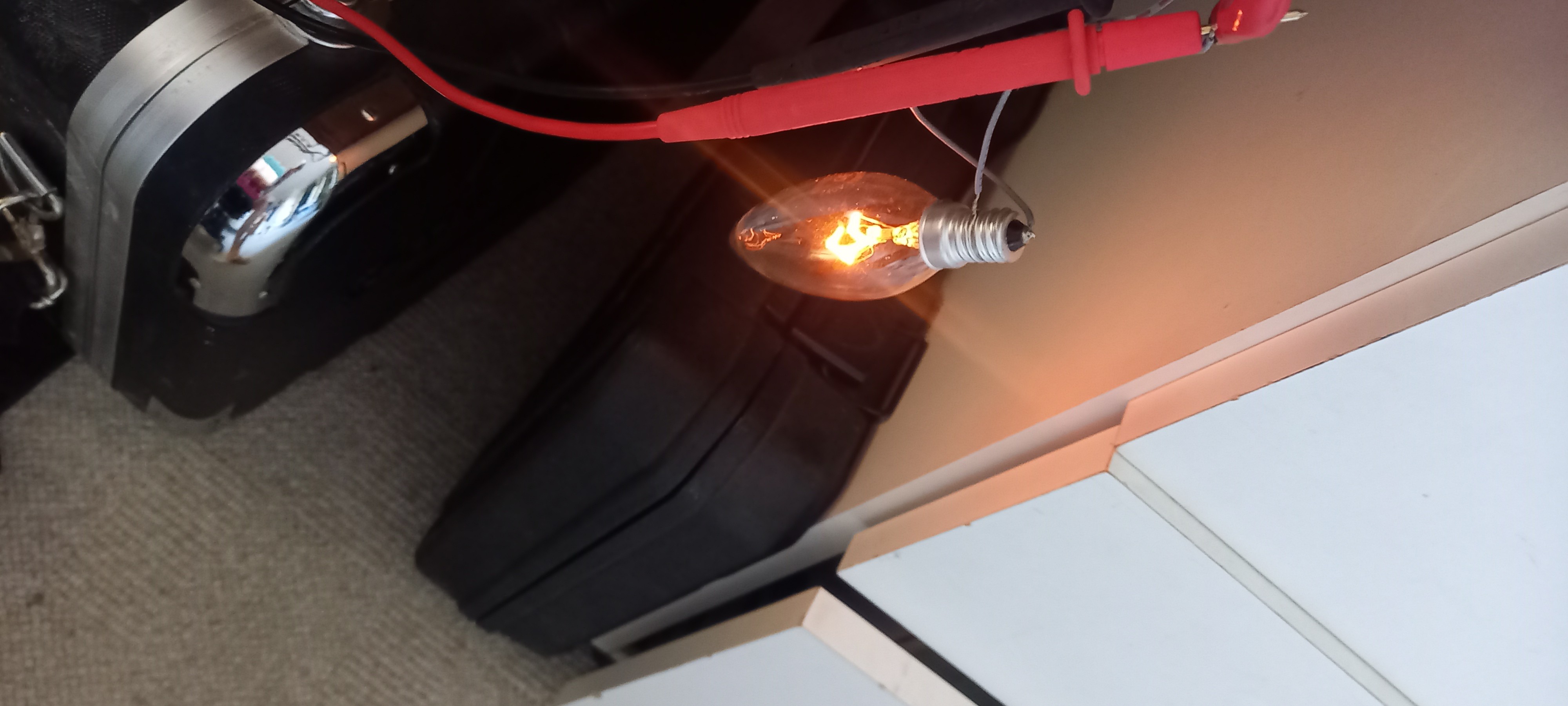
The lit lightbulb at 100VAC
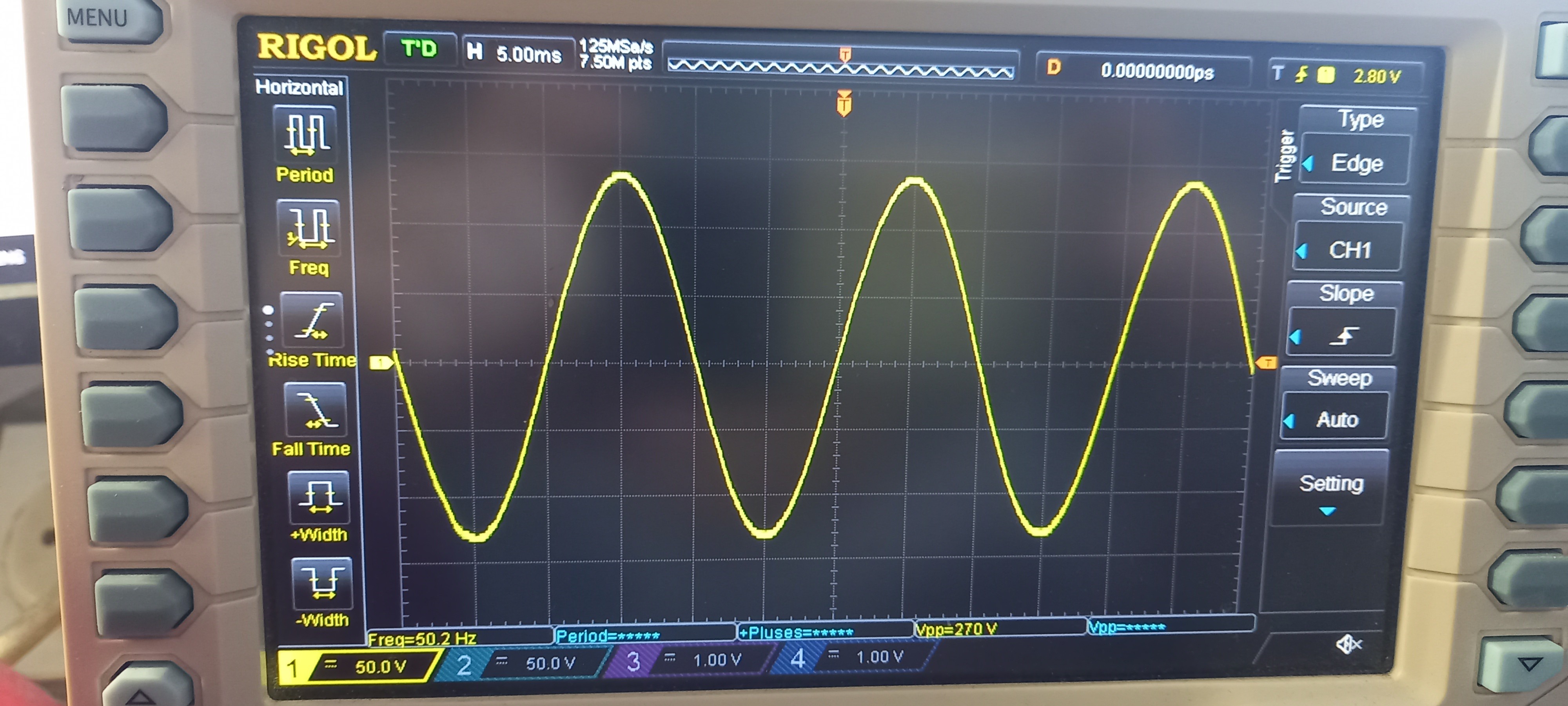
The output waveform, seems nicely sinussoidal.
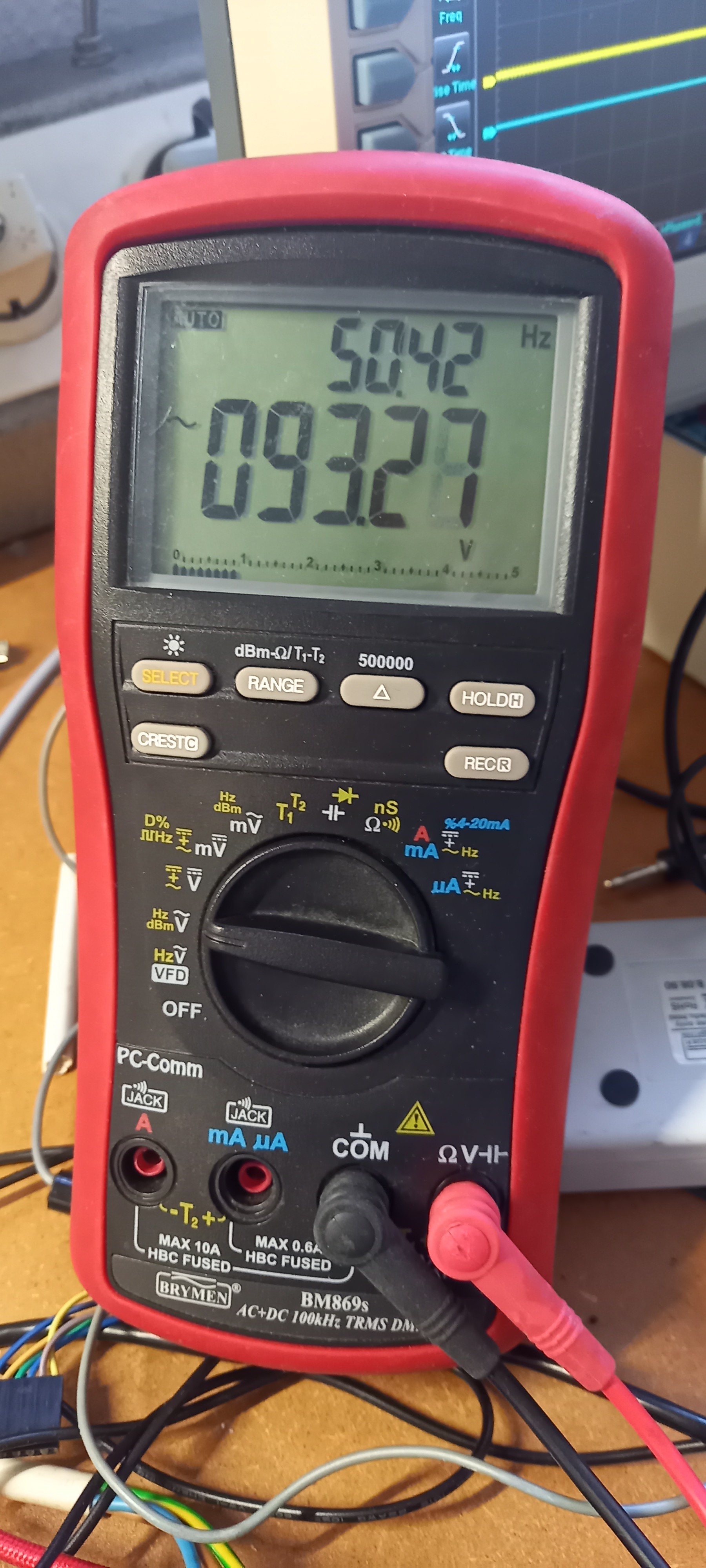
The output voltage and frequency.
Discussions
Become a Hackaday.io Member
Create an account to leave a comment. Already have an account? Log In.