 Stefan Krüger
for tuning i followed more or less the tutorial PID Without a PhD from Tim Wescott and the tutorial and video from PID Explained Team.
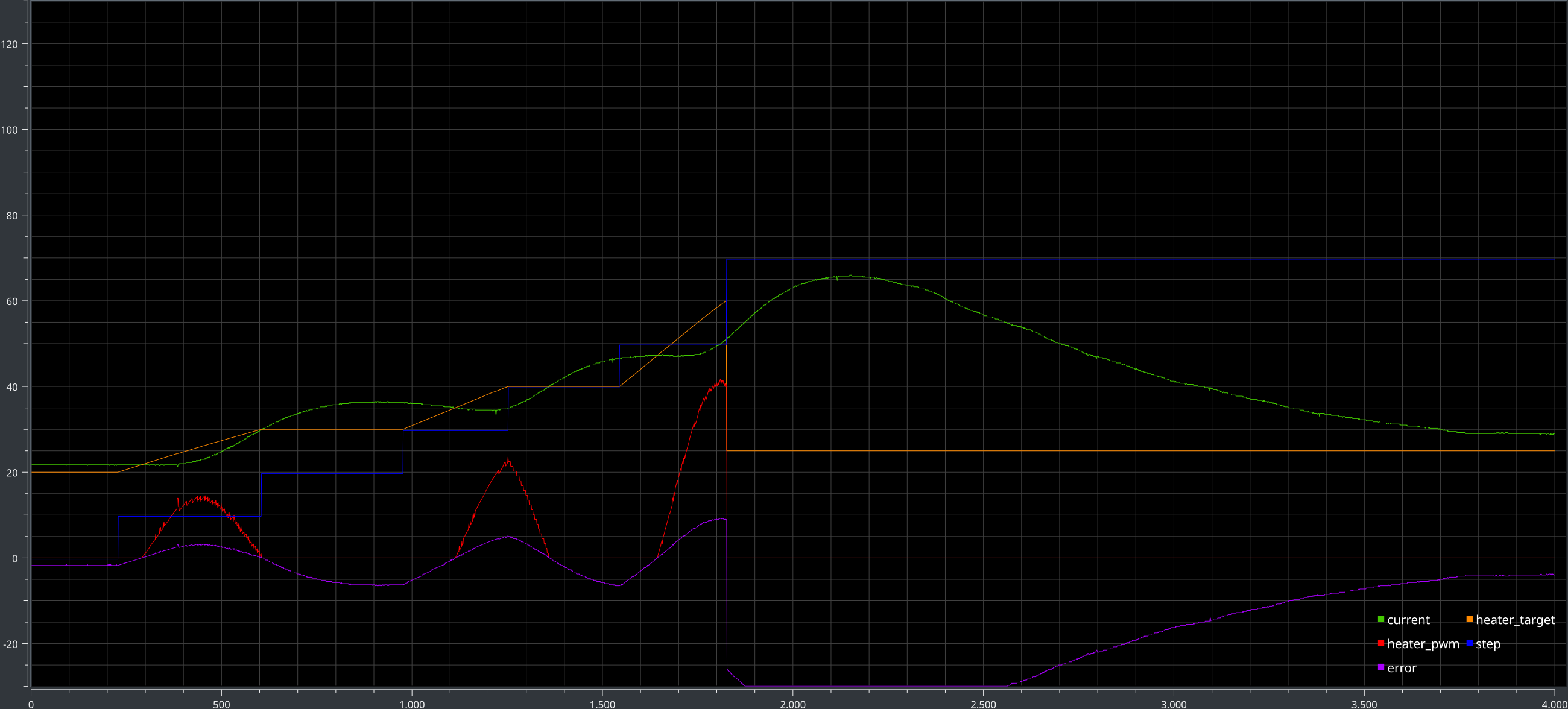
first i just checked with low temperatures of 20..40°C as i went on and tested up to 260°C i noticed that the current did decrease. and the temperature did not increase any more. i could see this in my graph as the heating got slower and slower with the rising temperature… (also the pid already saturated at the output..)
so i measured the resistance during the cool down of the heating elements to get some insights: (4x in series → 48V/4=~12V/Module)
| Resistance (Ohm) | Power @48V (W) |
|---|---|
| 40 | 57 |
| 39 | 58 |
| 38 | 59 |
| 36 | 60,5 |
| 38 | 60,3 |
| 34 | 64,8 |
| 26 | 88,6 |
| 24 | 96 |
| 22 | 104 |
| 20,9 | 110 |
| 19,5 | 118 |
result: the ~57W is not enough to get to more than 255°C…
i rearranged the Modules into 3-in-series connection. this means ~16V/Module – and tested again:
| Resistance (Ohm) | Power @48V (W) |
|---|---|
| 27,5 | 70 |
| 27,0 | 72 |
| 26,6 | 77 |
| 25,6 | 80 |
| 25,3 | 82 |
| 24,1 | 86 |
| 18,8 | 100 |
| 17,5 | 130 |
| 16,7 | |
| 15,6 | |
| 14,3 |
with this i found that i can go above 255°C.
i then tested the profile for the Felder ISO-Cream “Clear” and found that in the reflow stage the heat-up is a little to slow:


so i again switch the configuration – now i have a 2-in-series config: 24V/Module CURRENTLY THIS TABLE IS ONLY CALCULATED VALUES!!
| Resistance (Ohm) | Power @48V (W) |
|---|---|
| 20 | 115 |
| 19,5 | 118 |
| 19 | 121 |
| 18 | 128 |
| 17,5 | 132 |
| 17 | 135 |
| 13 | 177 |
| 12 | 192 |
| 11 | 209 |
| 10,45 | 220 |
| 9,75 | 236 |
i also tested this with the Felder profile:

this time the heat-up is fast enough! 🙂 the nice and working pid tuning i had for the 4-in-series arrangement is now out of tune… so i will have to re-tune it to get less overshoot / swing.
while having a break i thought about the maximal power in this configuration – and found that this way i only be able to power 2×2 modules with my 250W power supply. for now i leave it this way. in the long run i hope with the other frame concept i get more heat to the pcb and less into the stone and this way be able to use the 3S config.
Tuning
after a day of mostly waiting til the system cooled down again – one test cycle <=60°C needs 400s → 6:40min – i just rebuild my hw mounting setup.
![new setup]()
new setup ![]()
details of mounting


this way i can warm up quicker and cool down much quicker as i do not store heat in the stone. – at least that is what i hope..

hmmm – does not seem to change much..
i then tested the actual Felder Profile:
seems i have a working profile. i will add a little more time for the prepare phase. so the pcb is really fully at the 50°C. at the top i have a little bit of a mis-match – i saw on my temp sensor directly connected to the heating elements at the top ~265°C – so that is hot… the pcb seems to increase its temperature resistance at higher temperatures… at the peak i have 230°C to 245°C error. and to the heating this results in ~35°C difference…
i will report when i solder the first real board. 😉
Discussions
Become a Hackaday.io Member
Create an account to leave a comment. Already have an account? Log In.