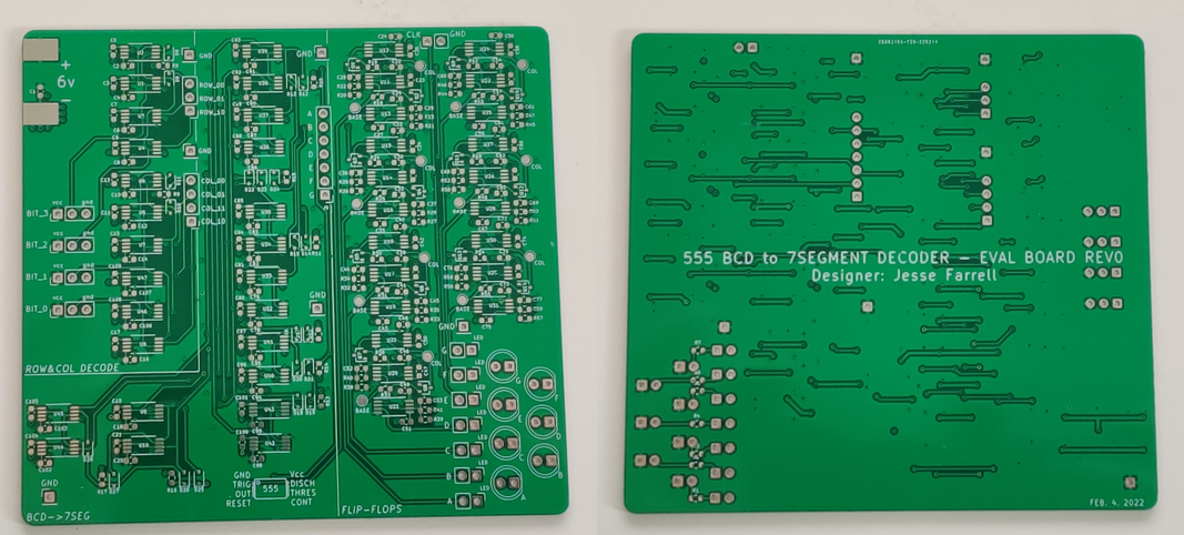
The BCD to 7-segment decoder circuit schematic and PCB are shown below.
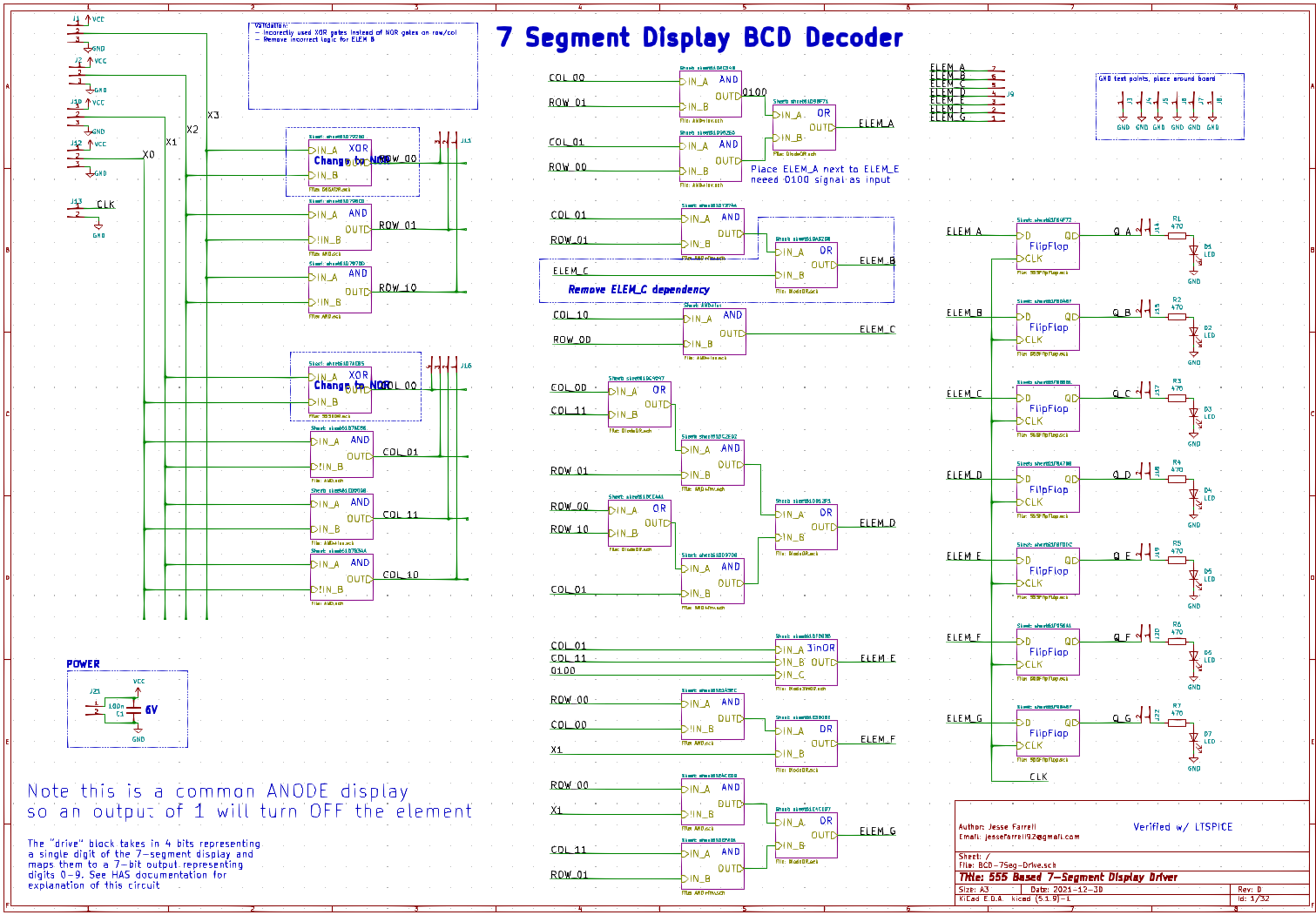
Two errors were found in the decoder circuit. When translating the LTspice circuit to KiCad I mislabeled the NOR gates as XOR, leading to incorrect row 00, and column 00 decoding. The second error was an extra dependency for element B of the seven segment display (shown below).
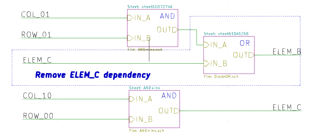
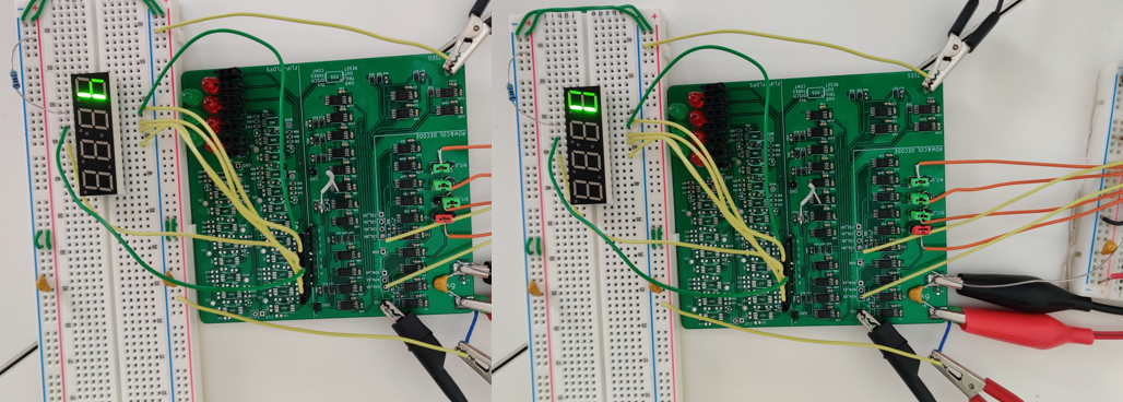
After soldering a 74 series NOR gate into the circuit (to bypass the XOR gates), and removing the OR gate shown above, the circuit worked as intended. Two digits are shown below. Note that some elements are dim since I’m looking at the unbuffered outputs of the logical blocks, before the flip flops (so some have 2k to GND, others are driven directly by a 555 output).
One more error was found while working on the final board layout, I managed to flip create a backwords 6 "∂". I've correct this logic and reran the simulation.
Discussions
Become a Hackaday.io Member
Create an account to leave a comment. Already have an account? Log In.