Now let's look at one of the examples provided on the repo. This example is meant to represent a low-power system which operates from a coin cell.
# First, define all threads. This is how we define which components are on, how much current
    # they need, and how long they are on in different modes. All threads are periodic and run forever
    baro_thread = epm.Thread(name="Barometer", stages=[
        epm.Stage(delta_t_sec=0.002,components=[
            epm.Component(name="Barometer-BMP390",mode_name="Sample",current_ma=0.660),
            epm.Component(name="Microcontroller-ATSAML21",mode_name="Active",current_ma=0.6),
        ]),
        epm.Stage(delta_t_sec=0.03,components=[
            epm.Component(name="Barometer-BMP390",mode_name="Sleep",current_ma=0.0014),
            epm.Component(name="Microcontroller-ATSAML21",mode_name="Active",current_ma=0.6),
        ]),
        epm.Stage(delta_t_sec=10.0,components=[
            epm.Component(name="Barometer-BMP390",mode_name="Sleep",current_ma=0.0014),
            epm.Component(name="Microcontroller-ATSAML21",mode_name="Standby",current_ma=0.0025),
        ])
    ])
The ultra-low power microcontroller ATSAML21 is used alongside the barometer BMP-390. The operation is simple. There are three stages to the operation. In the first, the barometer is on and being sampled, and the microcontroller is active. In the second, the barometer is asleep and the microcontroller is active (performing some calculations on that data), and then in the third stage, both devices are in a sleep mode.
Next, let's look at how a regulator is defined!
# Next, define all power rails based on their voltage regulators
# Consider TPS7A02
reg_1v8 = epm.VoltageRegulator(name = "1.8V Rail", output_voltage=1.8, is_switching=False, threads=[baro_thread], quiescent_current_ma = 0.000025, max_current_output_ma=200.0)
Here, we consider an ultra-low power regulator the TPS7A02. This is not a switching regulator. We set the voltage level at 1.8V, and provide the quiescent current and maximum current from the datasheet. After the latest updates, we connect threads to a regulator.
After defining the voltage regulator, the battery is defined.
# Then, set up all sources and energy harvesting
source = epm.LithiumCoinCellBattery(name = "210mAh, CR2032", number_cells=1,regulators=[reg_1v8],capacity_mAh=210.0,initial_charge_mAh=210.0,
                                internal_resistance_ohm=60.0)
This model is of a CR2032 coin cell. After the latest update, these tools include not just a lithium ion cell but also lithium primary coin cells. The difference is in the voltage vs. state of charge curve. After these updates, we attach regulators to a battery.
Finally, let's see how to setup the whole system and simulate!
this_sys = epm.EmbeddedSystem(name="Coin Cell Example", sources = [source])
this_sys.power_profile(sim_time_sec=10*86400.0, record_time_history=True)
this_sys.print_summary()
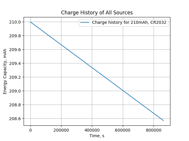
this_sys.plot()After the latest updates, we attach a set of sources (batteries) to a system, and then can simulate for a configurable amount of time. The print summary method prints out some useful information about the net energy for each regulator and battery life for systems which do not recharge.

The plot method provides some useful plots which summarize the performance over the simulated time, such as the discharge status shown below.
Discussions
Become a Hackaday.io Member
Create an account to leave a comment. Already have an account? Log In.