 El Juanan
The tube driving the horizontal deflection is V5. The X shift is drien by a variable internal resistor, in series with a 440K resistor. In that configuration, The beam never went far from the center-right of the screen with the variable resistor set to the minimum, and in the maximum the beam went far to the left side. I changed R32 to a 150k resistor so the beam could go a little bit more to the right, but it wasn't necessary as I found out later.
I was not aware of RC resonators so the circuit looked kinda odd to me, but after making some google searchs I found a circuit very familiar, a Miller integrator. With the switch S1, different capacitors are used, so the frecuency changes too. A variable resistor (P5) is used to adjust the time base even more. Something is clearly wrong here, the oscillator is here, but it doesn't work. I proceeded to leave it working alone, without any other part of the circuit. I disconnected R24 which feeds the triode of V5, which then connects to the pentode. The oscillator works! I could set the frecuency with the dial and the selector, pretty neat if you ask me.
So there is something wrong with the triode or its circuit, maybe with V4, but wait a second.
You see, the selector also switches into two capacitors and a internal variable resistor which also looks like a oscillator, but with V4 being the tube driven. I see a resistor that doesn't look original (R46). I remove it and voilà:
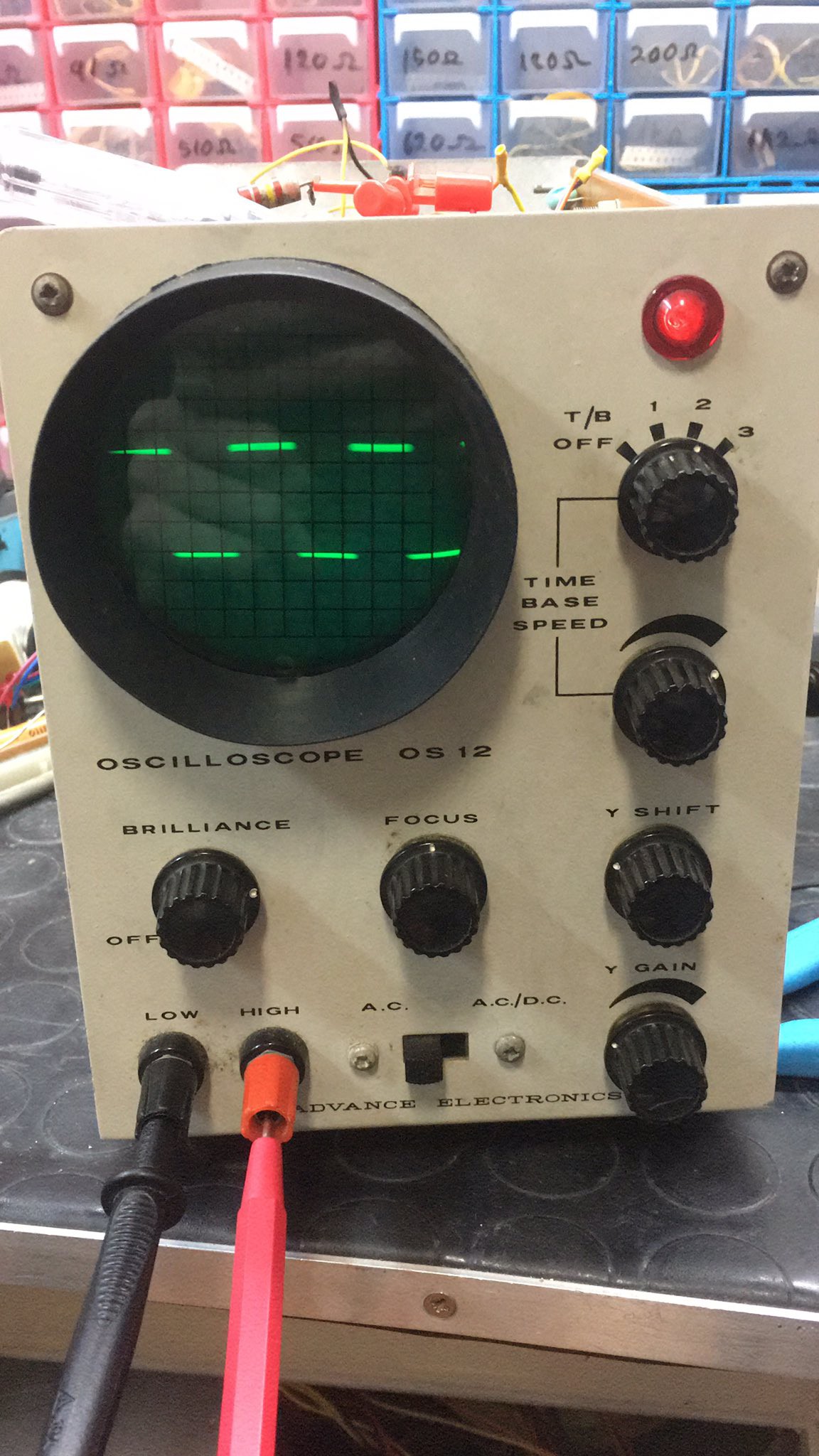
The thing just worked. It was maybe a weird unfinished mod. The variable resistor is now doing nothing. It is marked on the board as "stability", kind of ironic. I tested what to sustitute that resistor for, and even with a 10Mohm resistor the scope stops working, a capacitor doesn't affect the behaviour, so I just let it be.
TO-DO: fix that part. I'm almost sure the variable resistor doesn't hast to be connected to V-, maybe to 0V.
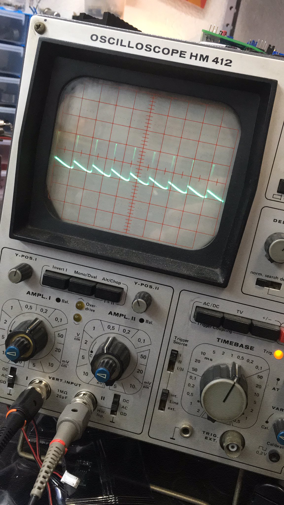
Lastly, the ouput of V5, a really neat sawtooth waveform.

I hope this work helps someone fix their scope. Thank your if you've read this.
Discussions
Become a Hackaday.io Member
Create an account to leave a comment. Already have an account? Log In.