 El Juanan
First thing to do is obvious: get the more obvious wiring: the main connector, the power supply and the vidicon connector, and also a nine terminal socket that has wired lots of coils. The numbers you see in the diagram are the numbers I gave to each wire. They appear to be random numbers because I didn't really started from here, but it's the best way to explain the circuit.
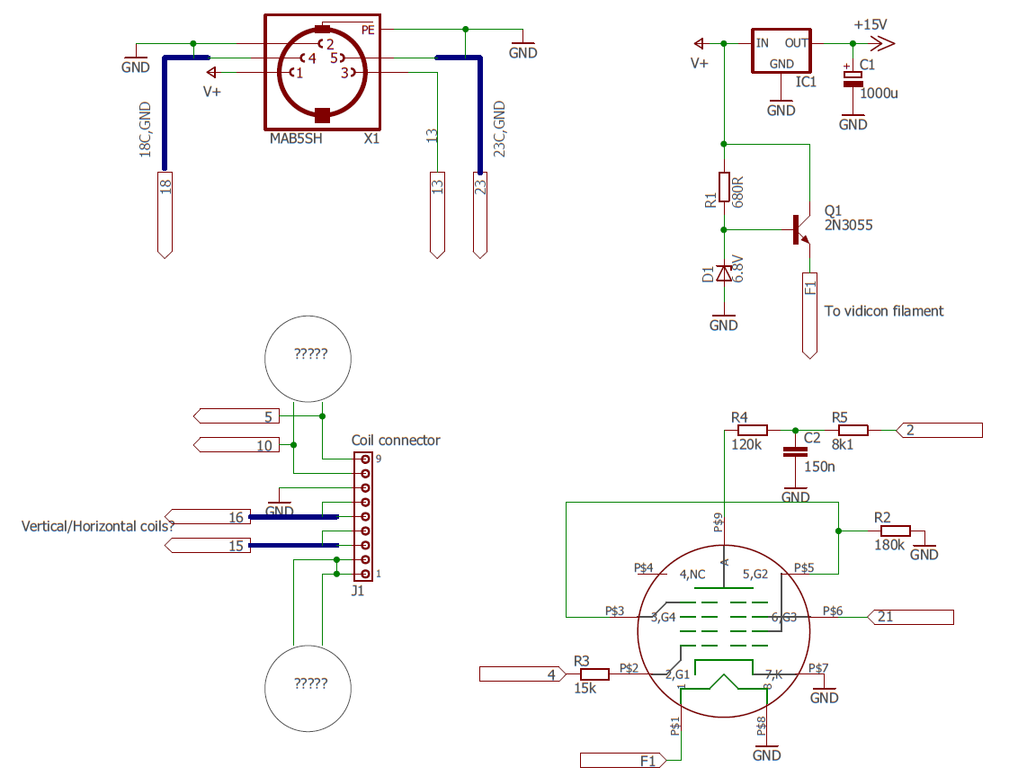
The connector isn't a 5 pin DIN, but it doesn't matter for the schematic. The position of the contacts is equivalent. This connector provides power via pin 1 (V+) and pin 2 (GND). There are 2 coax cables (18, 23) connected to pins 4 and 5 respectively. There is a fifth wire (13) connecting to pin 3.
The power supply consists of an LM7805 in a TO-3 package and a 2N3055 transistor with a zener diode to provide a constant 6.3V to the vidicon filament. The 9 terminal sochet above the coils is connecting the vertical and horizontal deflection coils, which I can't differentiate yet; and there are another two pairs of wires going somewhere in that enclosure. Maybe some focus coil or something related? One of the pairs is shorted with a piece of wire, and is connected to nowhere else.
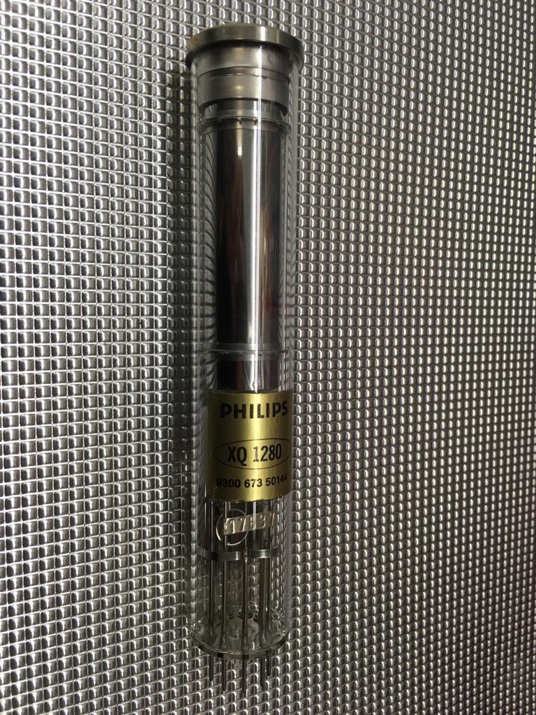
The Vidicon has 10 connections: 1 is the anode and is ubicated in the opposite extreme of the tube where the socket is, pins 4 and 9 are not connected and the rest are. I measure the cathode going directly to ground, I don't think that's quite right, but I'll leave that for now.
Next step will be looking at some of the pcbs.
Discussions
Become a Hackaday.io Member
Create an account to leave a comment. Already have an account? Log In.