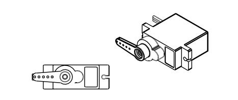
• 1
    Step 1: Adjusting Servo Motors Positions

    Before starting the assembly, we need to manually adjust the angle adjustment of the servo motors. Otherwise, your robot will not work properly.

    Attach the Servo Arm to the servo, and then slowly turn the servo arm clockwise until the arm stops. It's okay if the servo arm doesn't stop at the same angle shown in the picture above. The important thing is that we find the end point of the servo. Remove the servo arm from the servo and reposition it so that it is perpendicular to the servo body.

    Slowly turn the servo arm counterclockwise until it is parallel with the servo body as shown. This is the center position of the servo and it is important to center the 8 servos in the set before starting the assembly of the robot. After the servo arm is parallel to the servo body, remove the servo arm and set it aside for later assembly.

    If your servo motors are 360 degree analog servos, you cannot do manual cabling. That's why you can calibrate your servo motors thanks to the code I shared with you. As in the circuit diagram at the above (3), turn your servo motors into 1.2.3.4.5.6.7.8. Install the code at the bottom to your arduino by attaching it to the pins. If you do not do this, your robot will not work stably.

    Servo Calibration Code :

    #include <Servo.h>    // include servo library
    
    
    // Define 8 Servos
    Servo myServo1; // Front Left Pivot Servo
    Servo myServo2; // Front Left Lift Servo
    Servo myServo3; // Back Left Pivot Servo
    Servo myServo4; // Back Left Lift Servo
    Servo myServo5; // Back Right Pivot Servo
    Servo myServo6; // Back Right Lift Servo
    Servo myServo7; // Front Right Pivot Servo
    Servo myServo8; // Front Right Lift Servo
    
    
    void setup() {
      // put your setup code here, to run once:
      myServo1.attach(1);
      myServo2.attach(2);
      myServo3.attach(3);
      myServo4.attach(4);
      myServo5.attach(5);
      myServo6.attach(6);
      myServo7.attach(7);
      myServo8.attach(8);
      
      myServo1.write(90);
      myServo2.write(90);
      myServo3.write(90);
      myServo4.write(90);
      myServo5.write(90);
      myServo6.write(90);
      myServo7.write(90);
      myServo8.write(90);
    }
    
    
    void loop() {
      
      // put your main code here, to run repeatedly:
    }

    If you have done with the servo adjustments, you can pass to Leg Assembly stages.

  • 2
    Step 2: Leg Assembly Stages

    You have to make the leg connections by following the step-by-step visuals. You can make the connections by following the step names from the schematic. Repeat steps 1 through 10 exactly 4 times and build 4 legs :

    • Step 1 : Place a servo single arm on the pedestal pivot plate and screw the servo mounting screw into the servo single arm from the rear of the leg up pivot plate.
    • Step 2 : Attach a servo single arm to the standing servo arm and attach a servo mounting screw to the servo. Screw on the servo single arm from the back of the leg servo arm.
    • Step 3 : Attach a leg parallel joint to the leg piece using an M3x10mm screw and an M3 fiber nut.
    • Step 4 : Attach the leg piece to the leg servo arm using an M3X10mm screw and an M3 fiber nut.
    • Step 5 : Insert a Servo into the Servo Holder.
    • Step 6 : Insert the top end of the Servo into the Pedestal Servo slot.
    • Step 7 : Attach the servo holder to the leg Servo socket using two M3 x 12mm screws and two M3 fiber nuts.
    • Step 8 : Attach a leg parallel plate to the other end of the leg using the M3X10MM screw and M3 fiber nut.
    • Step 9 : With the servo rotated to the center position and the leg parallel joint positioned horizontally, attach the leg servo arm to the servo using the servo arm screw supplied with the servo
    • Step 10 : Attach the Leg Assembly from the previous steps to the Leg Bottom Pivot Plate using two M3 x 10mm Screws and two M3 Nuts.

    Leg Assembly was a little difficult, but believe me, if these stages are over, the rest is coming. If you have completed these steps, let's move on to the Body Assembly part.

  • 3
    Step 3: Body Assembly

    In this stage, you should be careful with the numbers. Schematics is explained according to the part numbers, so that you should read the lists that we created, before the asssembly ;

    Part List of Schema 1 & 2:

    • 1- Body Upper Plate
    • 2- M3x10MM Screw
    • 3 - Servo Motor
    • 4 - M3 Nut
    • 5 - M3 Fiber Nut
    • 7 - M3x12MM Screw
    • 8 - Spacer
    • 10 - Servo Holder

    Step 11 : Attach the four stem spacers to the stem bottom plate using four M3x10mm screws and four M3 flat nuts.

    Step 12 : Place four servos on the top of the chassis top plate.

    Step 13 : Attach a servo holder to the top of each servo.

    Step 14 : Attach each servo holder to the chassis top plate using M3x12mm screws and M3 fibers nuts.

    Part List of Schema 3, 4 & 5:

    • 1 - Servo Screw
    • 2 - M3x10MM Bolt
    • 3 - M3 Nut
    • 4 - M3 Fiber Nut

    Step 15 : Attach each leg piece to the stem bottom plate using an M3x10mm screw and M3 fiber nut. Do not over tighten the screws, it may cause malfunction of the servos.

    Step 16 : Attach the body bottom plate to the body top plate using four pieces, using M3x10mm screws and M3 nuts.

    Step 17 : Rotate each leg so that it is oriented at a 45 degree angle as shown. Install the leg upper pivot plate. Mount to each pivot servo and leg using two M3x10mm screws and two M3 nuts.

    Step 18 : Secure the servo single arm to the servo using a servo screw.

    Finally, fix the battery holder to the lower part of the robot using the plexi risers.