 kelvinA
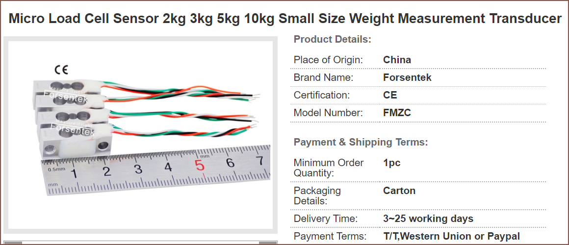
[8:45] One of the smallest load cells I found on the internet:
There was a model on GrabCAD. For all these simulations, I'm using 10N.
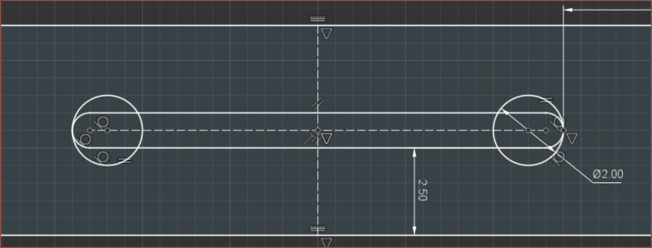
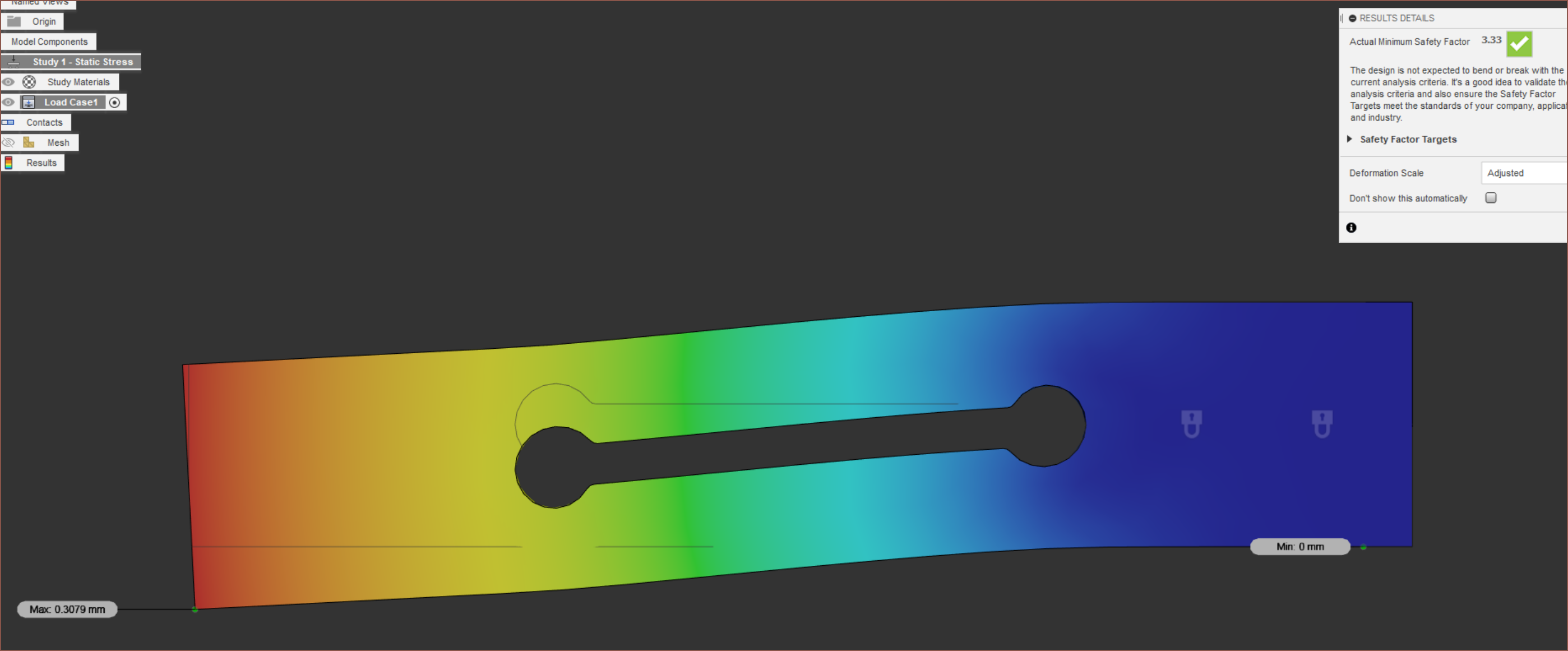
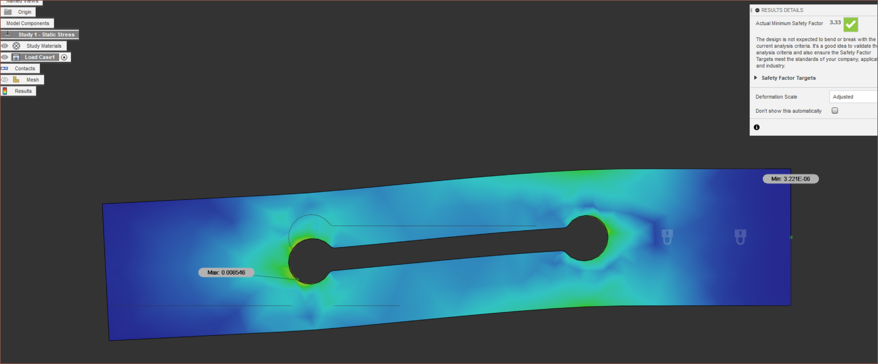
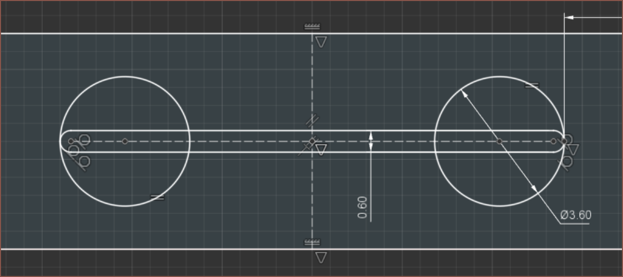
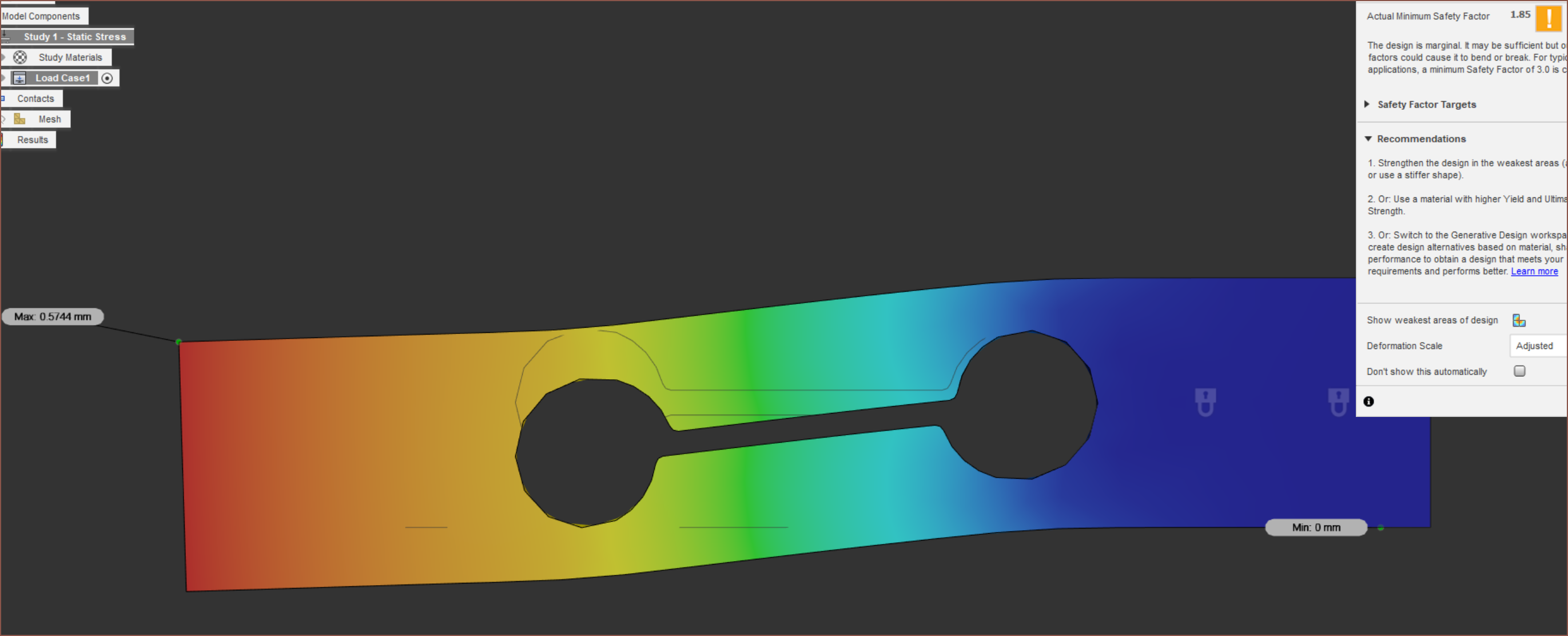
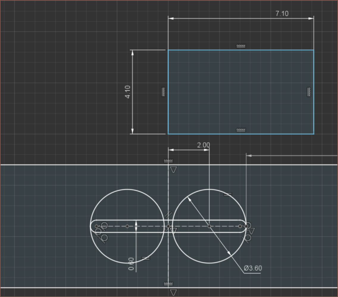
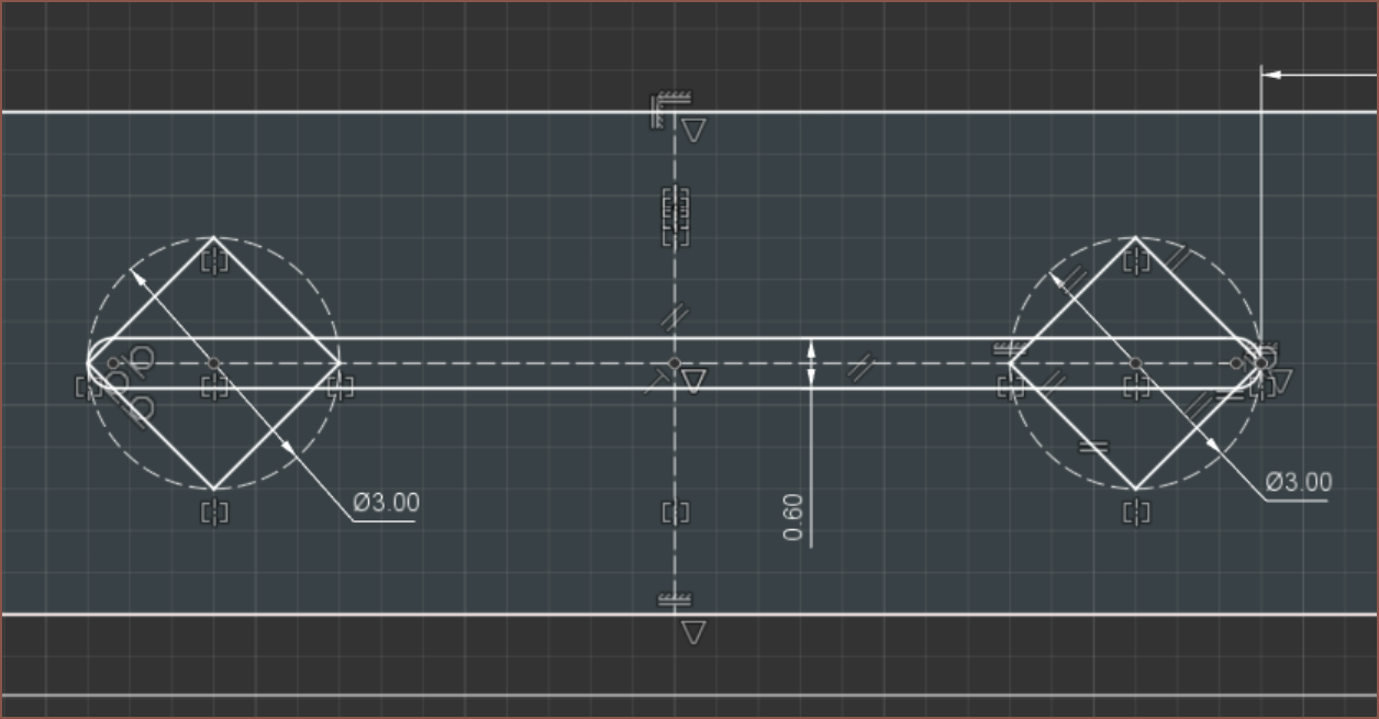
I then went and designed a 4.25x30x6mm load cell for 7.1x4.1mm strain guages. I used the PET material in Fusion360.
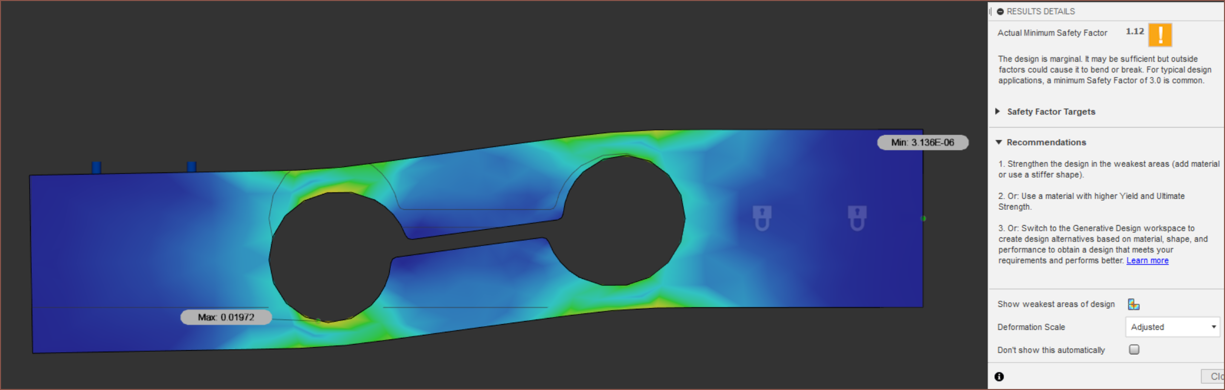
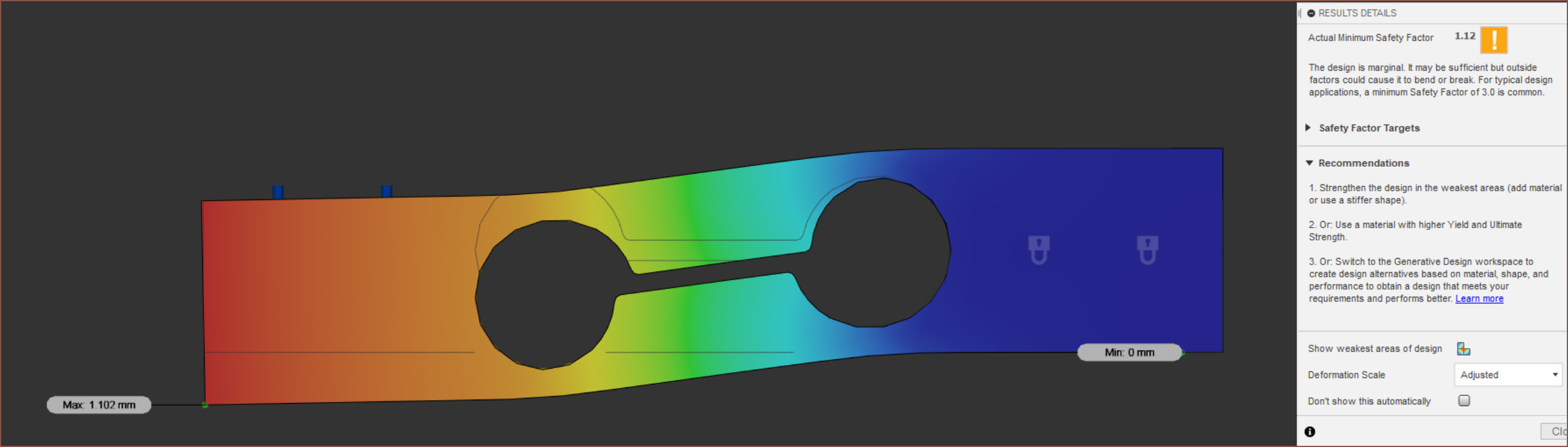
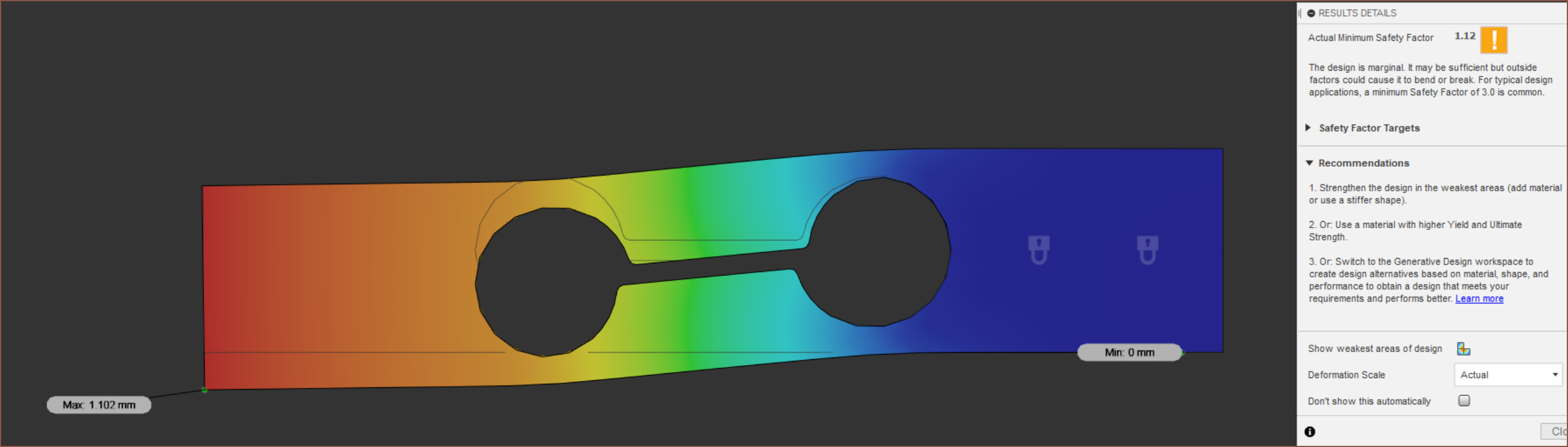
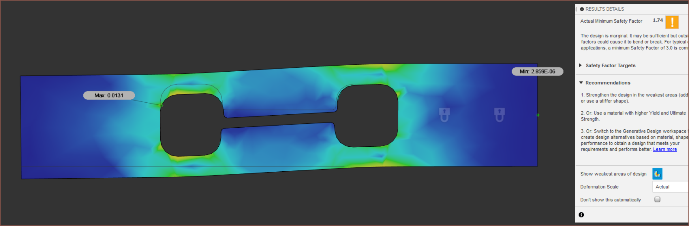
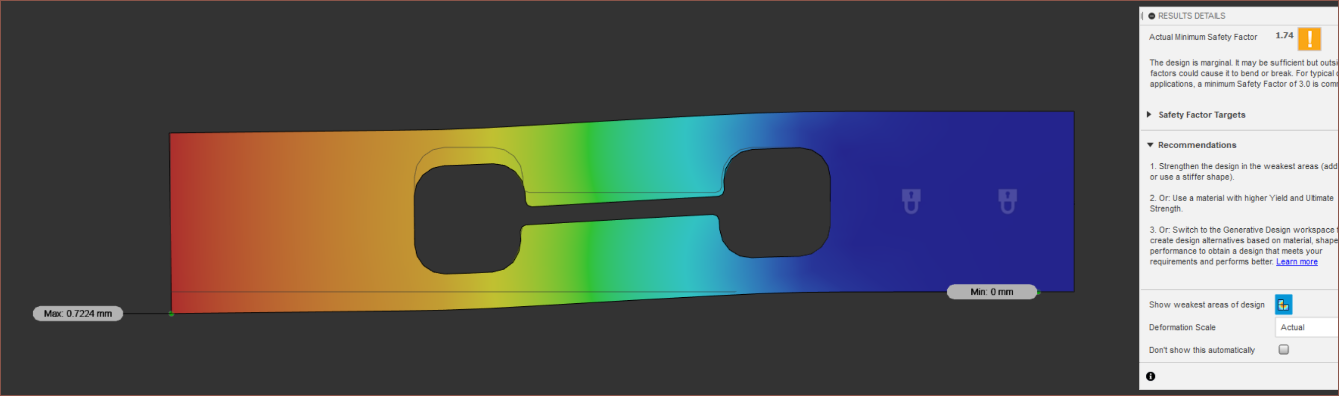
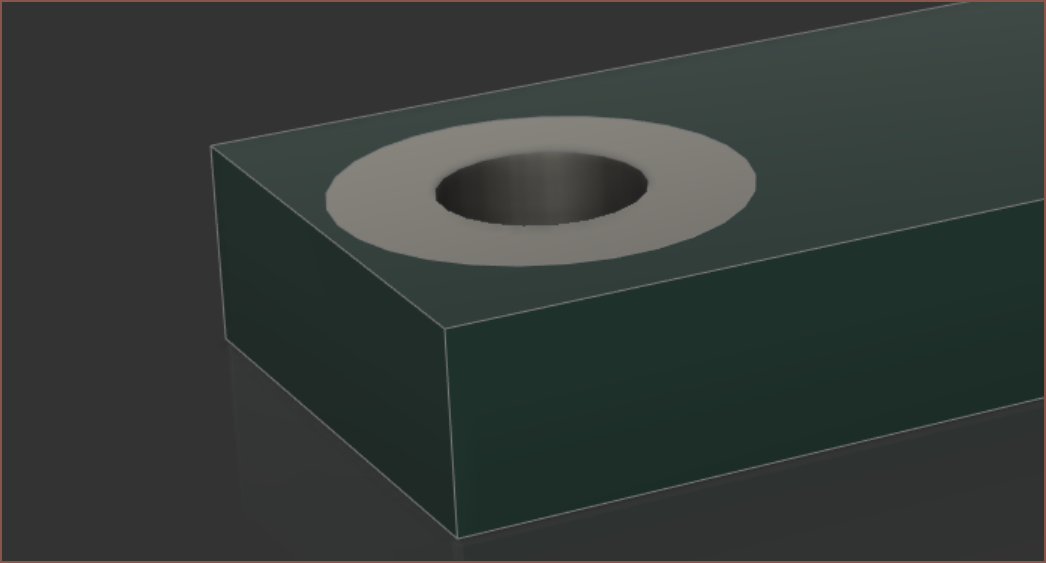
 First attempt was with a 2mm slot. The aluminium cell had 6.3 safety factor and I think this one was somewhere in the 3.X range.
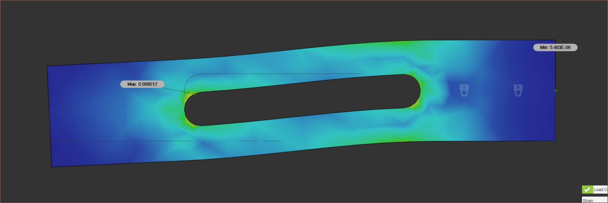
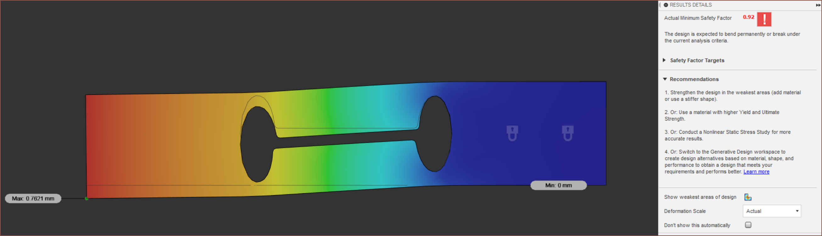
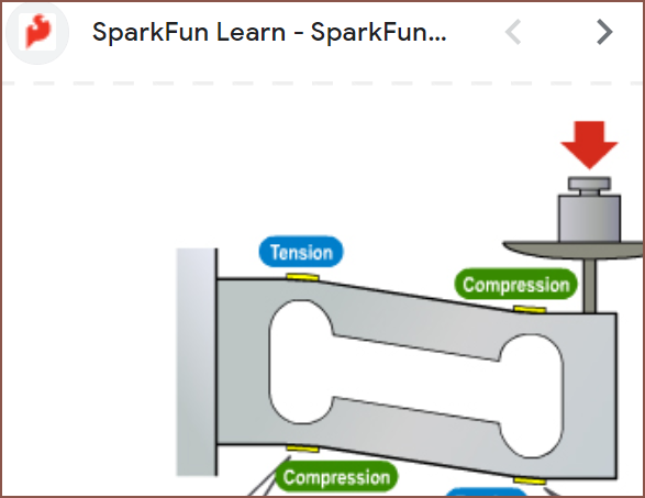
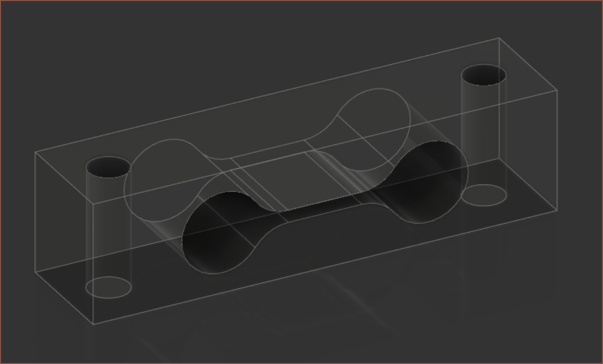
Trying a more bone-like shape just made things worse:
What if I keep the circles at 2mm and make the slot thinner?
Remove the circles and leave the slot:
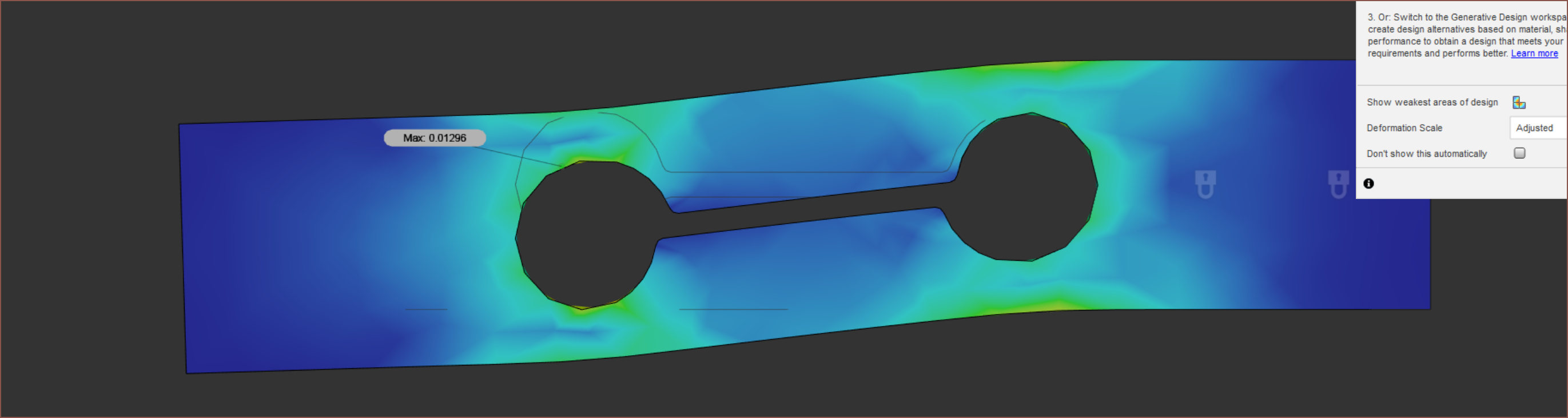
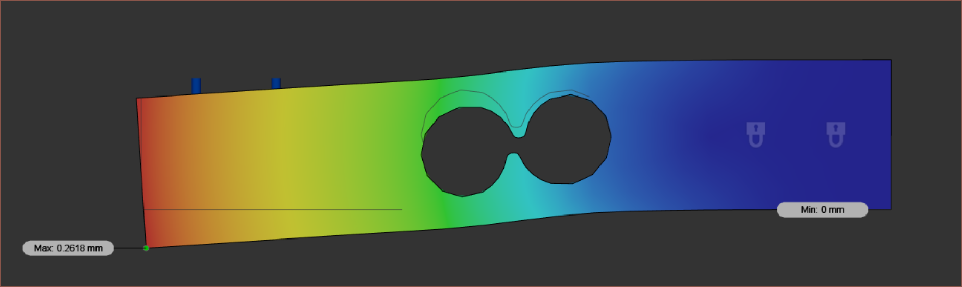
Displacement's getting better, but I'm not getting much bending on one side.
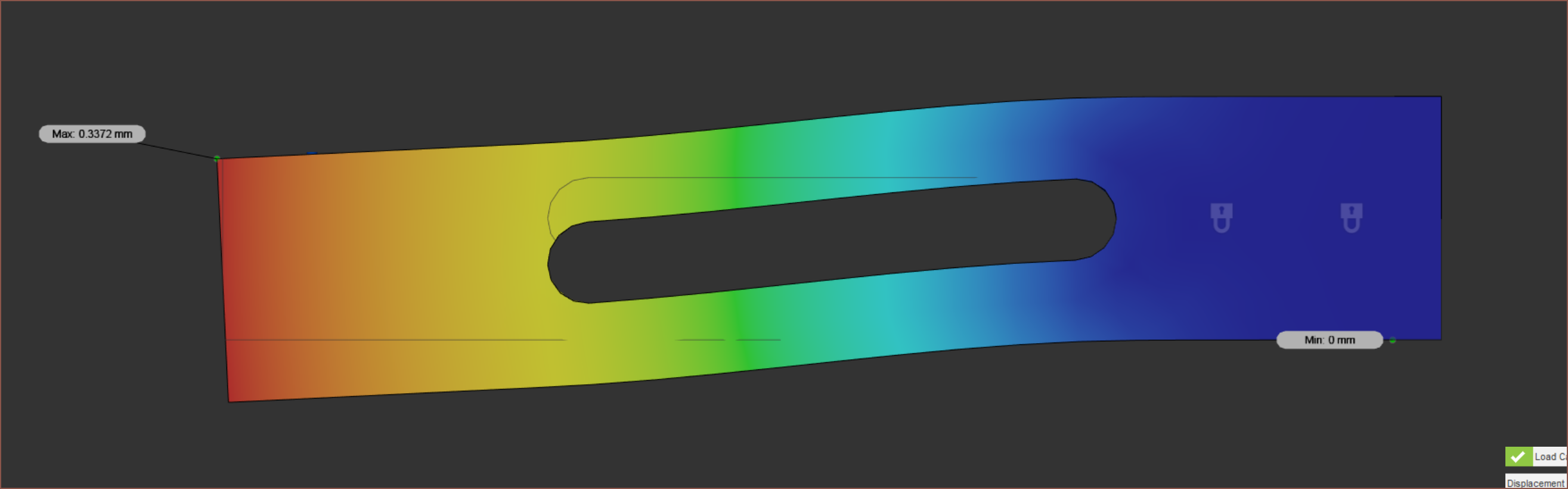
Yeah if I look back at the aluminium, the left side is all orange by the time it goes past the circle. What if there's just a circle on that side?
That didn't seem to do much.
Better deformation but worse safety factor and displacement.
I know. What if I have the strain guages face such that the solder pads are pointing towards the ends of the beam instead of the centre?
 This is just a rough estimate since there's apparently not a single strain guage CAD model on GrabCAD.
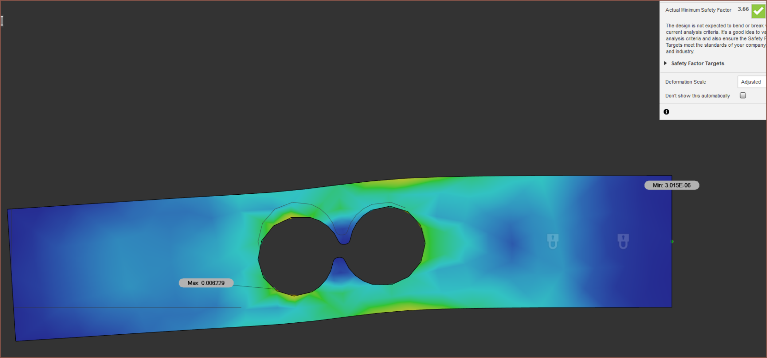
 Hmm still problematic on the left side.
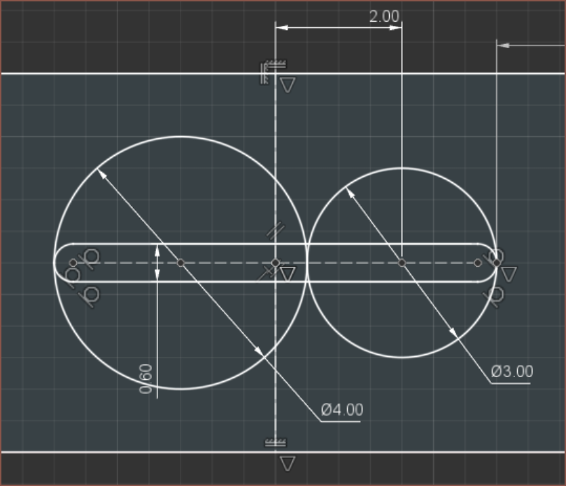
Nope.
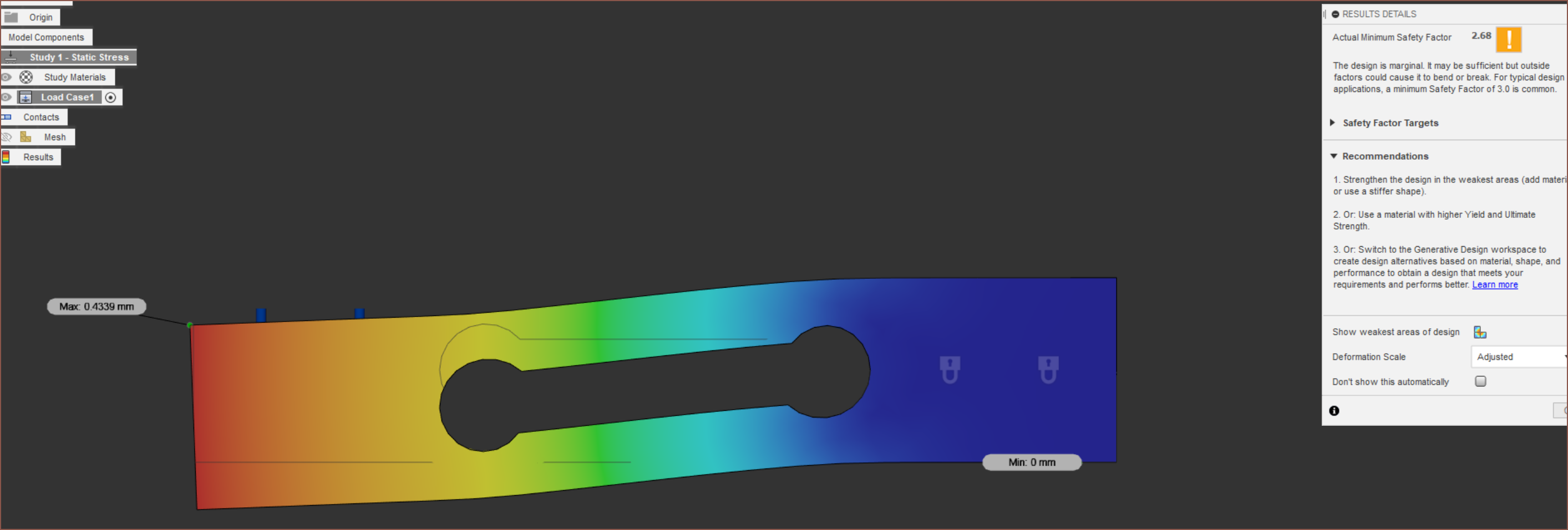
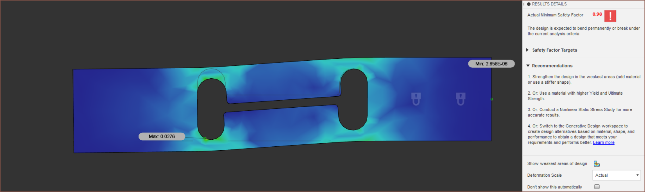
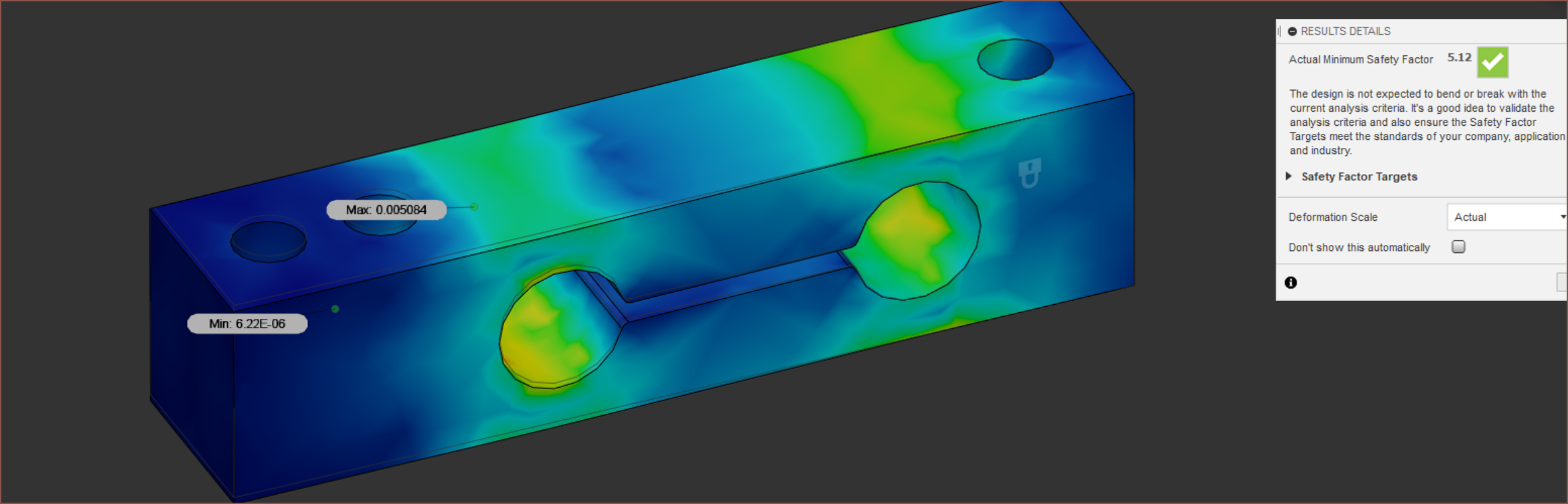
 Getting there, but the safety factor is questionable.
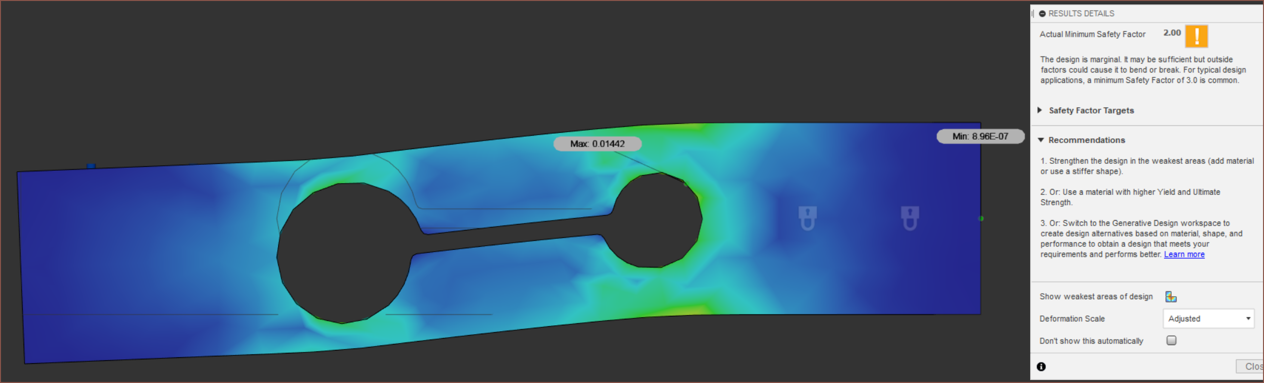
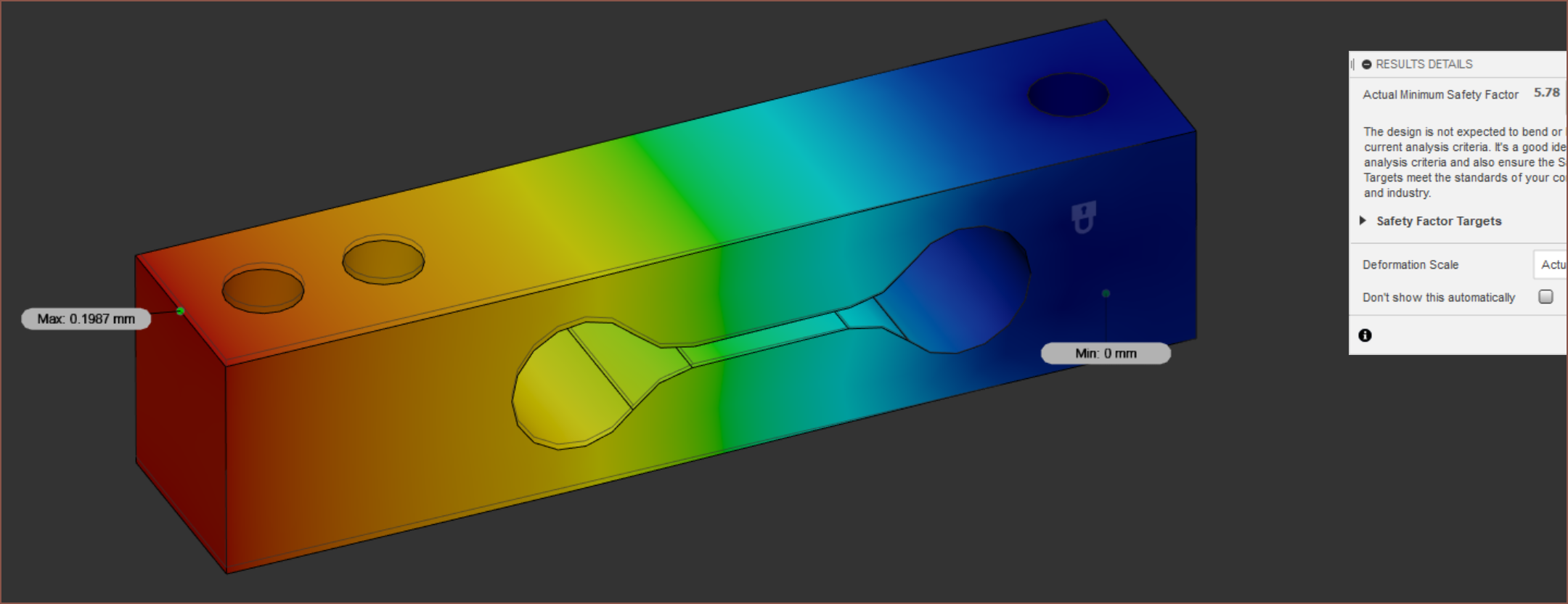
What if diamonds were used?
Pass.
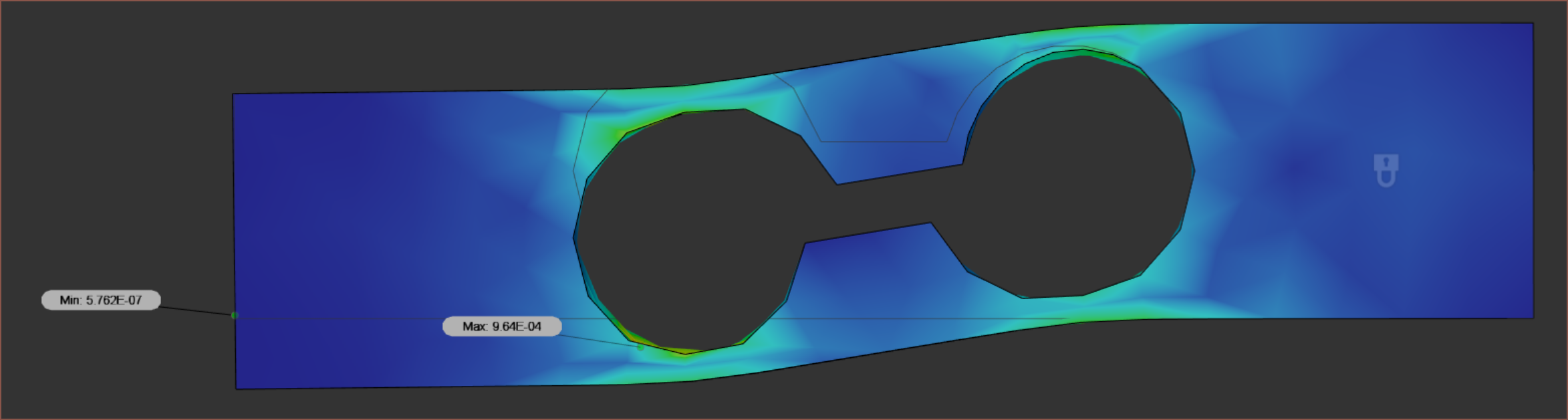
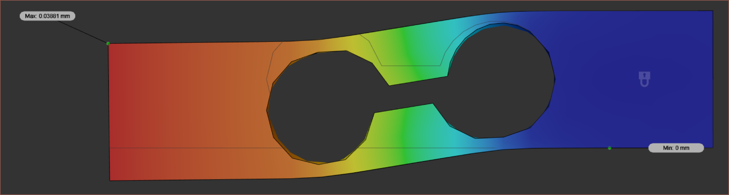
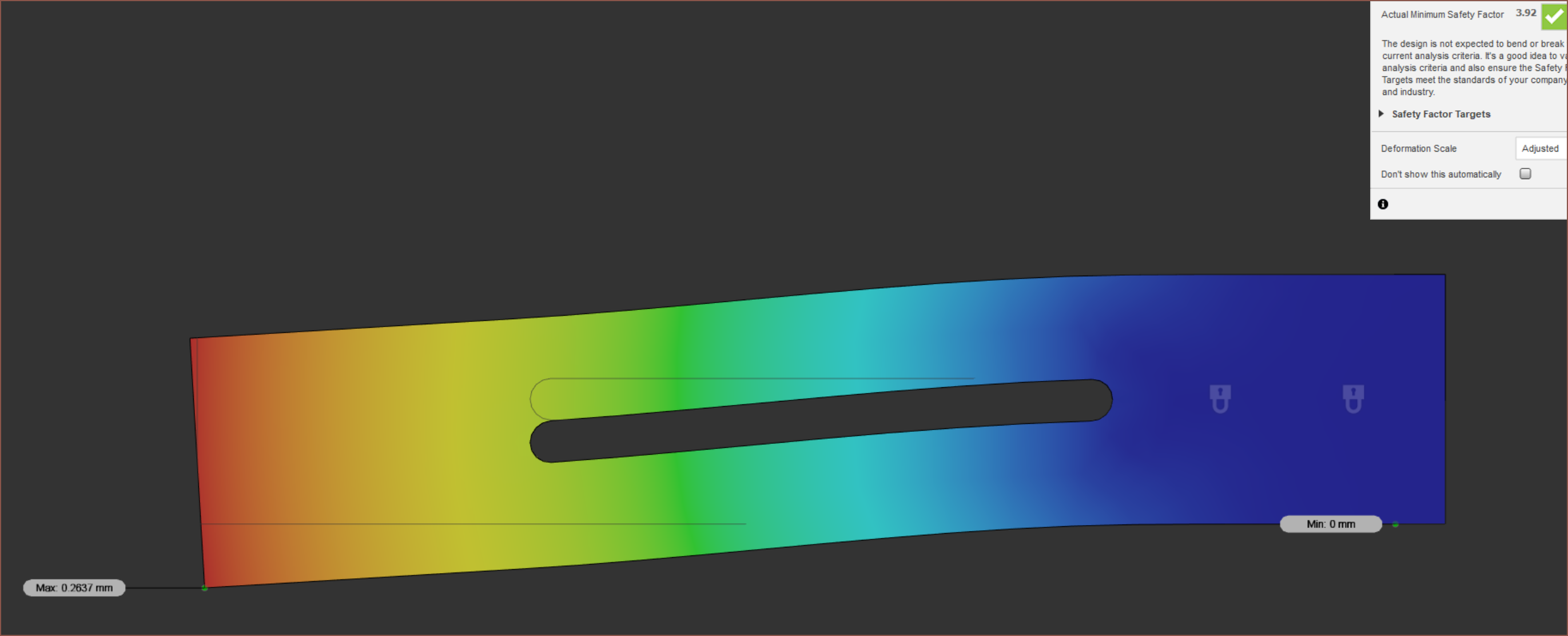
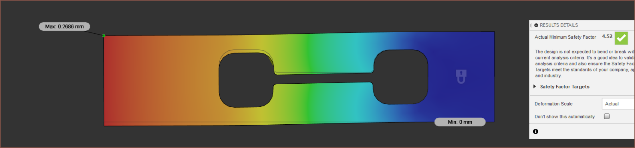
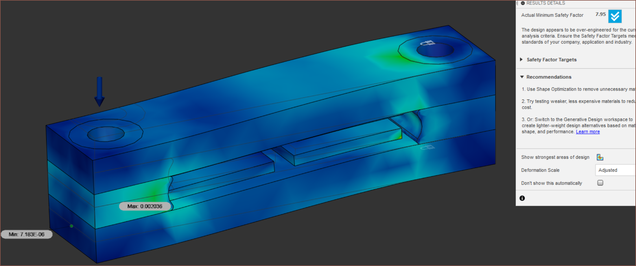
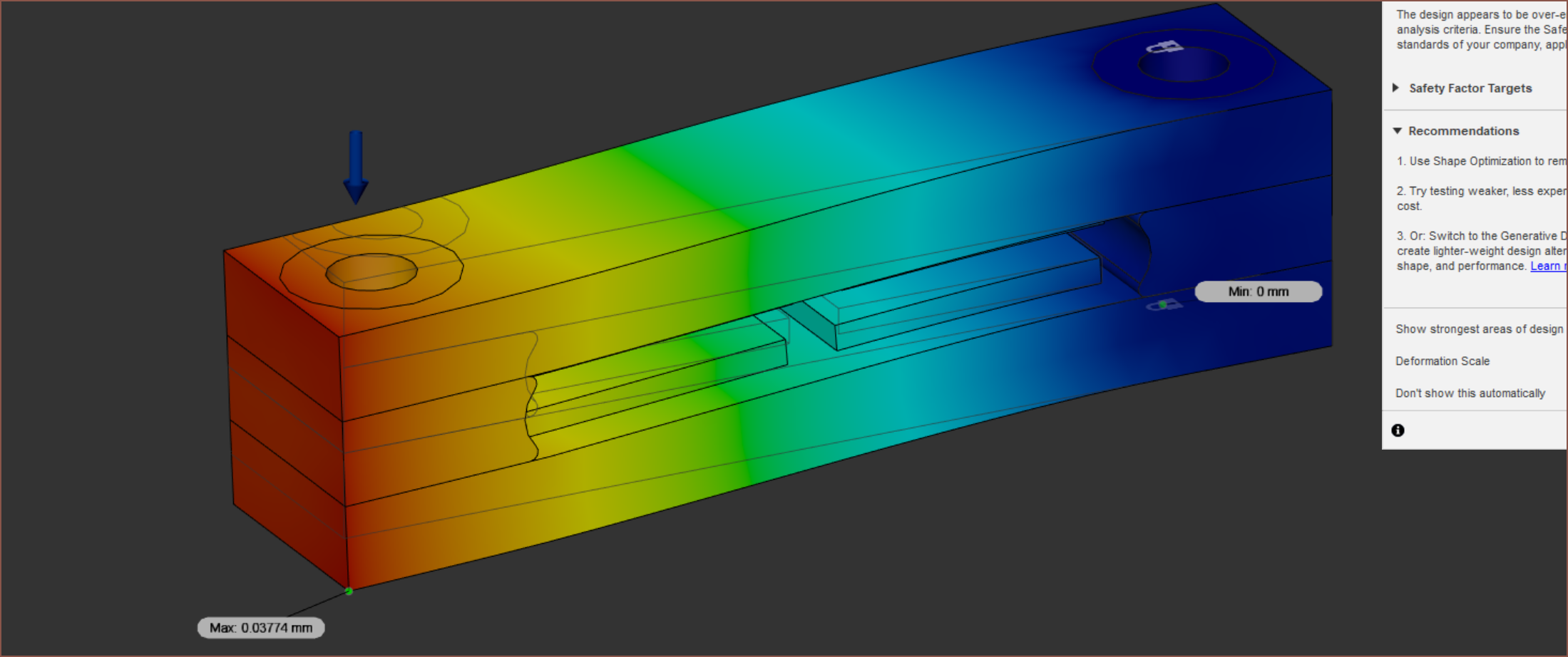
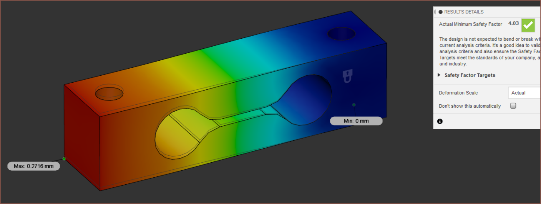
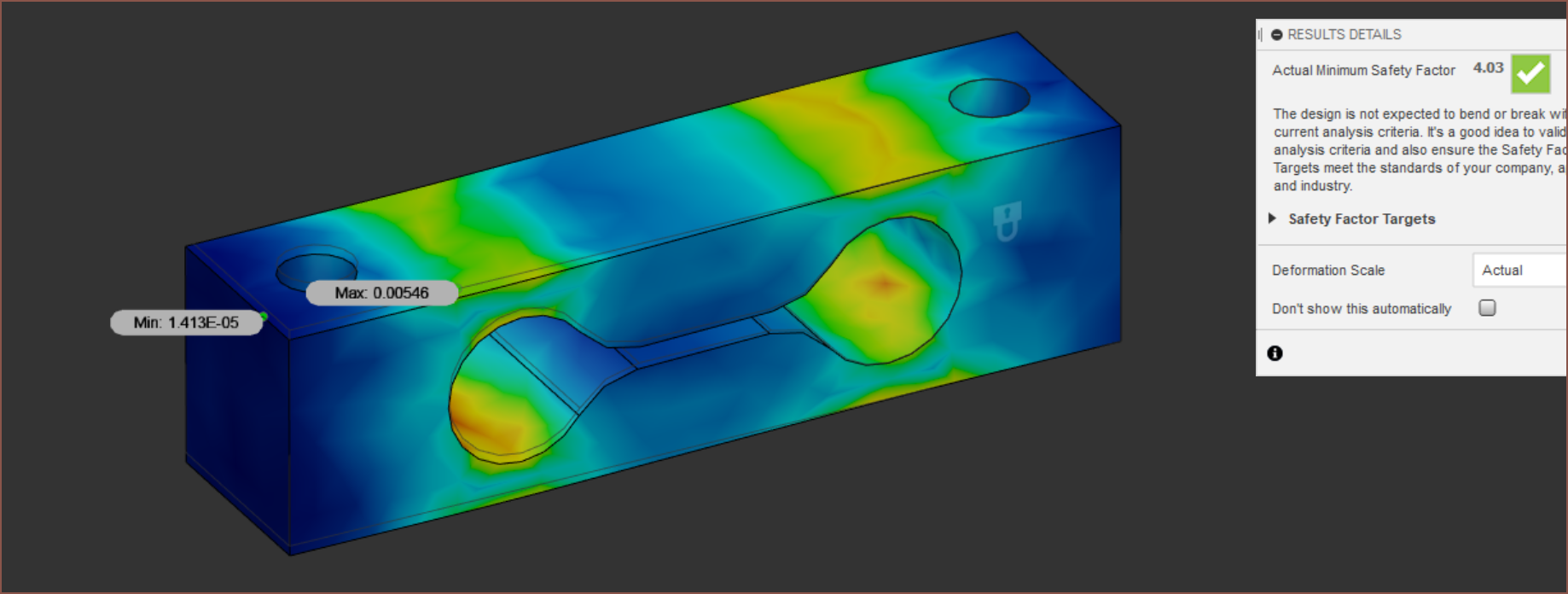
Ok 0.8mm walls on those circles gives the desired strain points. The safety factor is through the floor though, and the displacement is so bad that the "adjusted" deformation isn't that much worse than the "actual".
 Wow ovals are really bad, relatively speaking.
Squares might be going places though. These are 2mm squares with 1.2mm walls and 1mm fillets.
 Again, remember that all these are essentially for a 1kg load. I'm expecting the max to be half that.
There's got to be more optimal designs out there on the internet.
 Interesting.
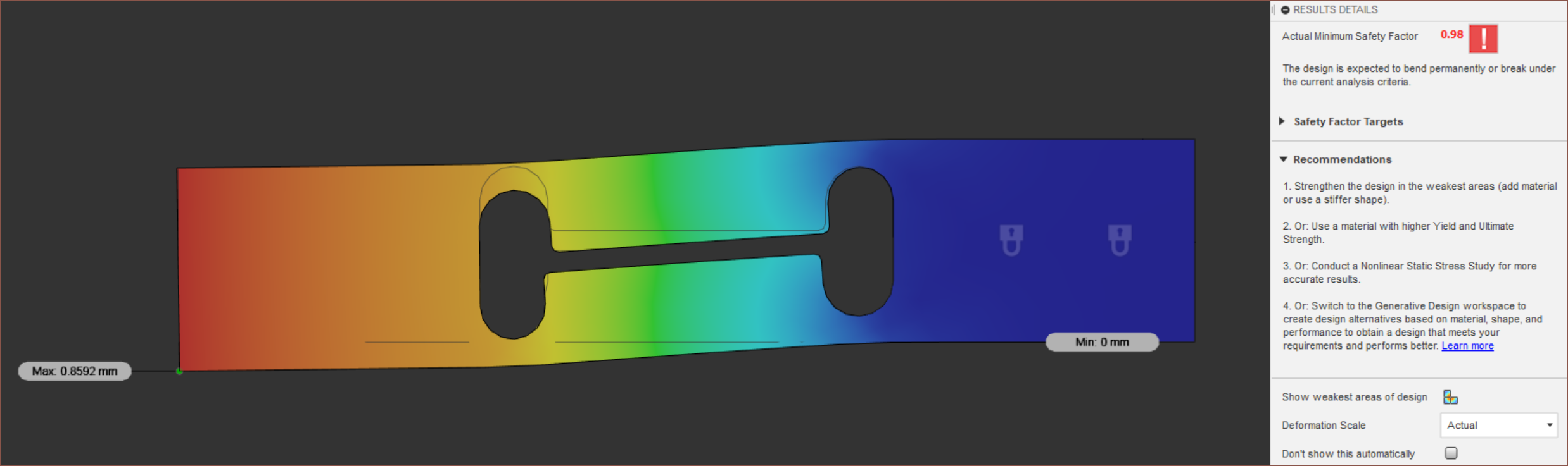
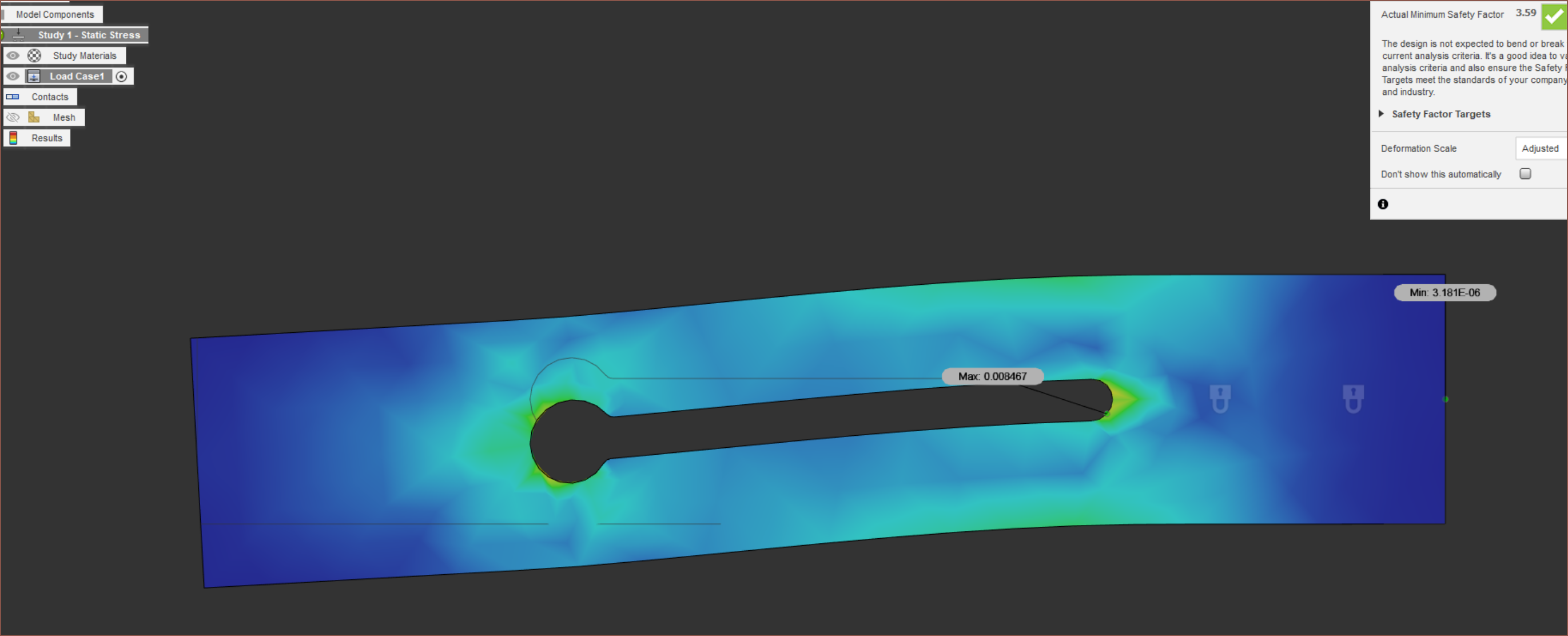
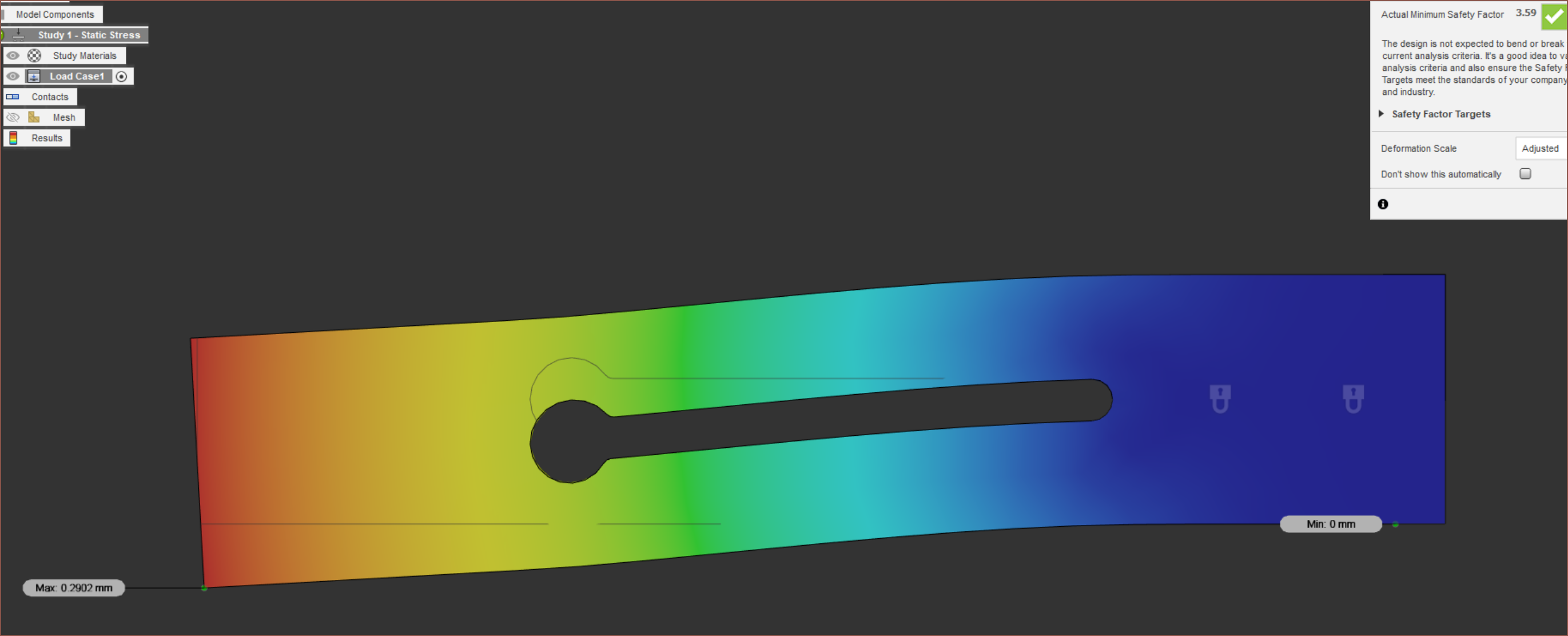
 I'm not all that sold. The thinnest wall is 0.8mm for this simulation.
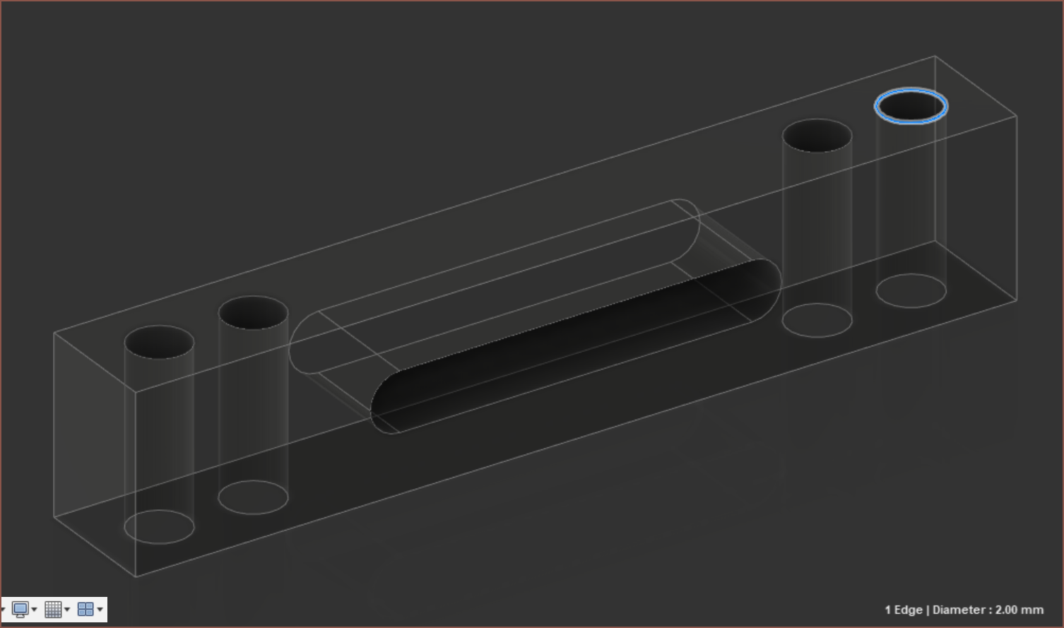
Moving on, once imported into the Tetrinsic assembly, the 3D printed guage is looking even more problematic:
 Add in the wires for the strain guage and there might not be enough space for everything else. I still have the option of going down to 1 bolt per side to reclaim back some space.
Ok this is what I've got:
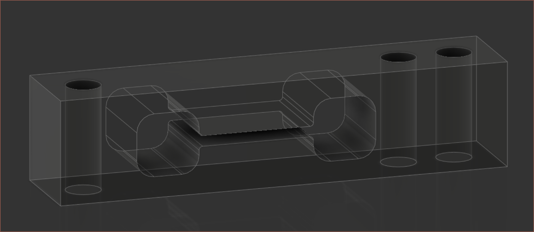 I've increased the thickness to 5.5mm, removed one of the two case mounting holes and now the length is 25.8mm.
 4.9N (500g) simulation:
 I guess this will have to do. I could always increase the fillet 1->1.5mm to see the difference.
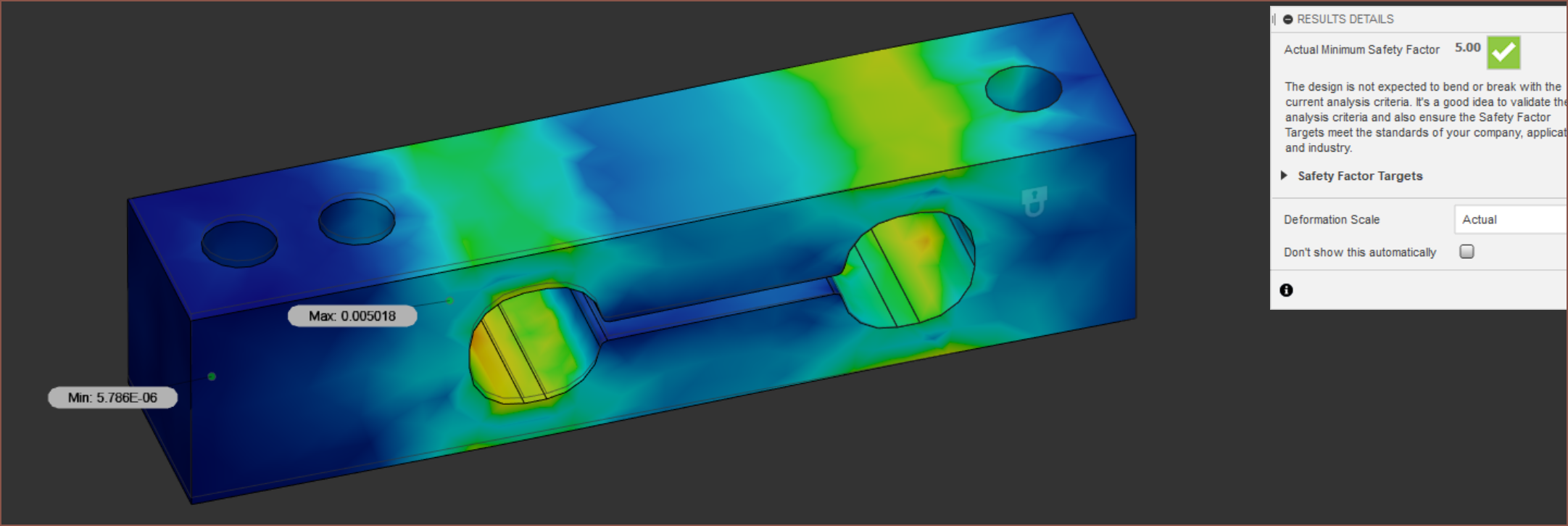
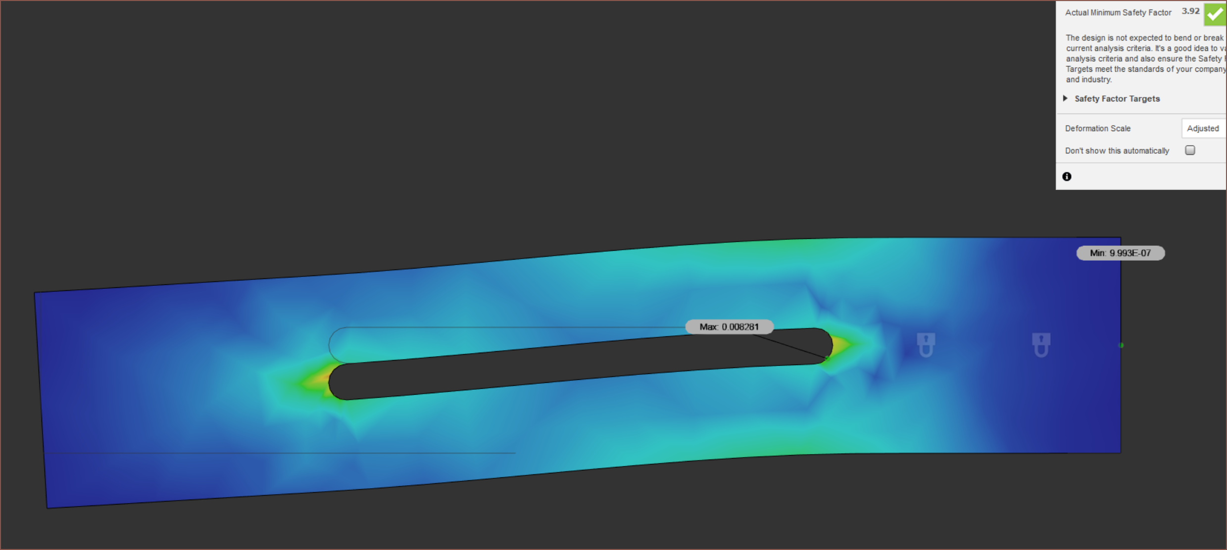
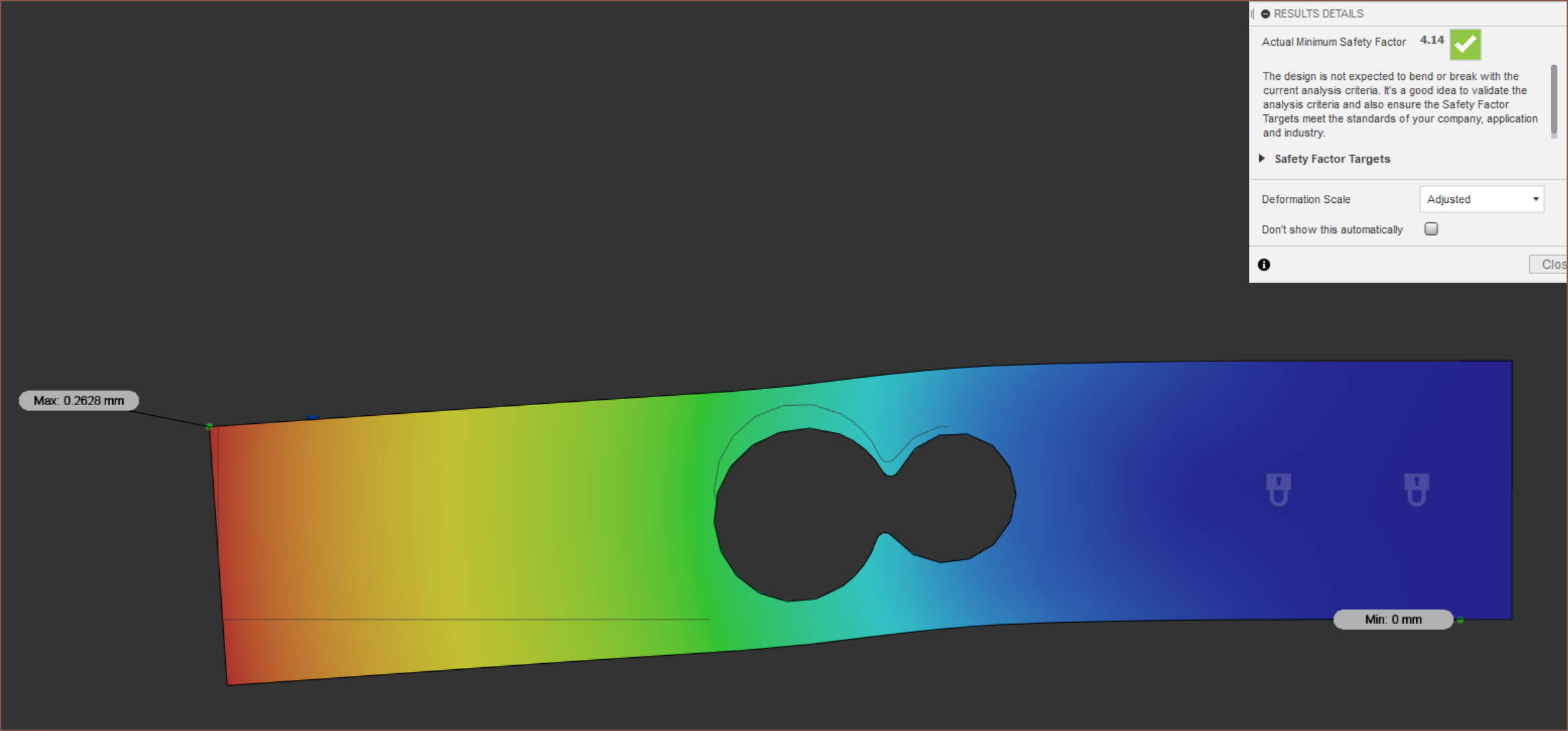
 That does seem to improve things. Full circular?
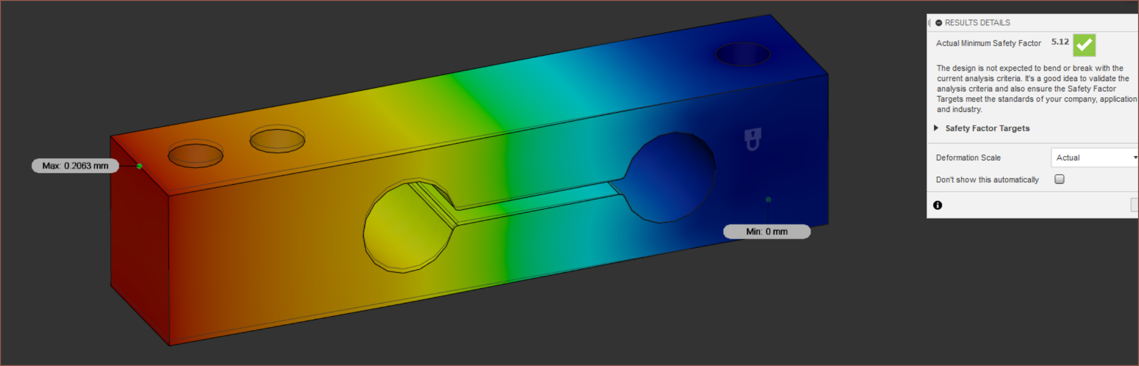
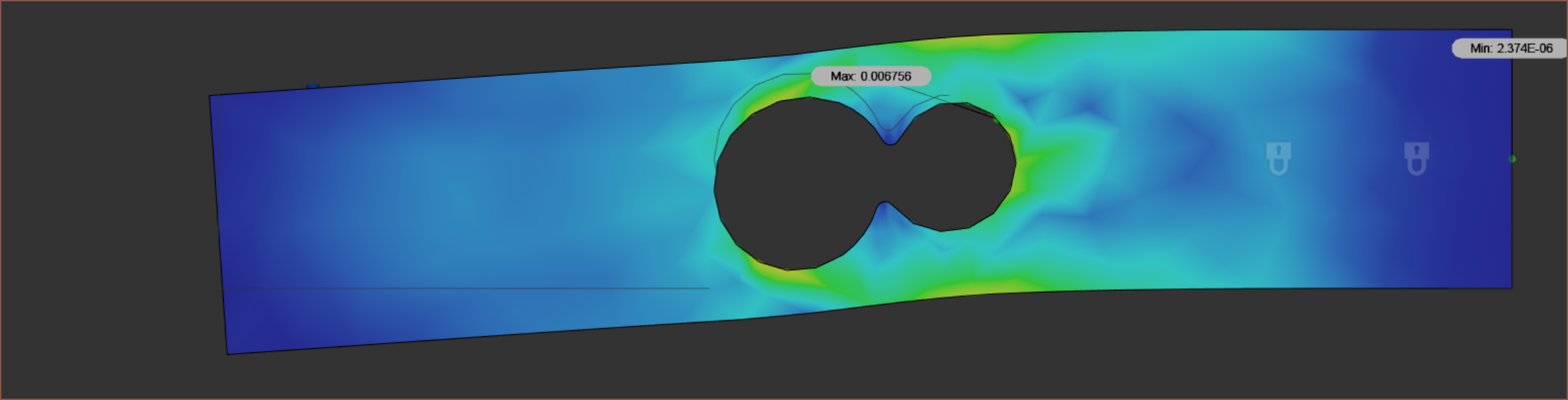
 Hmmm. Larger internal fillets 0.2->2mm?
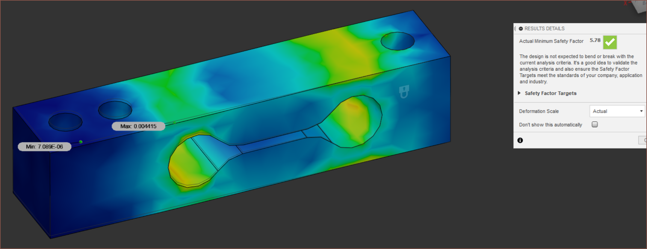
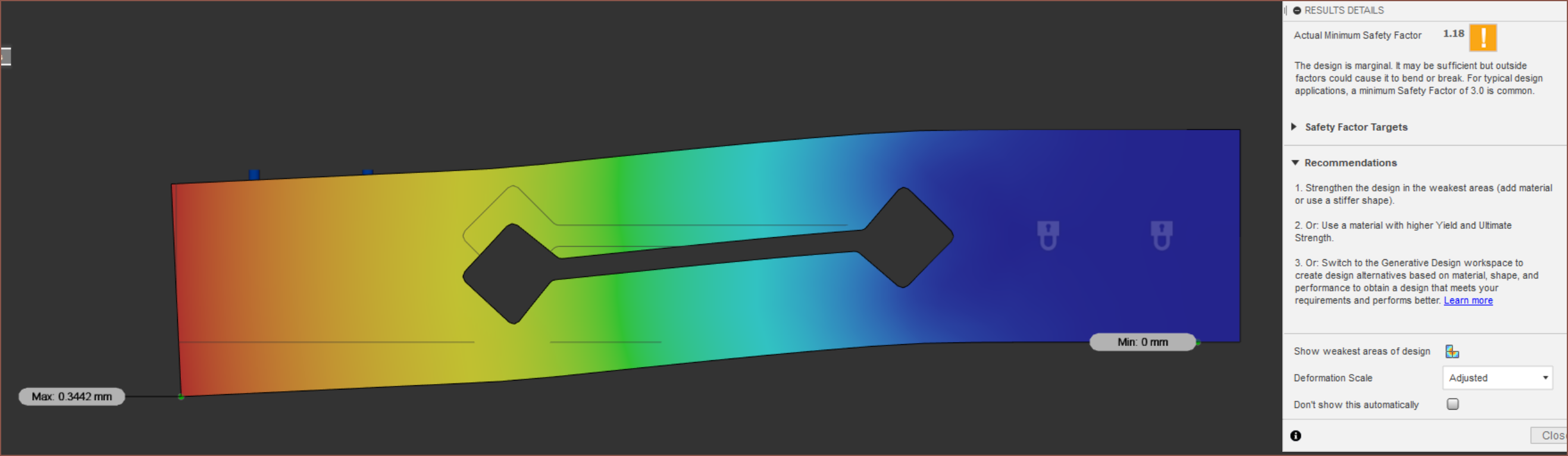
 Okay... perhaps I'd now have margain to go down to 0.9mm minimum thickness walls?
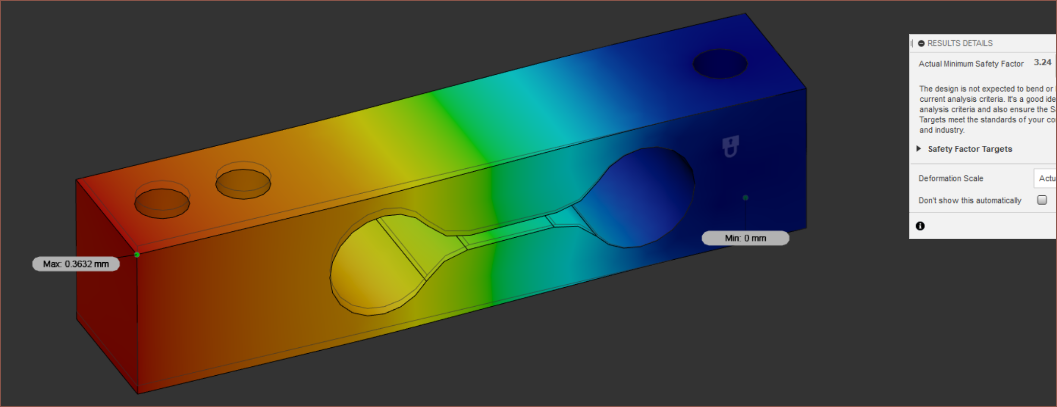
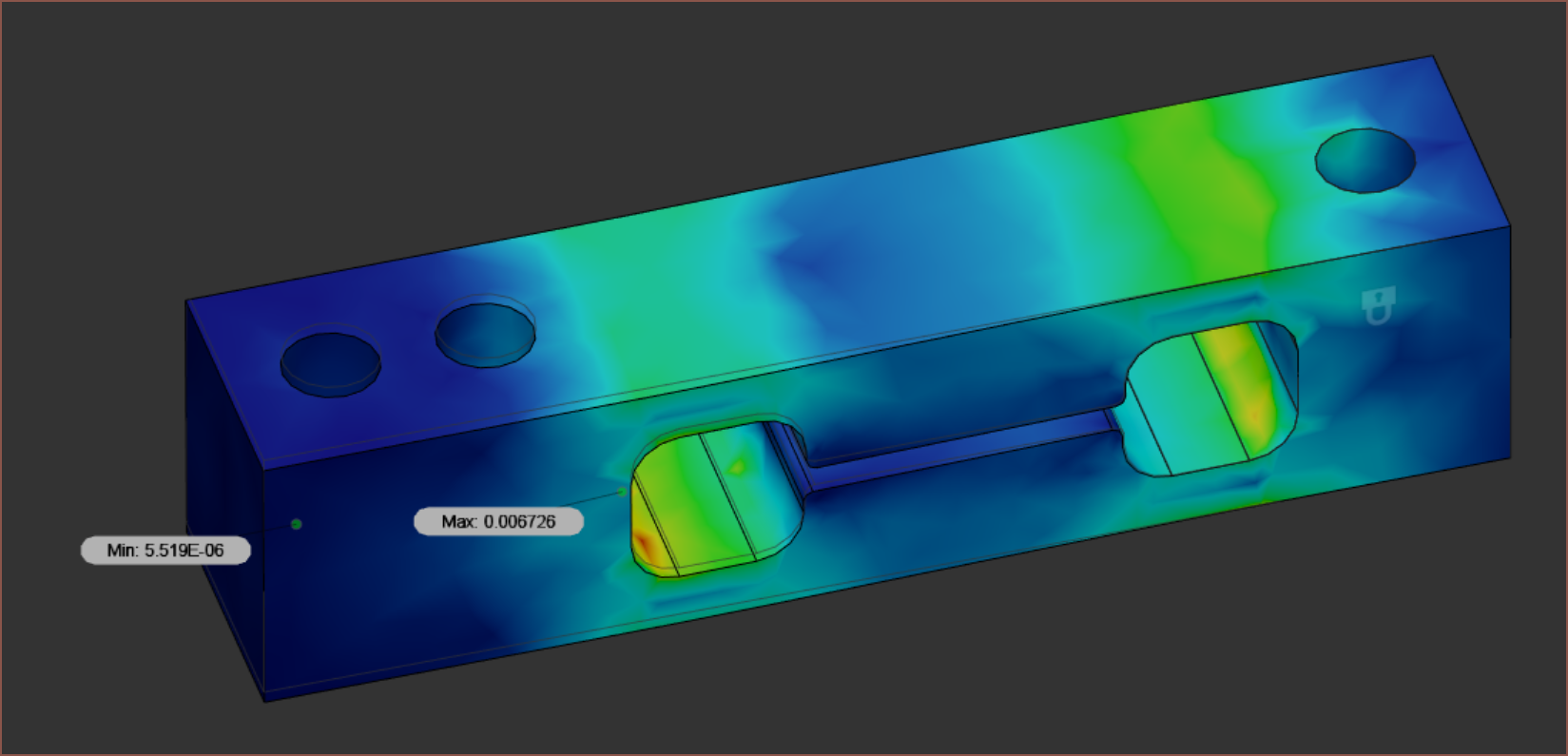
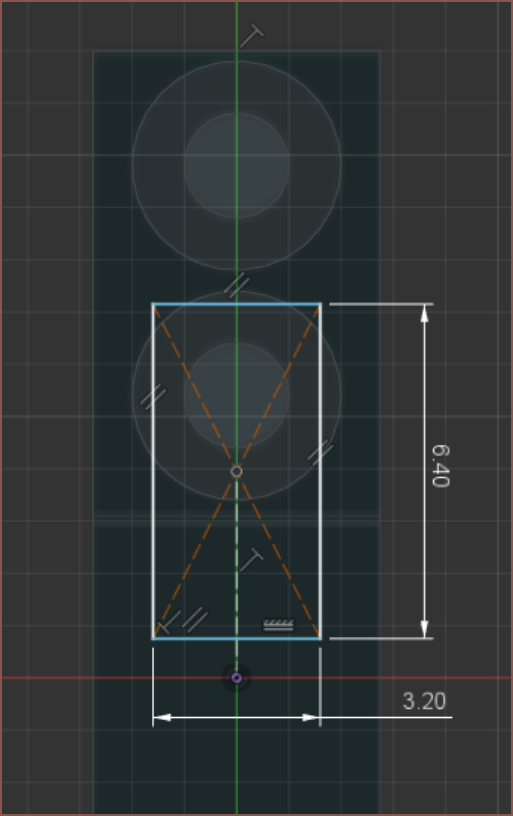
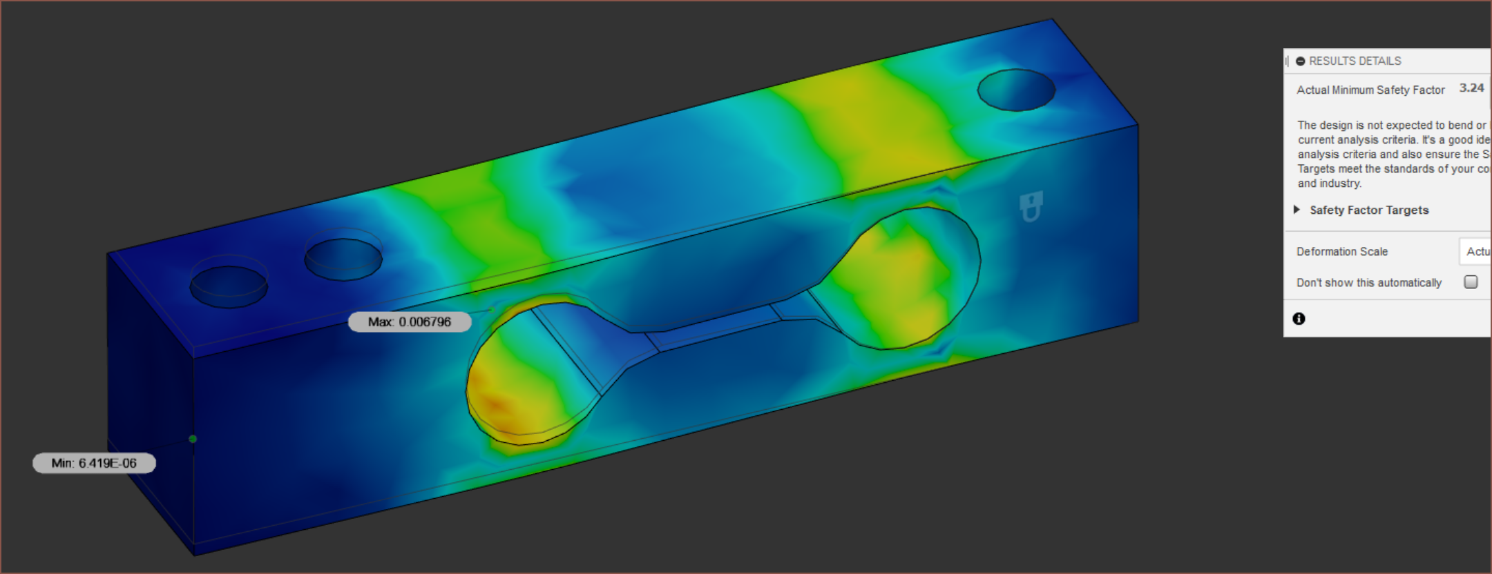 The safety factor takes a hit but it does seem that the PCB mount side (the side with 2 mounting holes) has a more even strain. The length of the cell increases to 26.4mm aswell, and it's not like I even have that kind of space.
 I need enough space for the magnet embedded sprocket. I may be forced to go down to only 2 mounting holes like the aluminium load cell. Alternatively, the total length could be increased to accomodate.
 This is a 2mm overal increase.
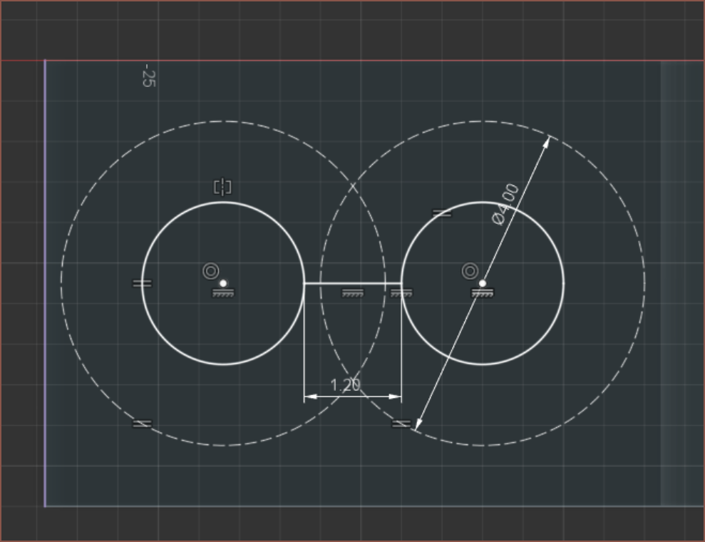 Ah. I forgot about the size of the M2 bolt caps. Adjusting the spacing and increasing the minimum load cell bone wall thickness to 1mm, I get a length of 27.6mm
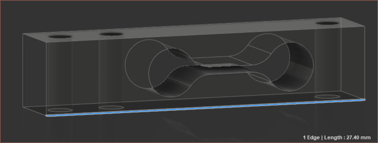
[10 minutes later] Ok. I've thought about it and it seems I have a simple yet inescapable choice. The total length needs to be longer or I need to pay more for shorter strain guages.
[5 minutes later] Or is there a third option? There's been a 3D printer probe sensor that uses SMD resistors and the Smartknob View project recently incorporated the findings into their PCB.
[Some modelling time later]
 Mng. It seems that getting 2 mounting holes is still unapologetically not happening. Lets just move on and simulate:
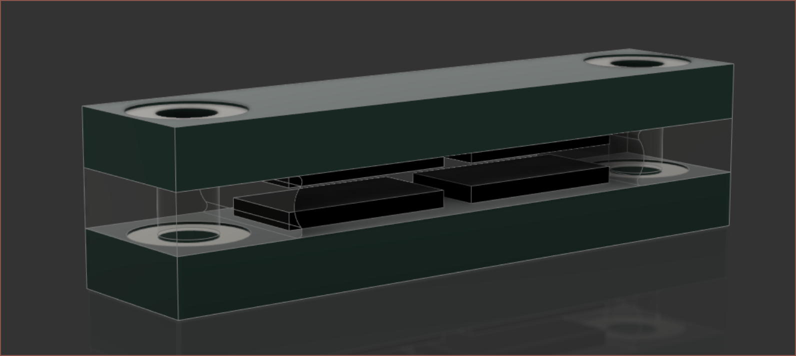 2mm PCB, PET spacers and 2512 resistors.
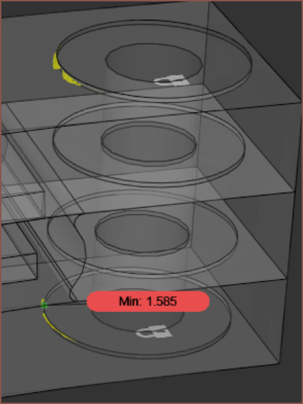
Let me simplify out those cuts...
 Done.
Done.Results:
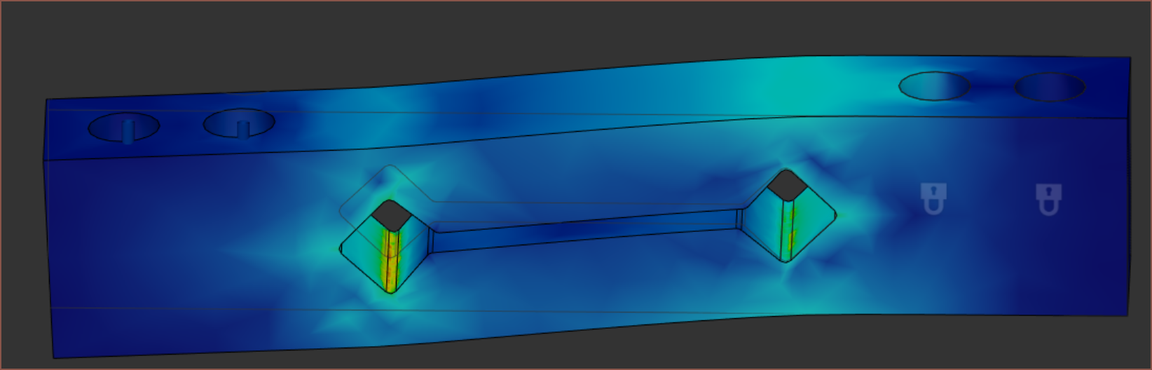
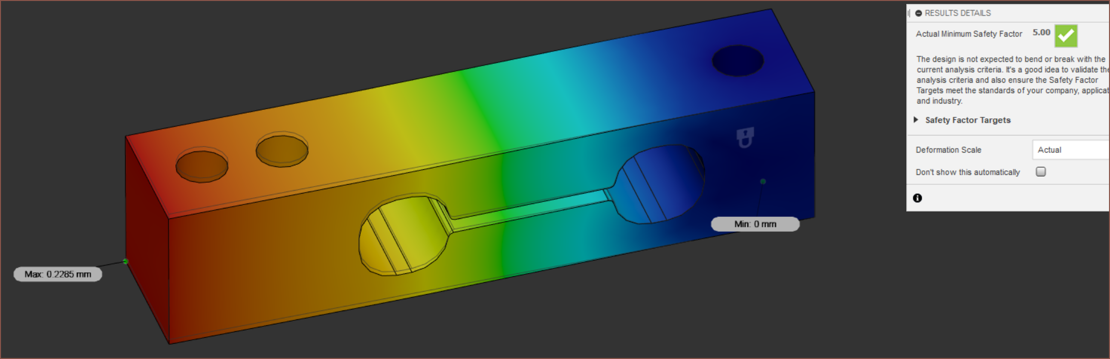
 Great safety factor and max displacement, but the flex is in the wrong places.
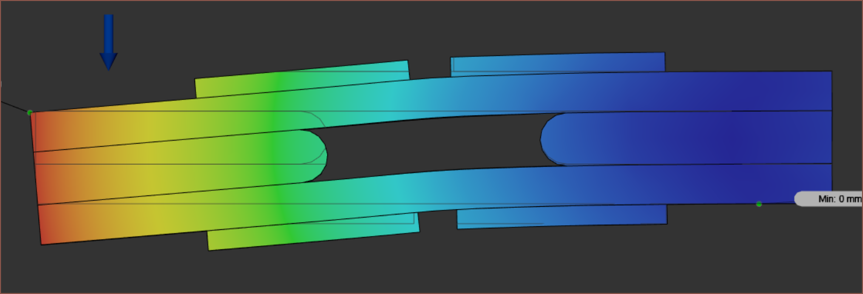 Oh my!
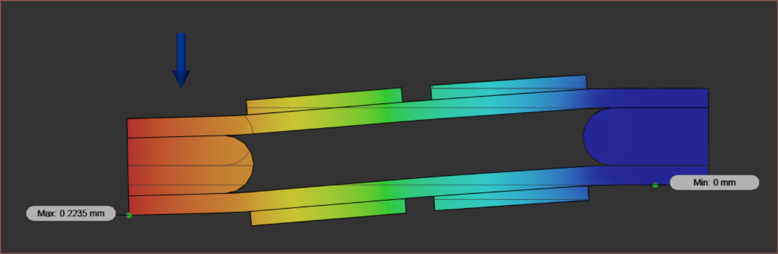 okay...
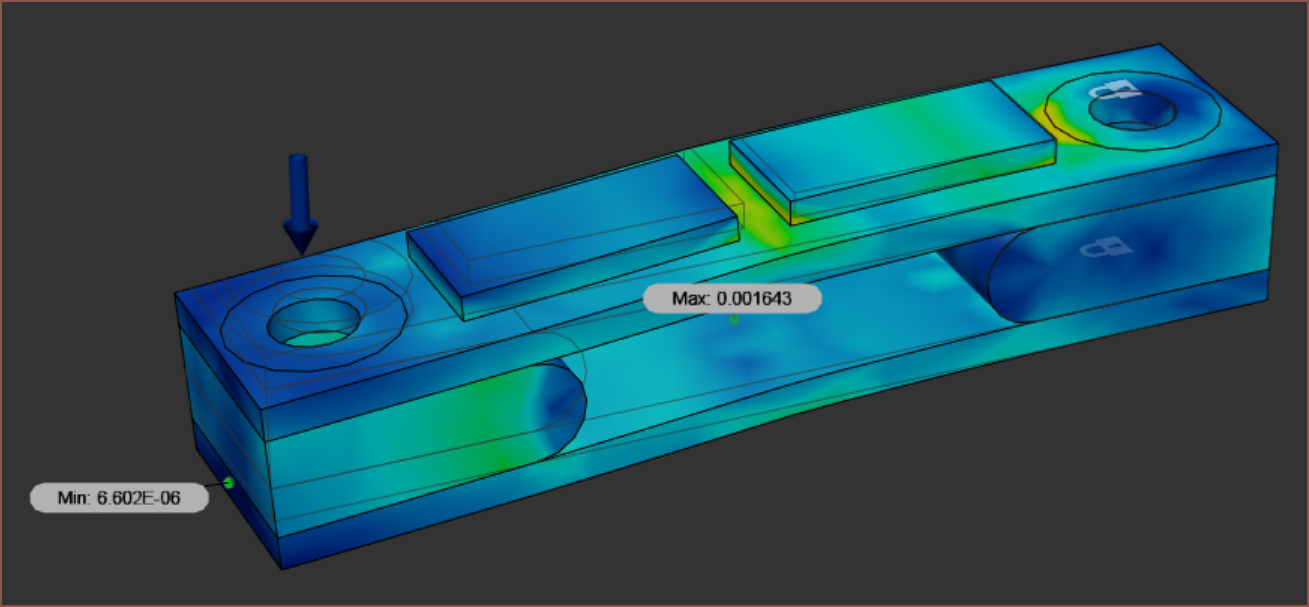 It would appear that the resistors are essentially adding stiffness in the area where I want to flex. Perhaps I need to adjust the contacts to reflect that the resistor isn't attached across the whole length and just at the solder ends.
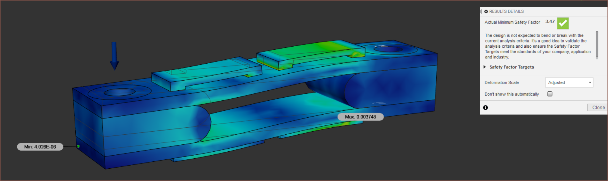 Okay alright. Not sure if it's good enough for science though. I should note that I'm expecting each of the 7+ actuation levels of Tetent to be 8g spacing, with a +/-2g crossover haptic. I'm not using this for a binary solution like Smartknob.
In any case, because of the mounting hole issue, I still haven't escaped my simple yet inescapable choice. And it's [16:30] now.
[17:00] The choice I've made is to go down to a single hole on each side and compute a solution to prevent unwanted rotations at another point in time.
4.9N weight simulation:
Discussions
Become a Hackaday.io Member
Create an account to leave a comment. Already have an account? Log In.