 kelvinA
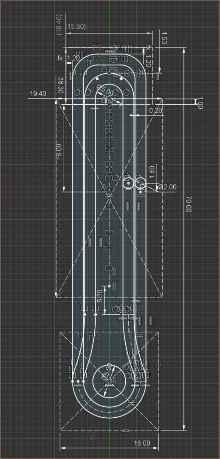
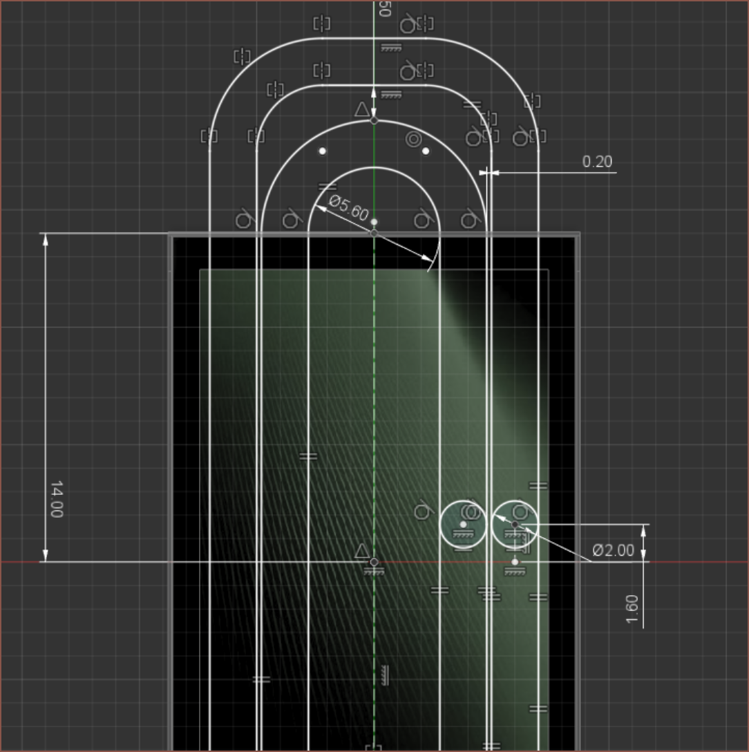 [22:30]I've gotten this far, and I'm already thinking that the thing has to be mounted upside down so that the fingers don't intersect the motor block (opposide end of LCD).
The active area needs to be thin but otherwise rigid, so I'm thinking of using some stainless steel bolts that are smooth other than the ends. I'm having trouble finding that though in stainless steel.
Screen choices
The ball-chain needs to slide on something, and the LCD is an ideal size and thickness, so I might as well keep it in the design. On that thought though, if I'm now able to layer adjacent Tetrinsics due to its thinness, I could actually have an even bigger (but still under £2/ea) LCD. From research with the 1st Gen Tetent, as long as the overlapping sections are under 3mm, a solution is possible. Additionally, with the new TimerSpy design proposal, I think I could have up to 80mm of max length for Tetrinsic. However, bigger screens have more pixels to run though, so perhaps there is reason against such a change.
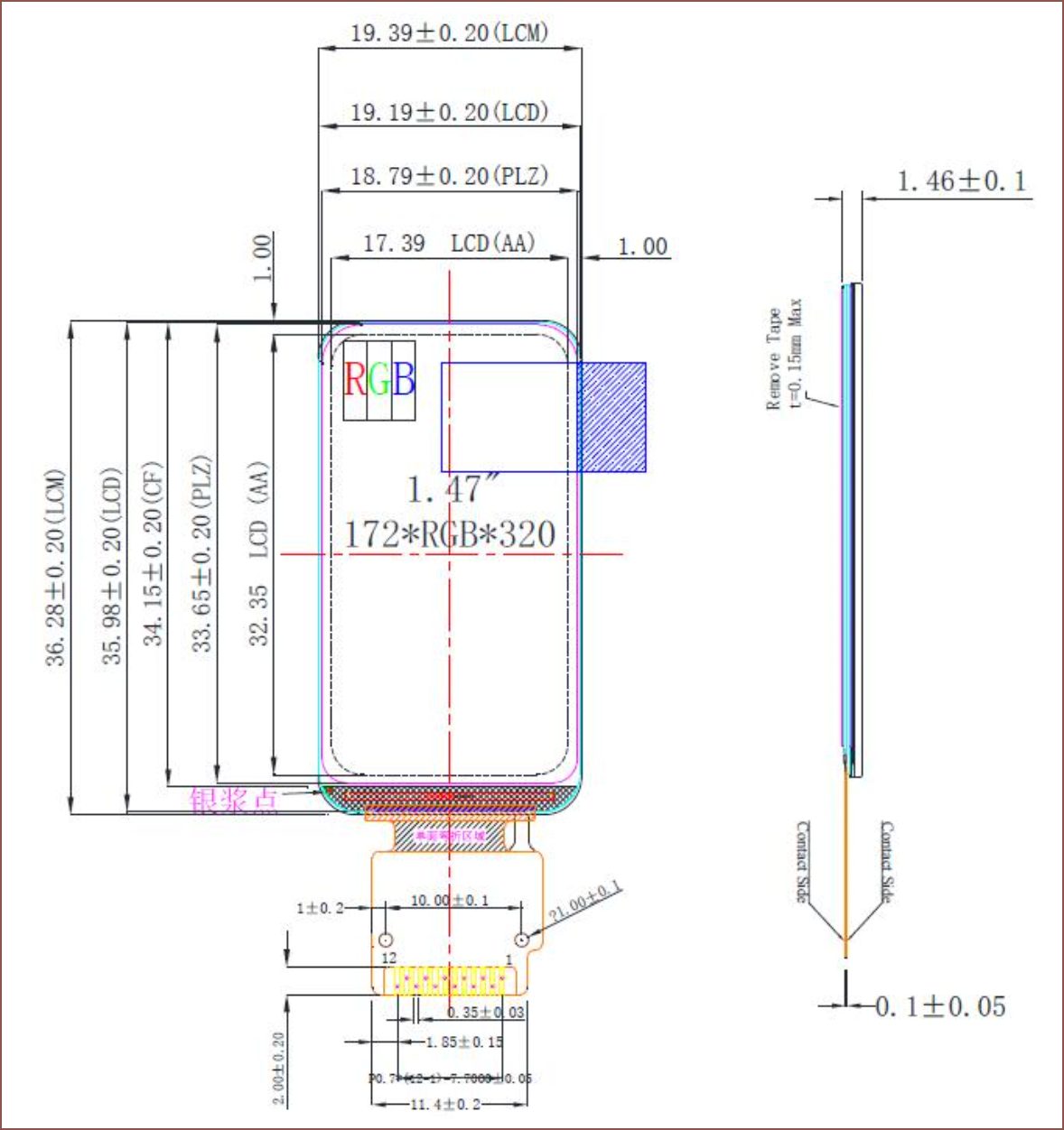
The only candidate I could find is this 1.47" TFT that has rounded corners and a slightly thiner bezel and overall thickness. It still uses the same driver IC so that's nice, and about 70p more than the 1.14".
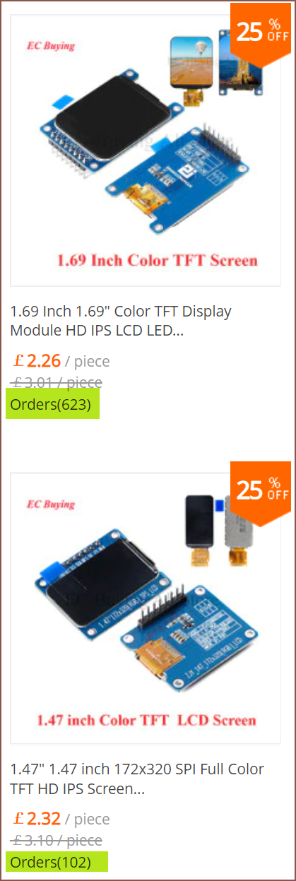
 The increase from 24->32mm could be beneficial from an ergonomics and usability perspective too. Other than the £7 BOM increase, I'm not seeing many drawbacks, and the benefits are a longer active area, a more bezel-less looking screen (the chin is smaller too) and a higher screen to ball-chain ratio. I also wouldn't be suprised if the colours look better on this panel either, since it just overall seems like a more modern one. Oh, and it might look even better if the Tetrinsics are layered, allowing for animations that span across multiple elevations. Other customers also seem to like the slightly larger, rounded edge screens:
I'd likely have to conform and use rounded rectangles instead of filleted chamfers for aesthetic consistency across the design now, but I've otherwise made my simple but escapable choice.
[23:05]
 So this was the idea I had in mind before I determined that the motor needed to be on the side away from the palm. It doesn't look like i'd have the space for a load cell body anyway, and the side m3's I was about to add just made the top box too wide. Since the small top box would be in the position where the Tetrinsics are the closest, it should be as small and thin as possible.
[23:50]
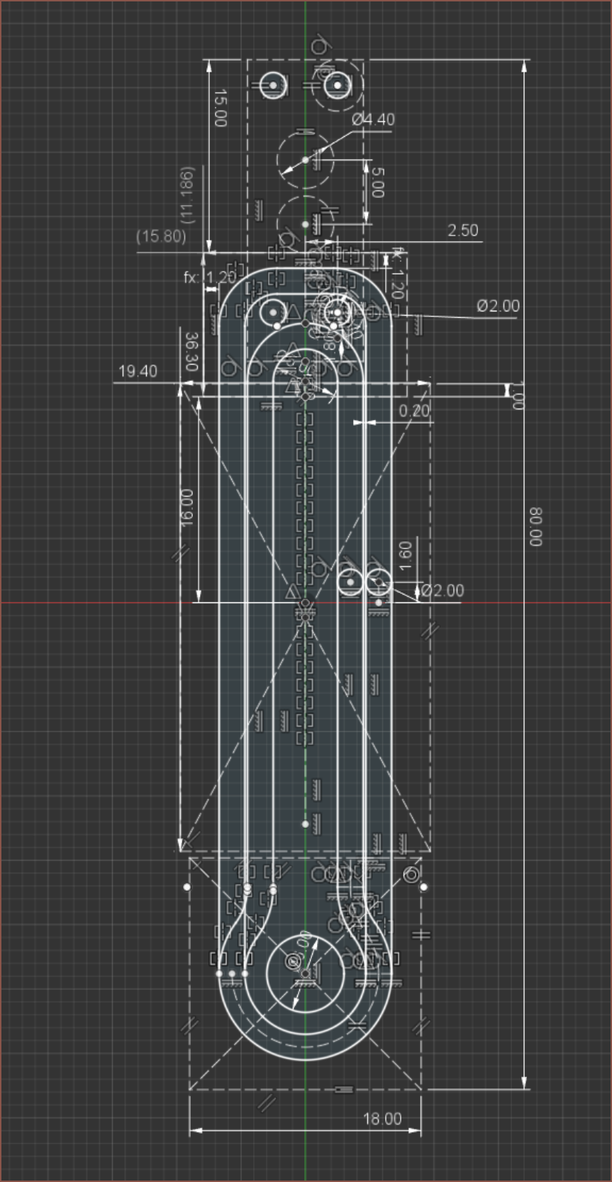 Ok. I've already hit the max allowable total length but this might work. Those 4.4mm circles at the top represent the ends of the cutout for the load cell geometry. The main issue I can see right now is where the load cell connects to the small block. Right now I'm imagining a shape like this:
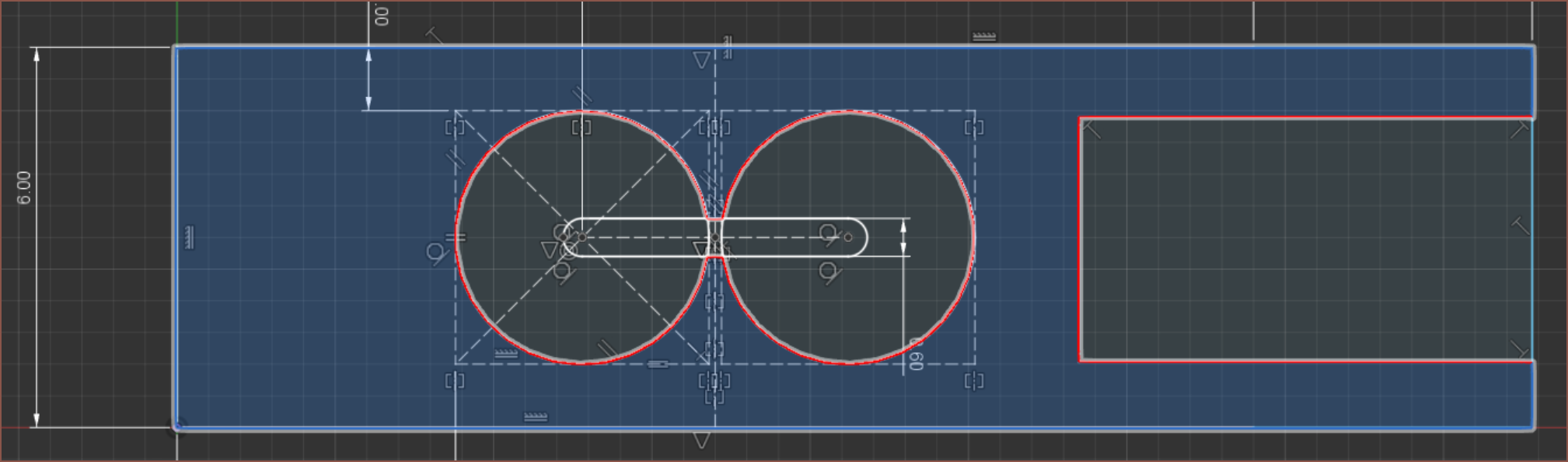
Solution mining... ends, in 28 days.
Discussions
Become a Hackaday.io Member
Create an account to leave a comment. Already have an account? Log In.