 kelvinA
[17:30] Sorry, but the motor sticking out of TestCut is an eyesore. I started looking into drawing up the new PCB, viewing the AS2040 for reference since I found it through EasyEDA and without the header pins, seems close to the target Tetrinsic PCB size. This then lead into considering if I want to solder the LCD directly or use a ribbon cable extension. Then I was wondering if I should include MemoryLCD support too (for TimerSpy) or have something off-the-shelf.
Eventually, this turned into trying to remine for a solution that didn't have the motor sticking out from the top. It doesn't look good in TestCut and I imagine it wouldn't look that great on the back of my hand either for TimerSpy.
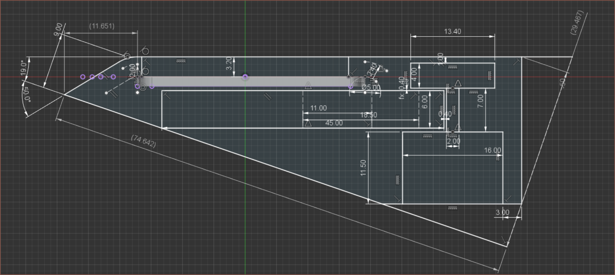
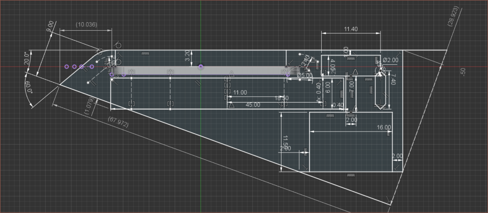
I've finally found my calipers, and the bolt holding the stator and rotor together has a thickness of 1.33mm, so I'd imagine this means that it's an M1.4 bolt. There's no standoffs for that, so I'd likely have to use a long bolt and a steel tube.
 Seems that M1.4x16mm is the longest I can get on ebay, which should be good enough for... this run:
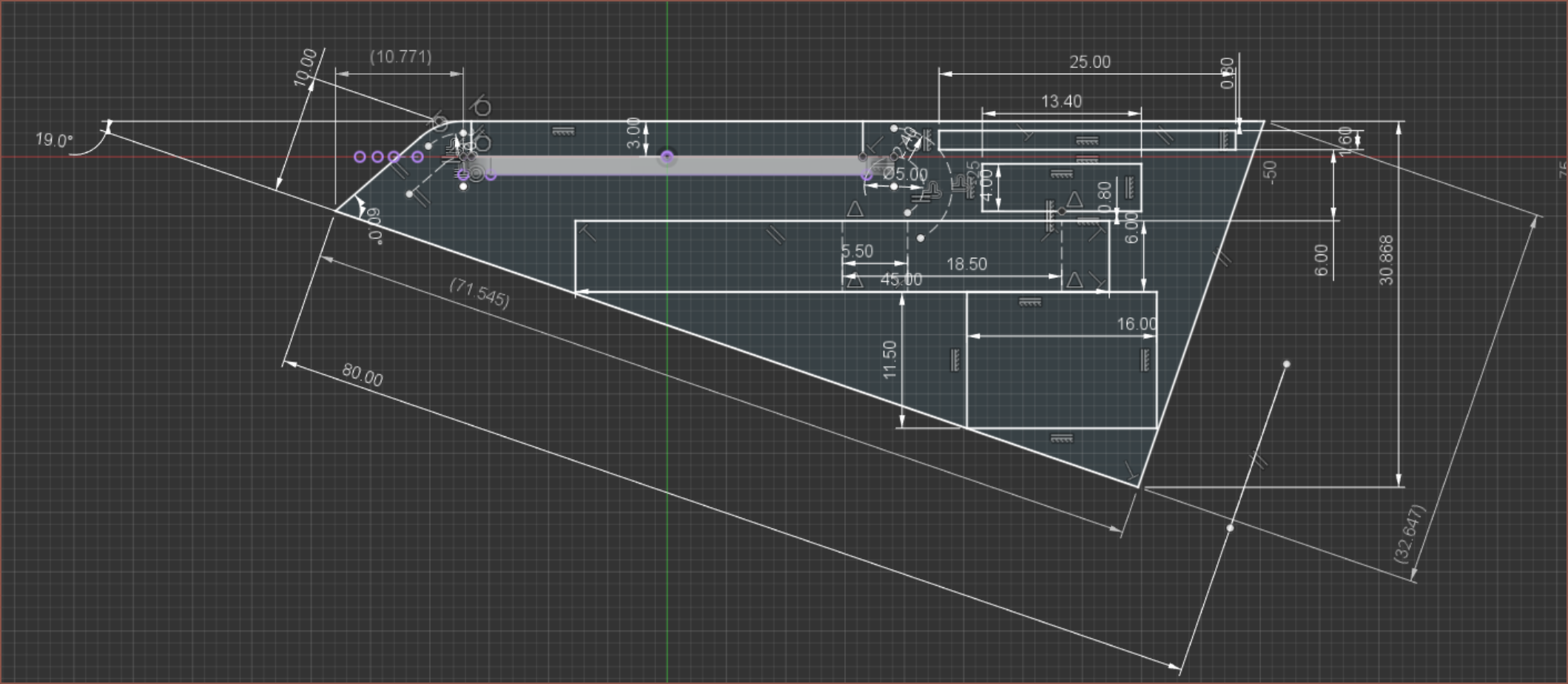 It's suprisingly an improvement on all metrics, with the catch that the front slope is 10mm high instead of 6.5 or so. Not sure how Me In The Future is going to be doing the sliding for TimerSpy.
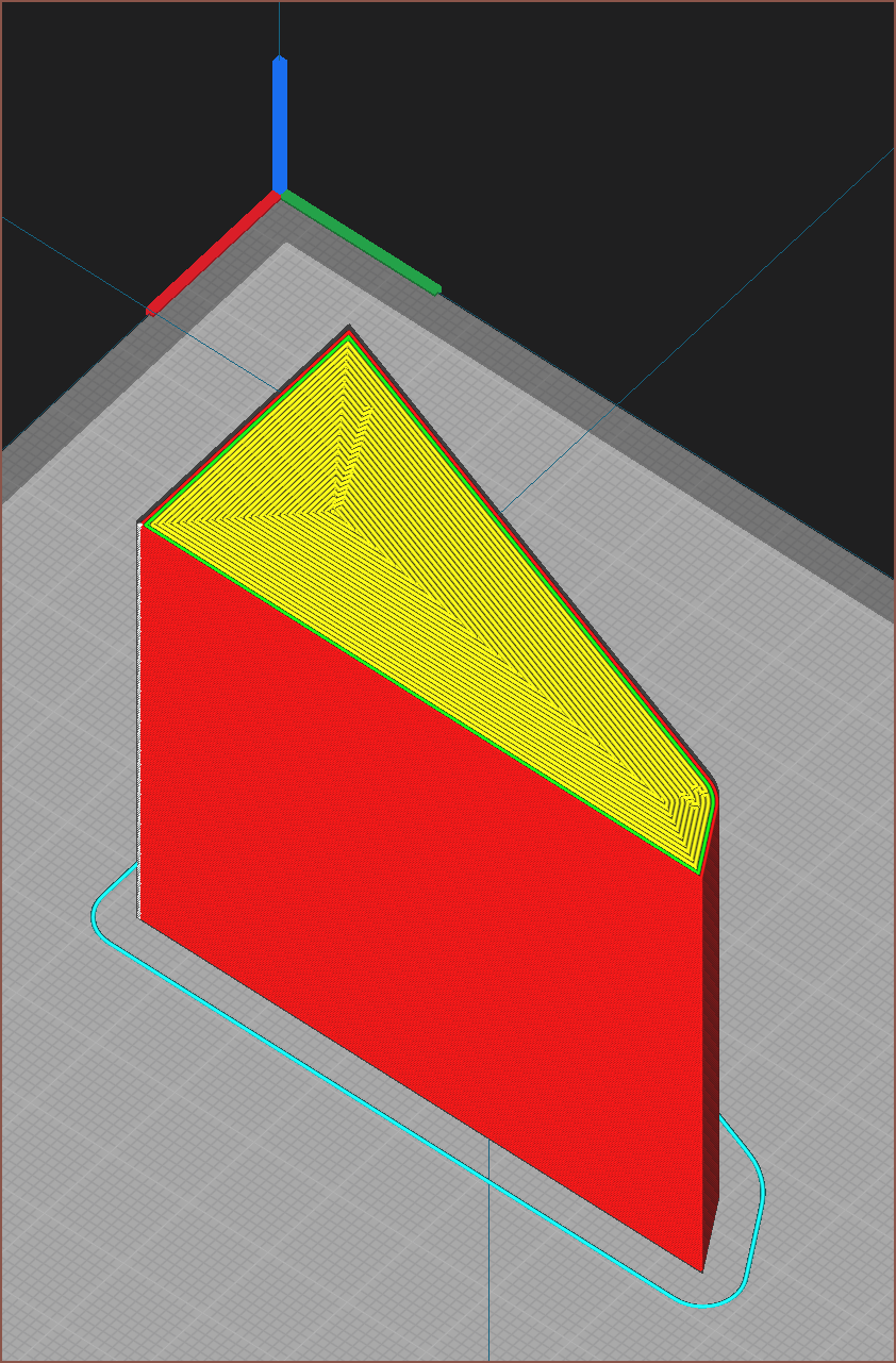 I've printed out the shape envelope (I should've done this for the previous design too but I didn't) and it's kind of tight in pockets, so the solution could still fail. The main issue is the initial slope edges for this 60mm (approx 3 Tetrinsics) print, and that the back pushes on my hand the most. This makes me believe that the concept with the motor sticking out would have fared even worse.
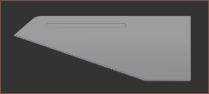 I've tried this too and it's still kind of problematic. Certainly looks cooler on my hand though. That's also a problem, because I've now rejected the solution that has a motor that sticks out. If I can't successfully mine this solution, I'd once again be solutionless.
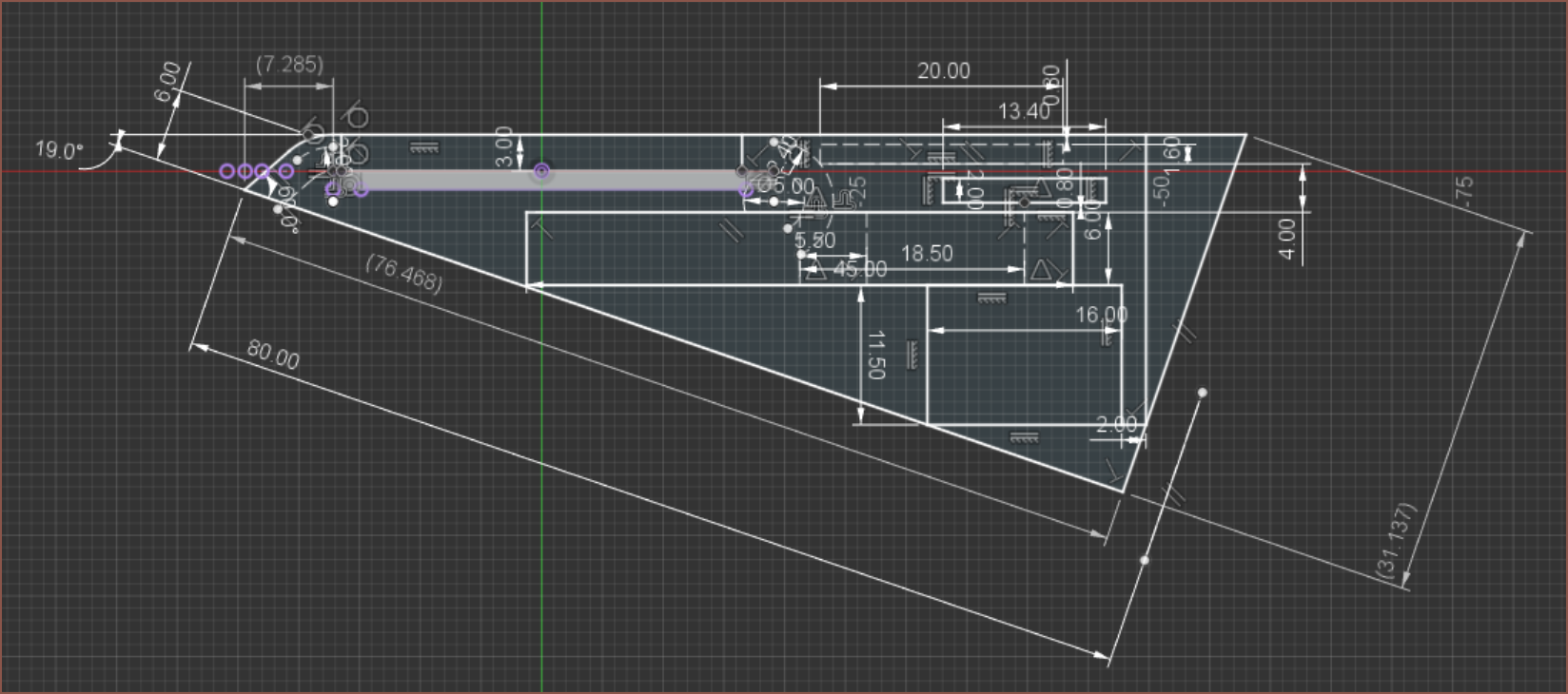 Increasing the length to decrease the 60degree slope height to 6mm is likely to do more harm than good... And then there's also the question of the ribbon cable for the screen.
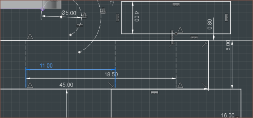 I also got this bolt location dimension wrong.
[19:30] I'll try this, and continue mining for a solution if the print turns out to be successful:
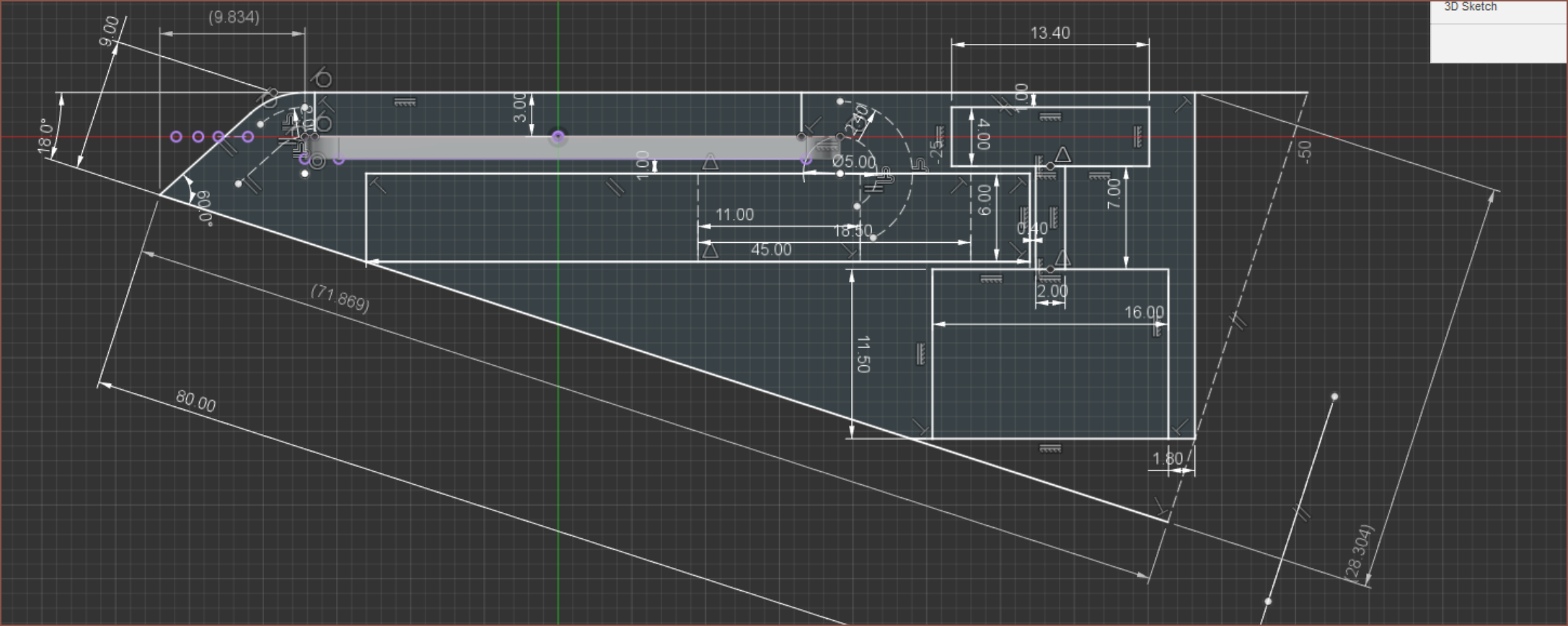 I've also filleted-chamfered the edges:
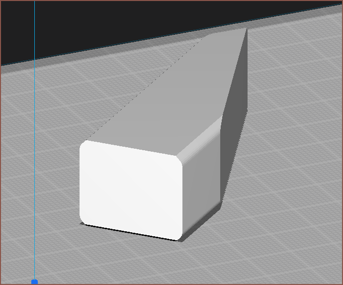
[19:40]
An ergonomic solution...
may exist.
Me:
 Okay... now I need a solution that physically works. There's no encoder in the sketch.
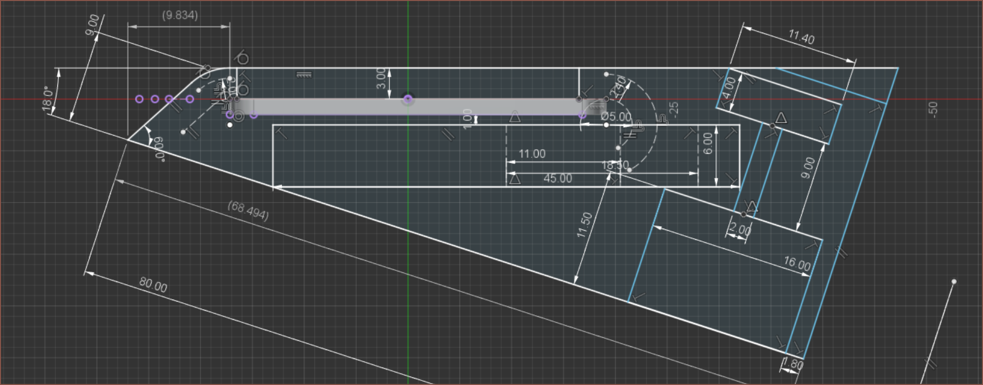 Doesn't seem like that would work. I don't get that much more space for the encoder and the fact that there's a free gap in the latest print (see below) seems to help with ergonomics when the wrist is bent.
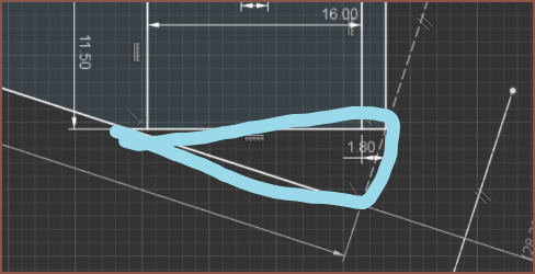 It certainly helps with the ergonomic aesthetic at least.
Let's consult the datasheet for advice.
 Nothing in the realms of off-axis technology?
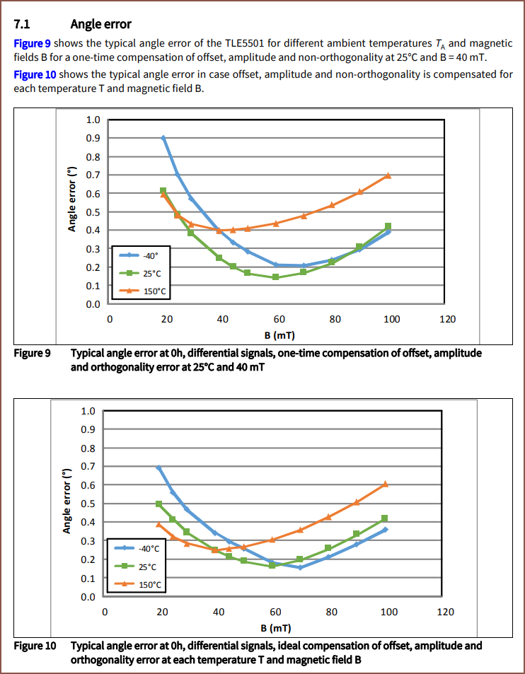 Seems like 60mT is ideal.
 So 600 gauss.
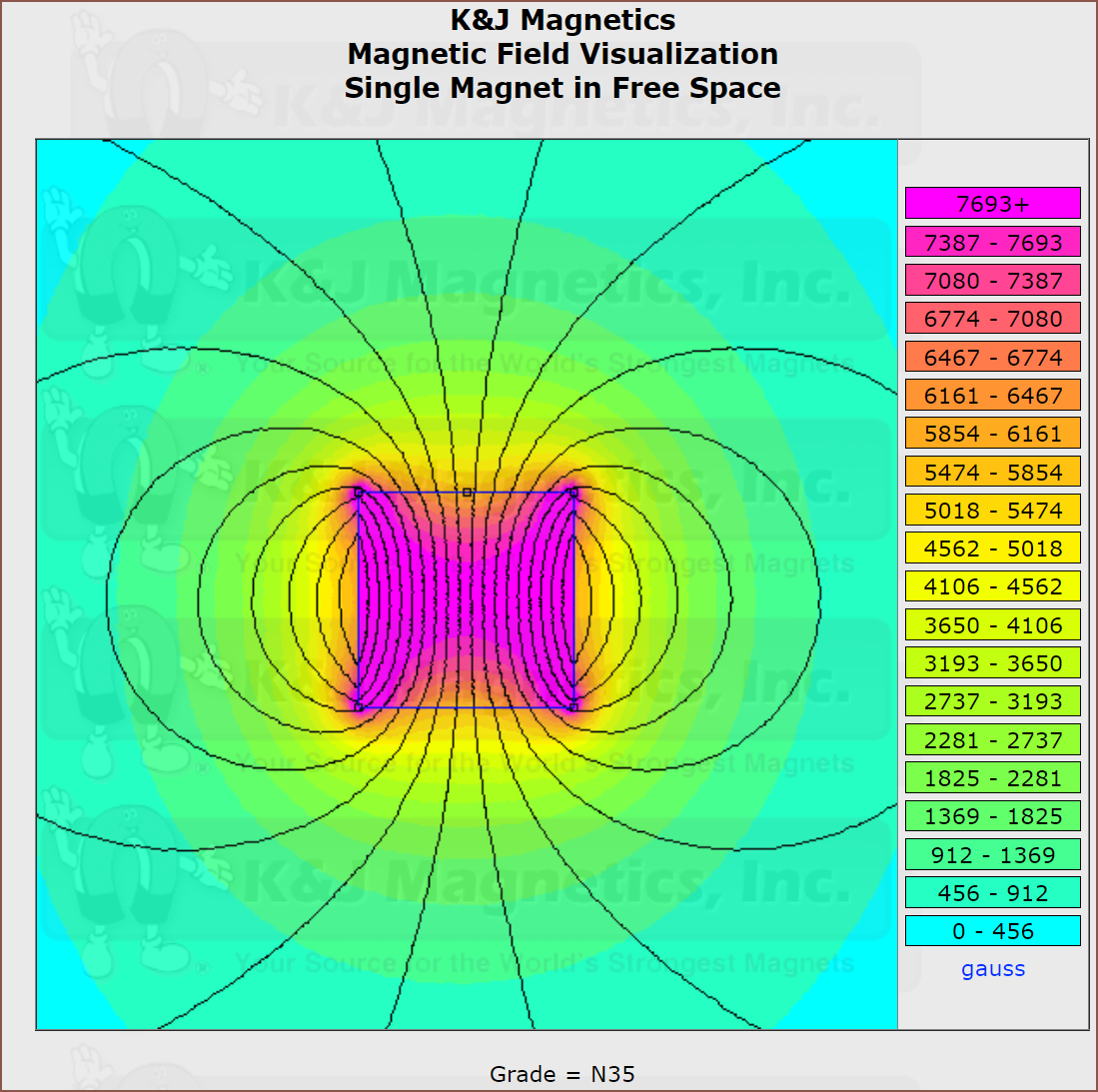
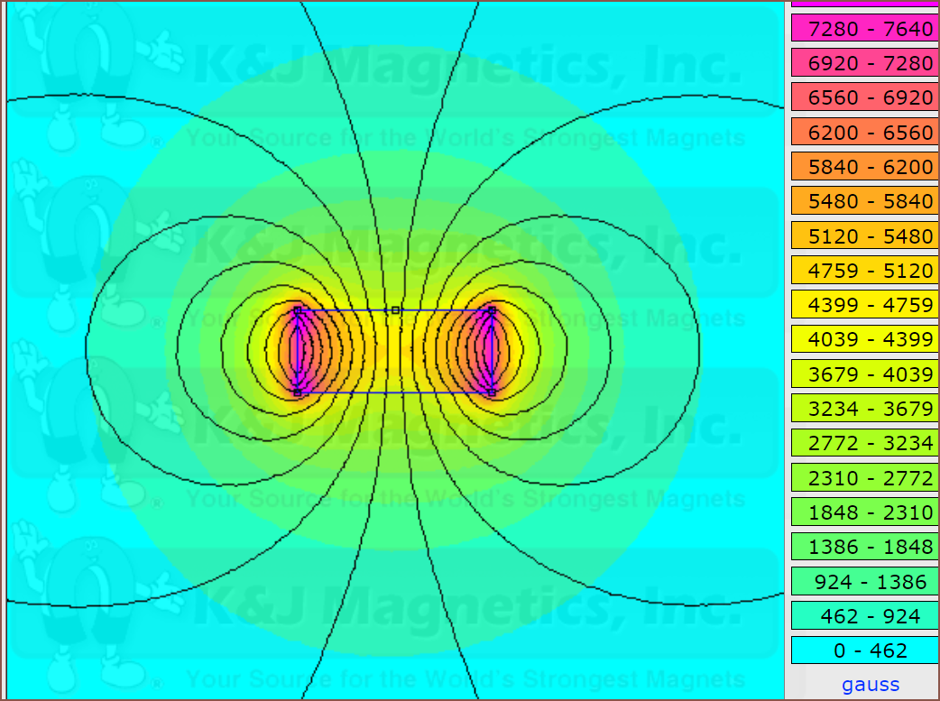
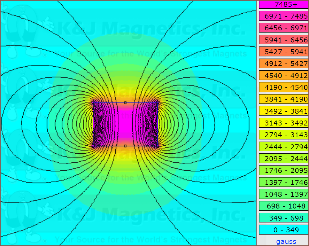
This is a square 6x6x2.5mm diametric square magnet (because a circle isn't an option) and it seems very overpowered for the job. It looks to be >6mm distance from the magnet before reaching a workable location. It seems that something even smaller than the 3mm OD x 2mm thickness radial magnets I got for Tetwin would be closer to the ideal:
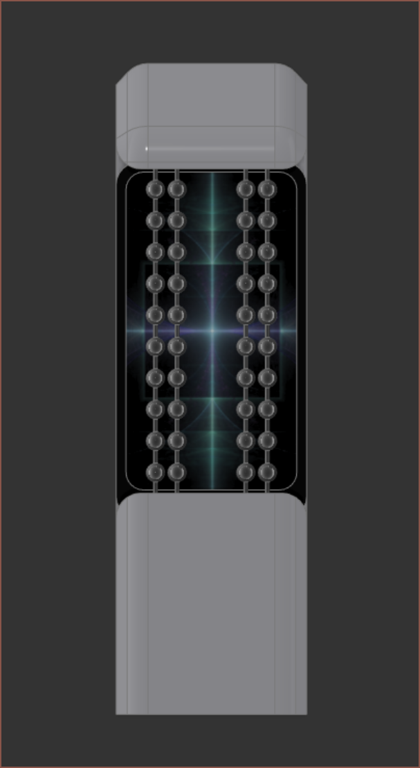
[21:30] Ok, so now that I know that I can use a much smaller magnet, I've got an idea to actually have a cogwheel 90 degrees to the motor-driven cogwheel. The ball-chain would act as the teeth.
 Additionally, I think a shallower initial slope angle of 50 degrees would help instead of 60 degrees.
 The LCD extension cable will have to do quite a bit of origami gymnastics. Actually, I should check to make sure I can even get a cable of the same pitch.
 2.54? That's awfully generous. Too generous...
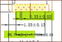
I think it's 0.7mm pitch.
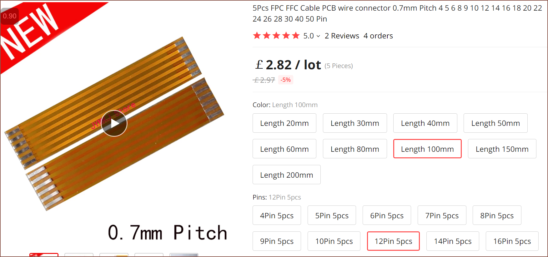 Something like this should be fine.
 [21:55] Ok print finished and it doesn't seem like 50 degrees did all that much other than poke into Finger5. It seems that 75mm total length is a bit iffy. Yeah, I really should've printed out the second Gen3X1 concept before going into TestCut because it probably would've failed.
 If I get a file, I probably could get another few mm's in...
[20 minutes later...]
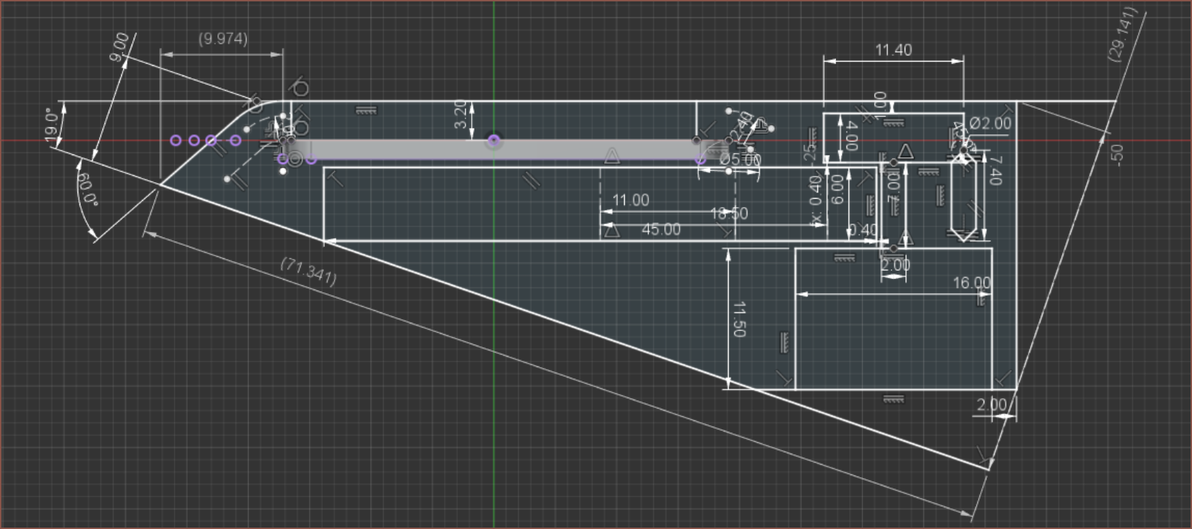
 That should be manufacturable.
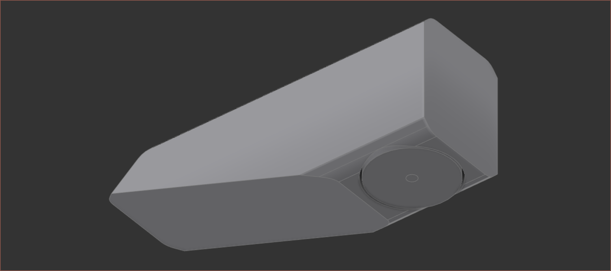
[22:50] I printed it and
An ergonomic solution...
may exist.
Not a fan of the fillets though...
Filleted chamfers or nothing is going to have to do.
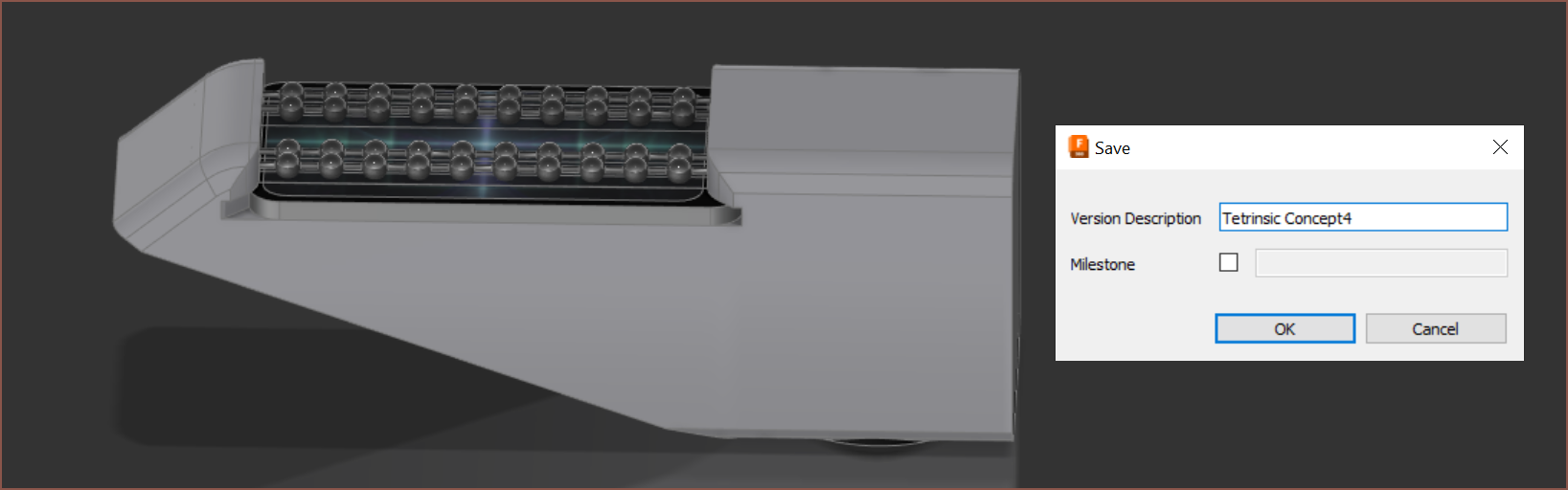 It's a new PCB method so it's essentially a whole new concept now.
It's taken 6.5 hours to get to this point. If I average 1h/day after that Feb 1st deadline, it means that the progress I'd usually manage in a day will then take a week. Ouch.
Solution mining... ends, in 19 days.[13 Jan, 05:38] Render:
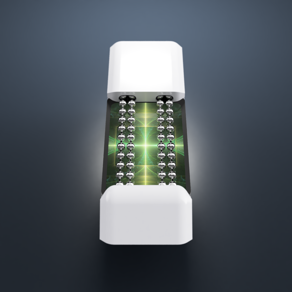 It actually looks like something's missing when there's no motor sticking out.
Discussions
Become a Hackaday.io Member
Create an account to leave a comment. Already have an account? Log In.