 kelvinA
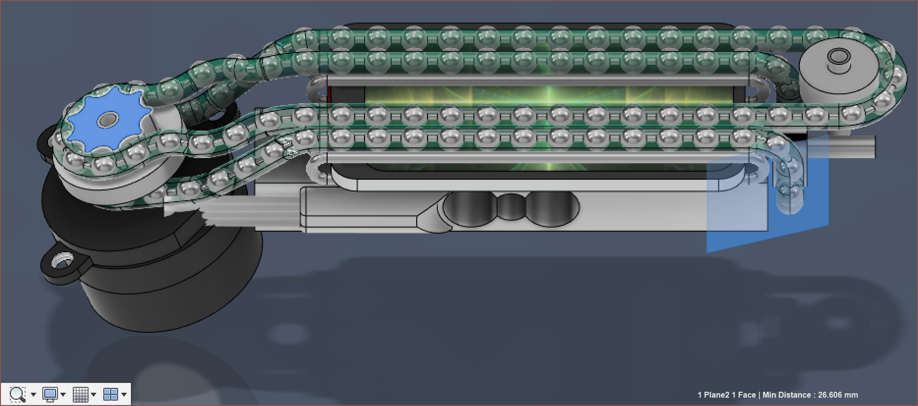
It's been another 6 or so hours of modelling... once again.
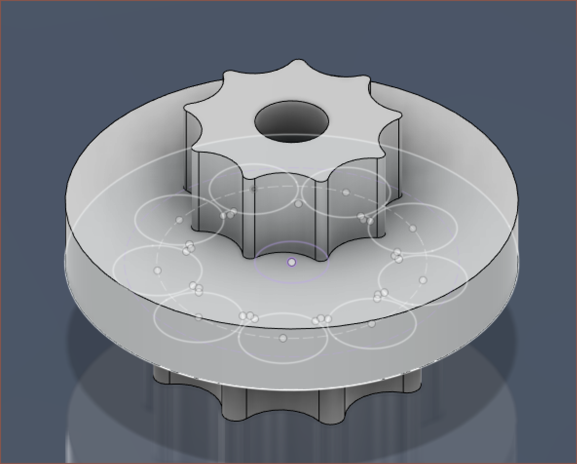
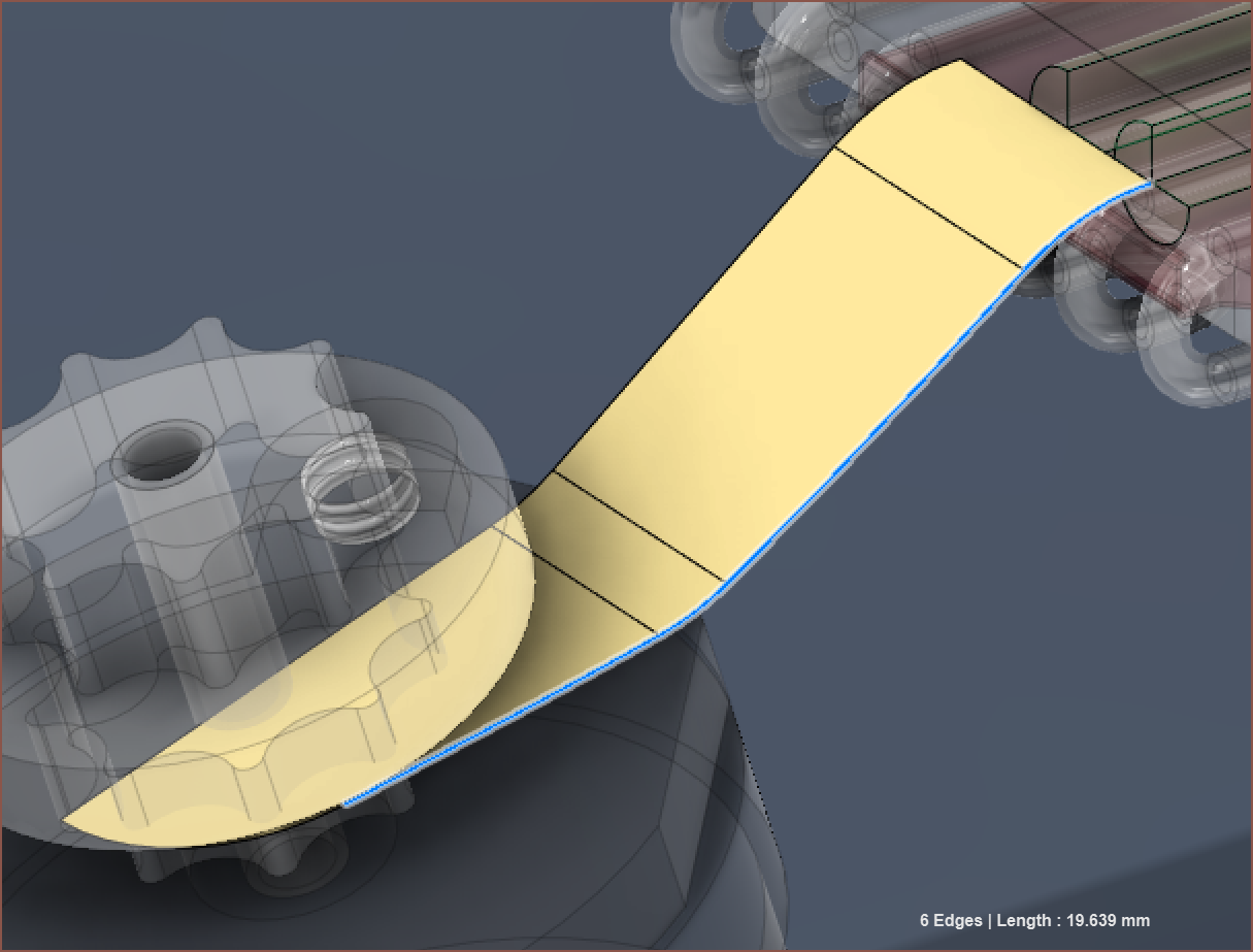
So I started off with modifying the 3D pathway so that Fusion would generate a centre-pathway:
followed by a long process of a misaligned chain:
Eventually, I knew I wasn't going to get anywhere tweaking things until the distance from the pulley to the slide-tubes were the same for both the top and bottom paths.
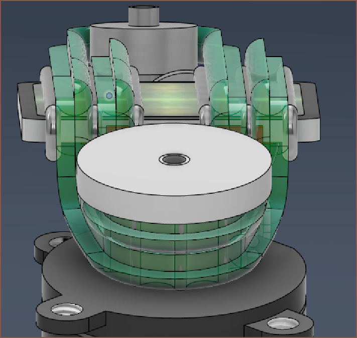
I decided to use a unique property of ball chains, which is that they can "compress" with absolutely no opposing force until the balls themselves are touching each other. Thus, I tweaked the pulley to have 2 different diameters, trying to keep over 2.5mm ber-ball distance for the smaller one and under 3.1mm for the larger one:
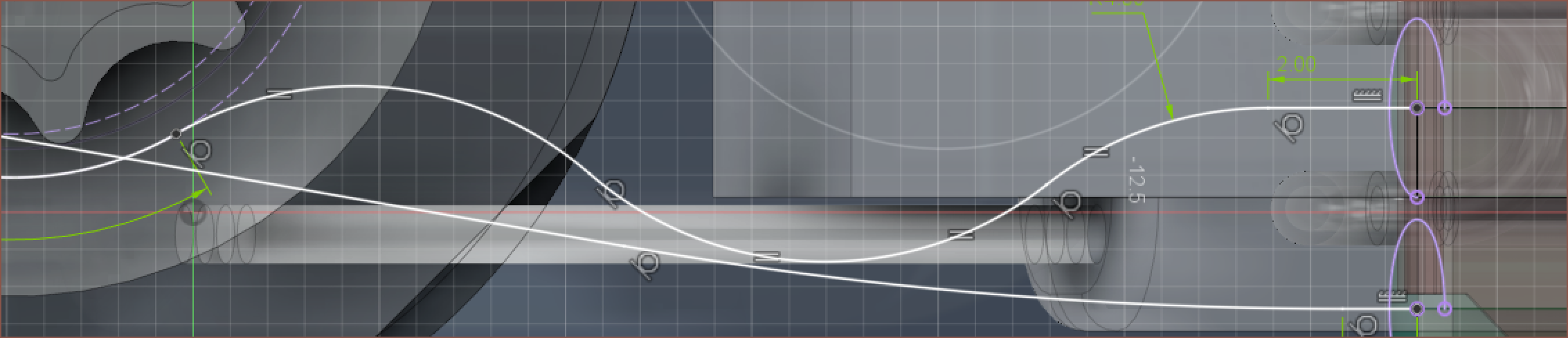
Then I had to tweak the paths so that I could get distances from the point where the ball left the pulley (as this is where the chain would be tensioned, with a 3.2mm ball-to-ball distance distance). Essentially, I shortened the bottom path to as low as it can go, and then increase the length of the top path to match:
Then I manually got the position for this bearing so that the ball positions were equal on both sides:
When it came to doing the same on the other bearing, there was an issue that I was going well below the minimum height plane:
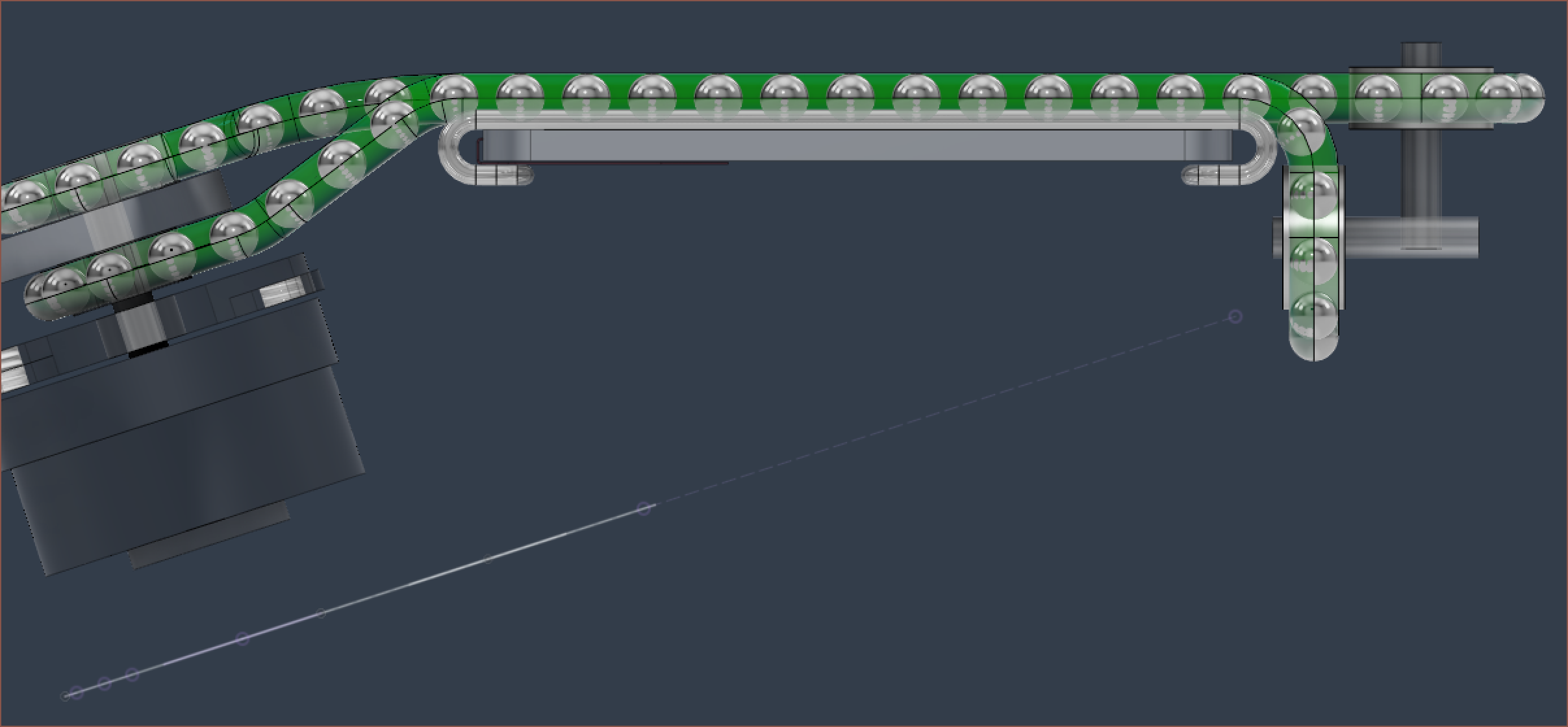
Annnnnd... well I looked at this for maybe 6 minutes and deduced that there wasn't going to be any solutions to minimise this, so I decided to just bring down the load cell and increase the amount of space I can use for a 3D print to hold the screen. At least now I don't have to worry about how I'm going to hold the screen + sliding tubes now. At least the "flat height" is less than 27mm still, though this is without the top screw that holds the shaft onto the motor.
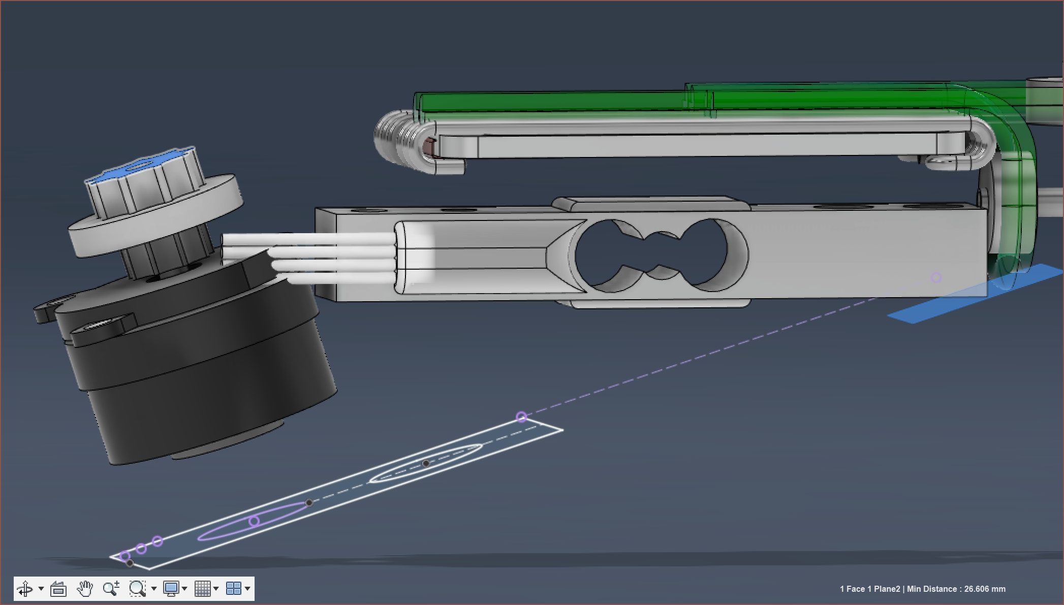
You can also see why I was weary of Tetrinsic Gen 1 having a width of 19.6mm. It's all too likely that stuff needs to be moved around and expanded, potentially increasing that size to 20mm and beond. 19.4mm is already just barely enough, going from the 0.8mm spacing in #Tetent [gd0090].
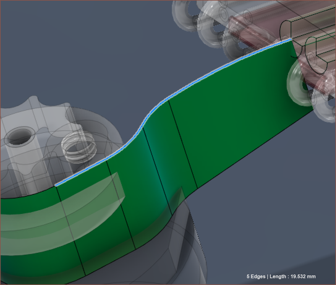
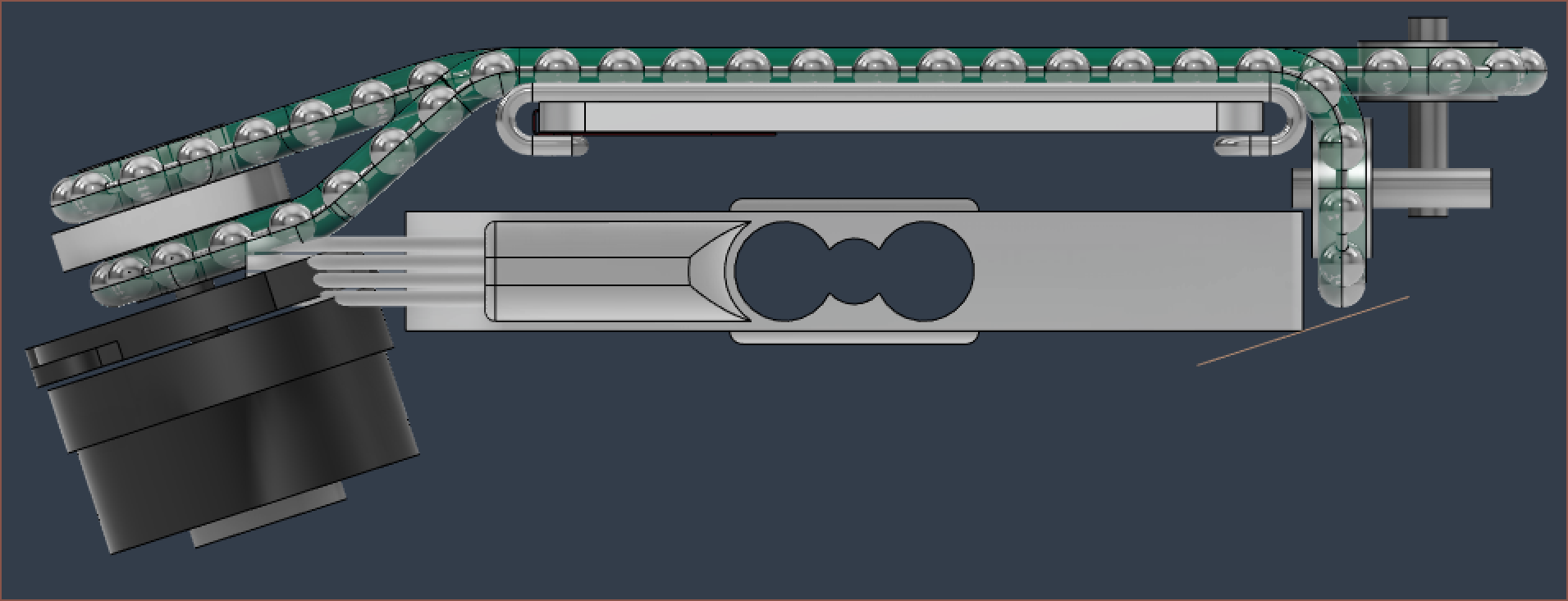
Anyway, this changes all the paths again and my original pathway now intersected with itself. Obviously, when you've got some differential pairs, the strat is to do things the PCBway.com:
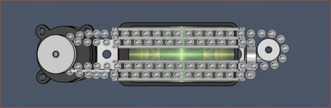
This path starts 1 ball later than the bottom one, so the length is 3.2mm shorter to compensate. I also formulated the actual equation needed for the 2 bearings so that I didn't have to manually calculate it again.
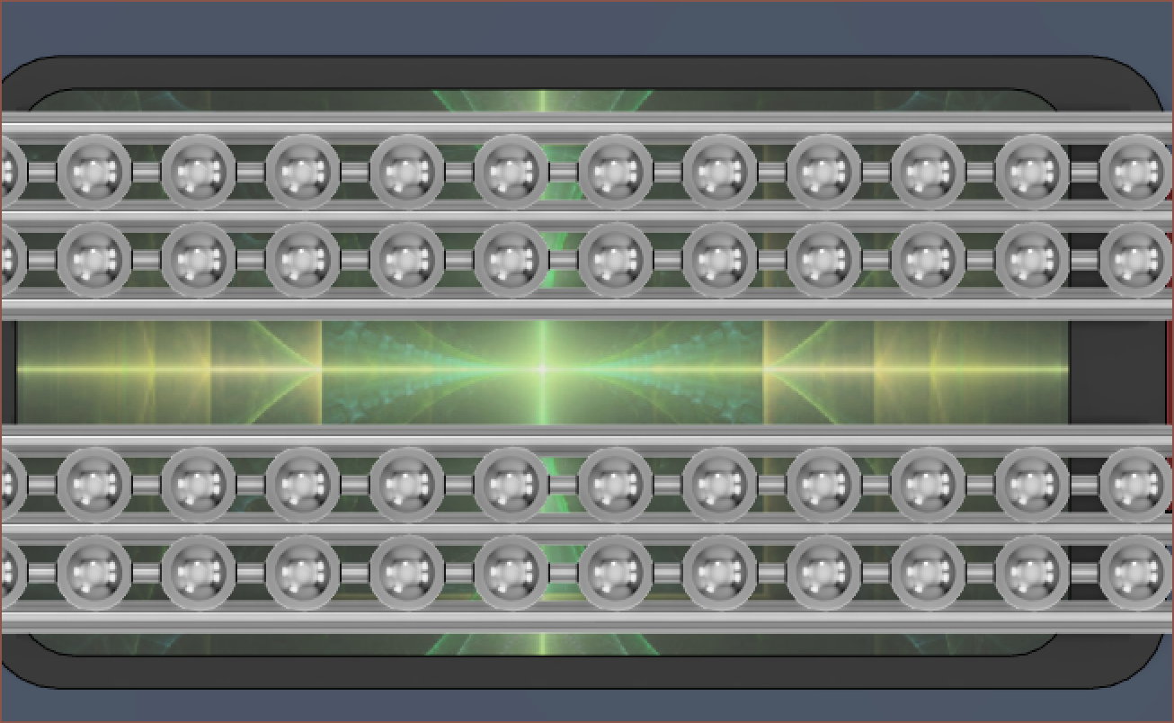
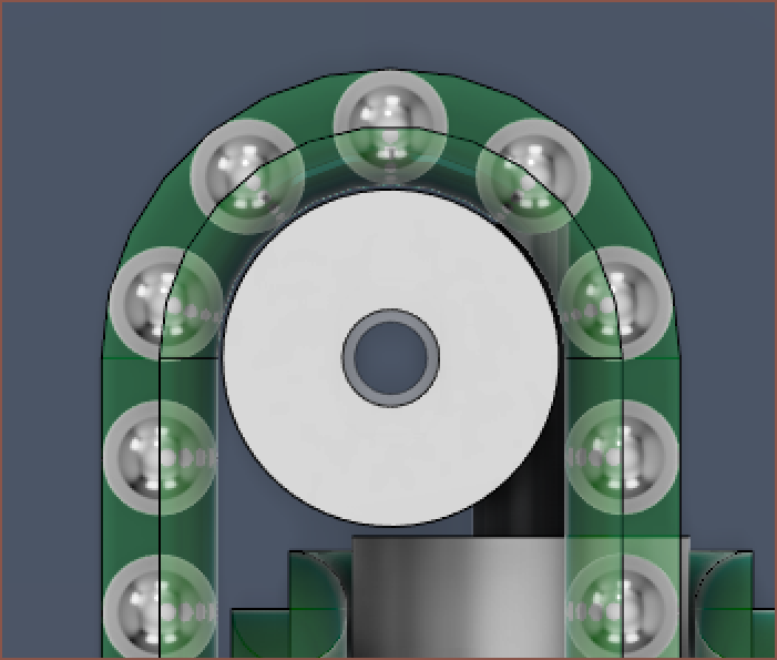
Now I've got some lovely, aligned balls. It also looks good from the side.
Now with all that under-screen space, I'm wondering if a solution exists to have the PCB exist there and send wires off to the angle sensor (just like the load cell wires).
- That sensor is the only one that is in a non-QFN package, so it seems like a simple and straightforward thing to do.
- Allows uninterrupted access to the 2 mounting screws.
- I don't have to solder an extension flat calble to the screen, which I guess negates the top point.
It's quite the tight fit though. There's only 3.35mm of space.
Discussions
Become a Hackaday.io Member
Create an account to leave a comment. Already have an account? Log In.