 kelvinA
I thought I'd just get it over and done with regarding these new chips.
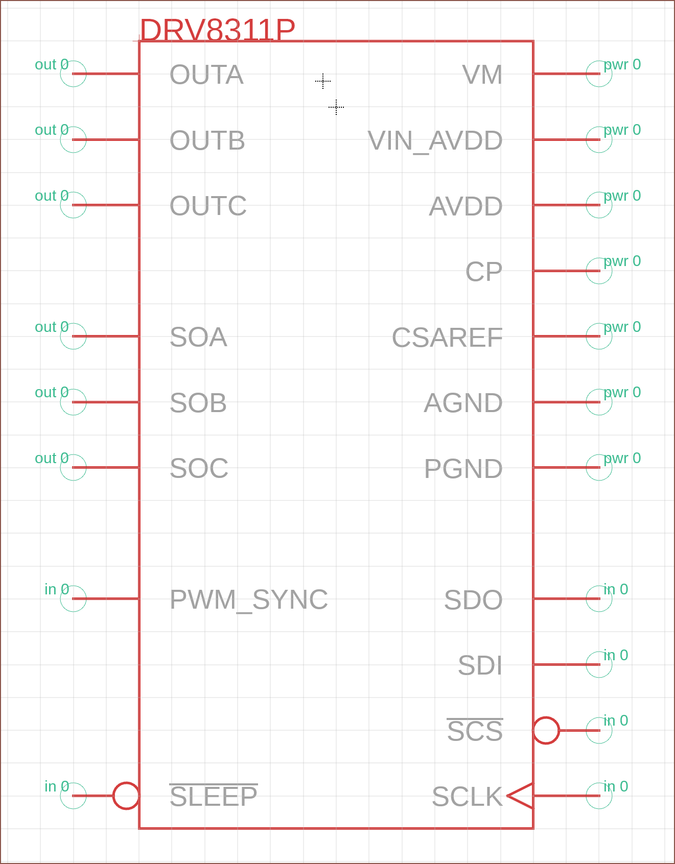
The symbol was straightforward:
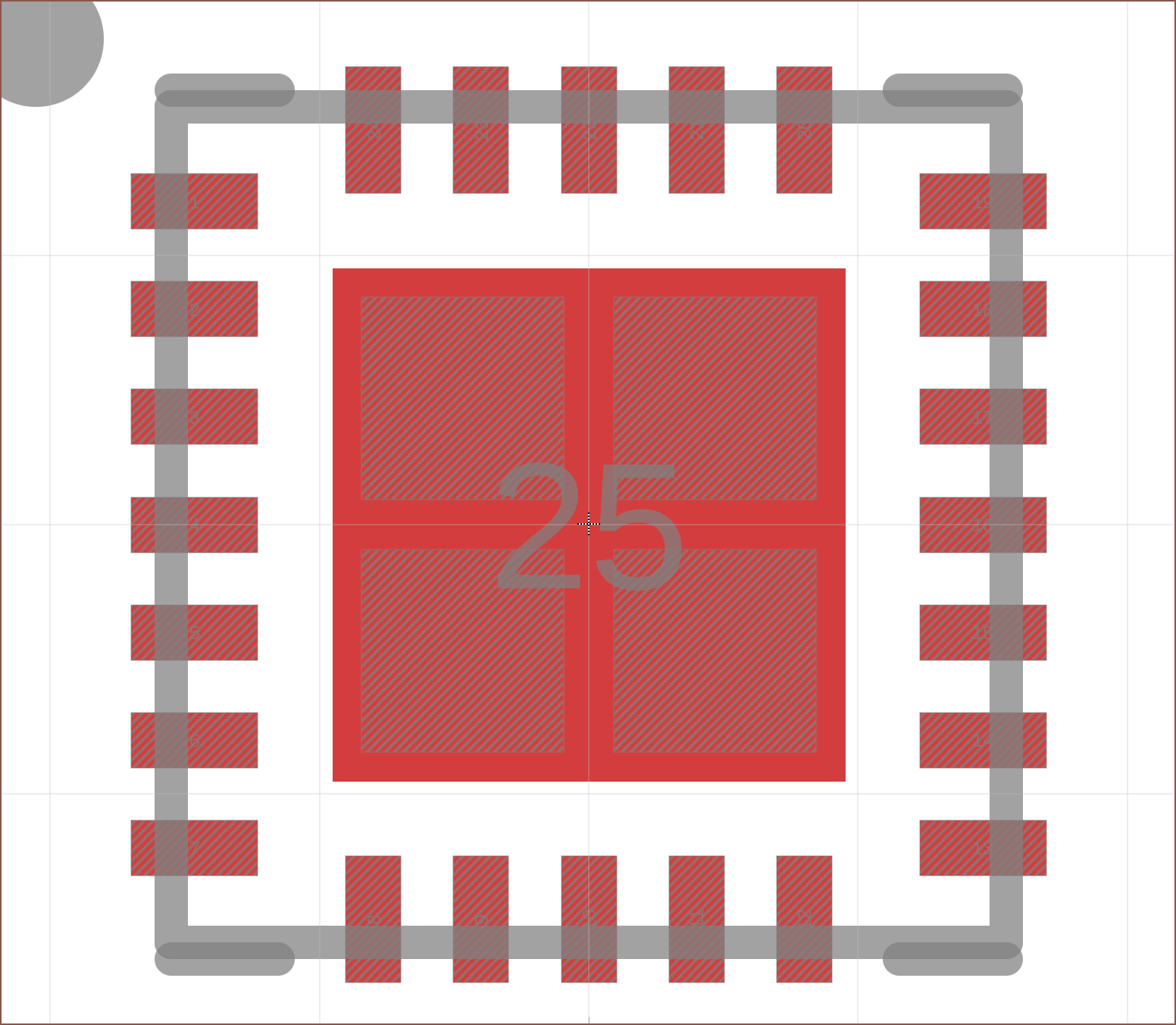
The pad though, totally isnt:
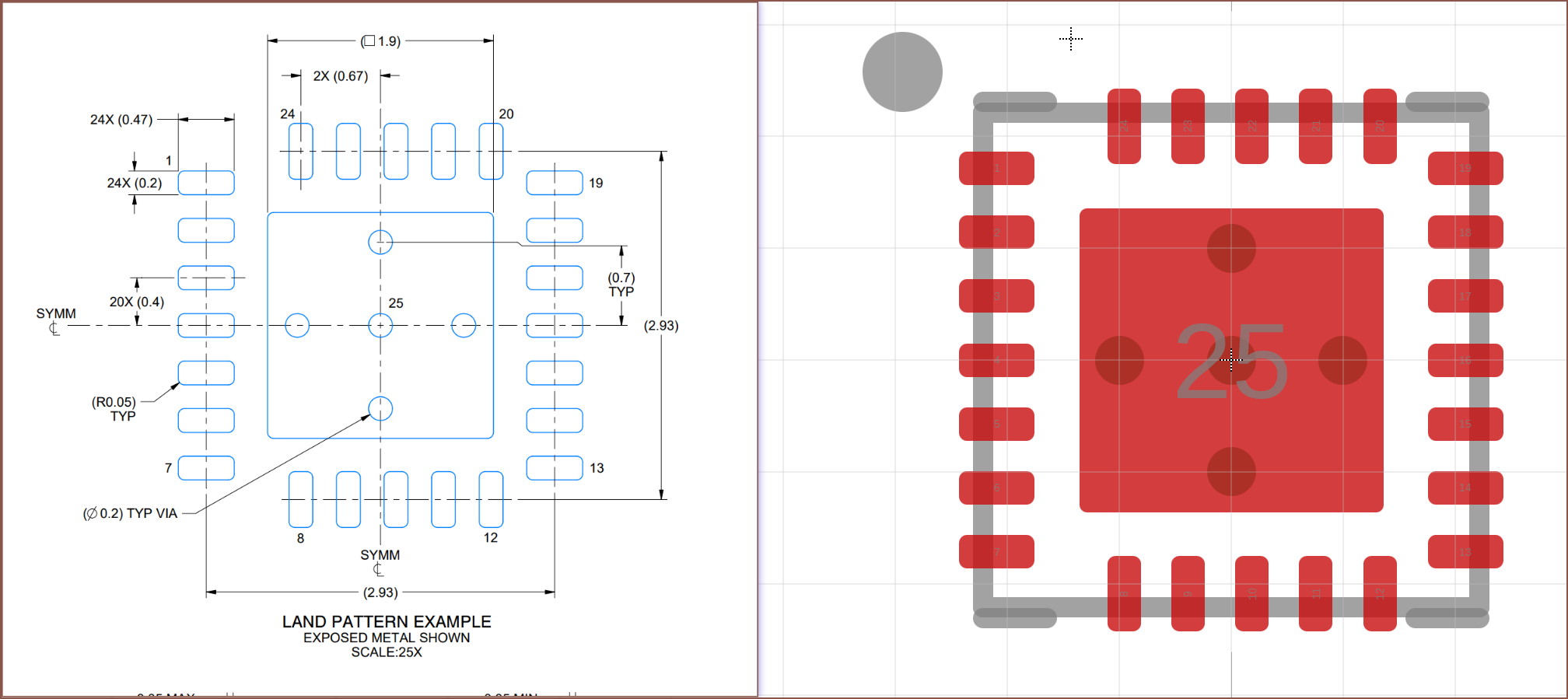
The top/bottom pads aren't centered and so I had to change the grid to [generated position] - 0.67mm. In this case, it was at 0.8mm so the grid was set to 0.13mm so that I could drag the pins. Then, I calculated the roundness percentage of the pins, which is 50% for everything other than the pad which is approx 5%. Lastly, I changed the grid to 0.35mm so that I could spawn circles which I put on the via layer. I looked at JLCPCB ahead of time, and it seems that there are multiple min-via sizes and I'd assume that the other ones cost more.

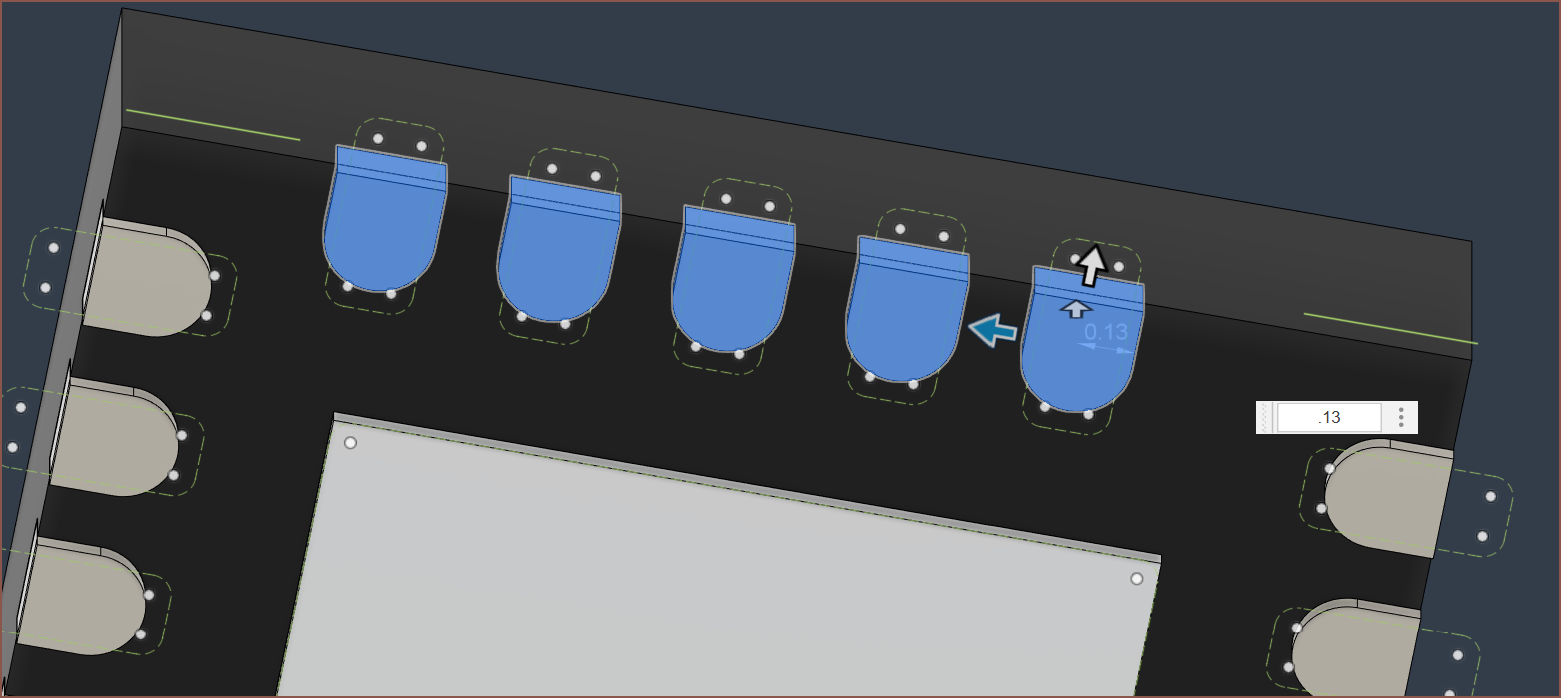 Unlike how Fusion 360 is usually nicely parametric, I have to manually move these pins over even though the footprint would be updated automatically. It's also a shame that there's no way to specify rectangular pins along with your rectangular pads.
So I do all that, and then I scroll to the next page:
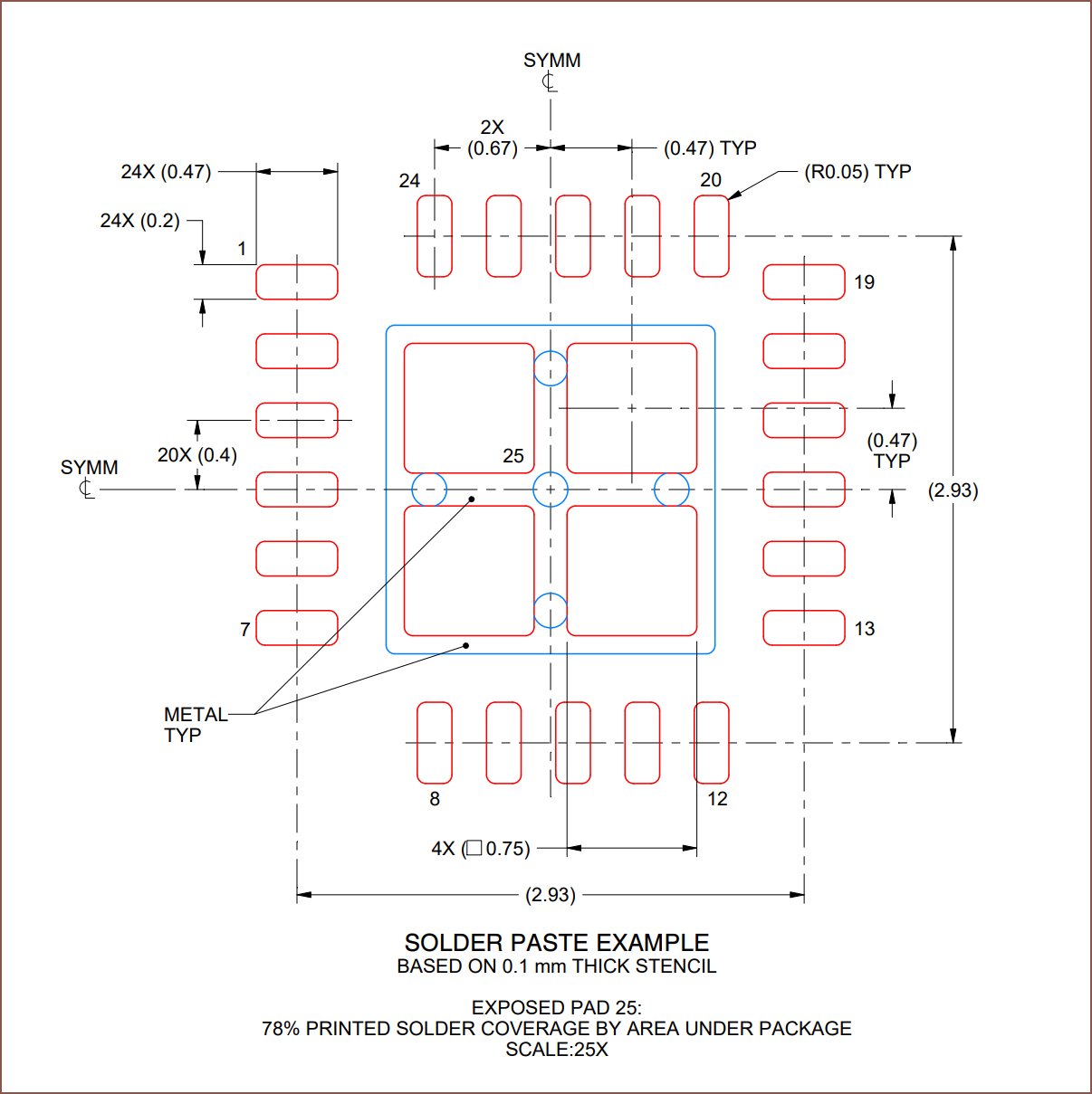
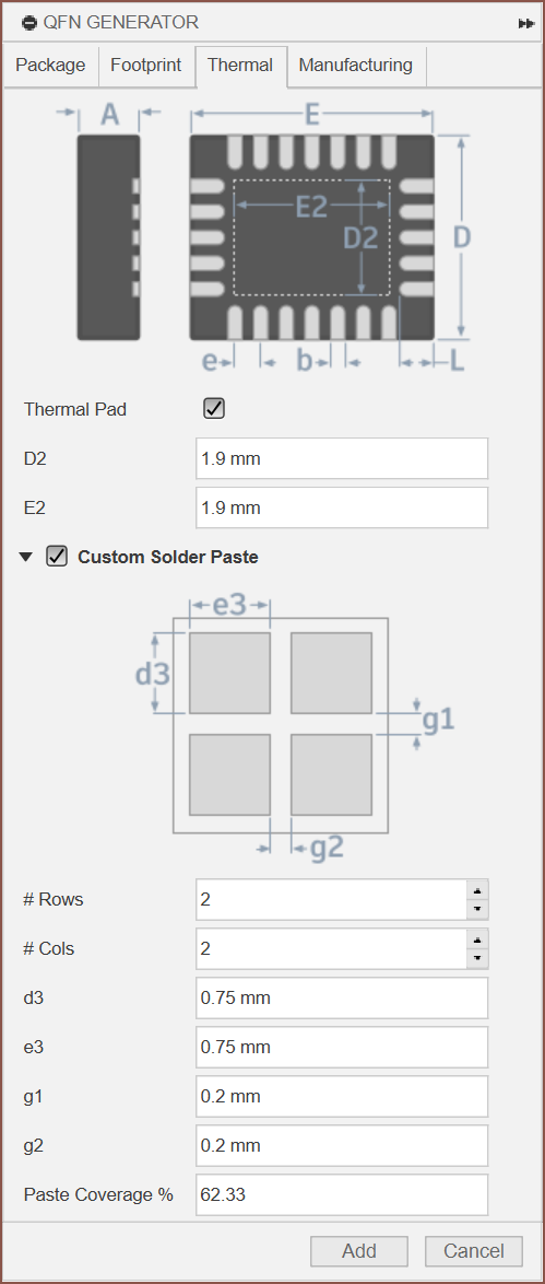
There was this window that I walk passed and skipped. Now this wouldn't actually be an issue if Fusion 360 actually reverse-synced the package to the footprint, but it doesn't. So I'm now doing this all over again to get the correct tCream so that I can copy-paste it.
Not sure why Fusion 360 Electronics likes to throw me under the bus when it comes to footprint creation. It just seems unpolished with a hint of legacy design architecture.
Discussions
Become a Hackaday.io Member
Create an account to leave a comment. Already have an account? Log In.