 kelvinA
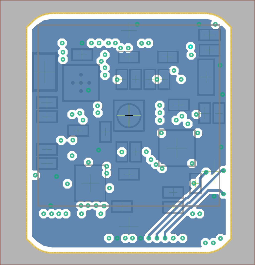
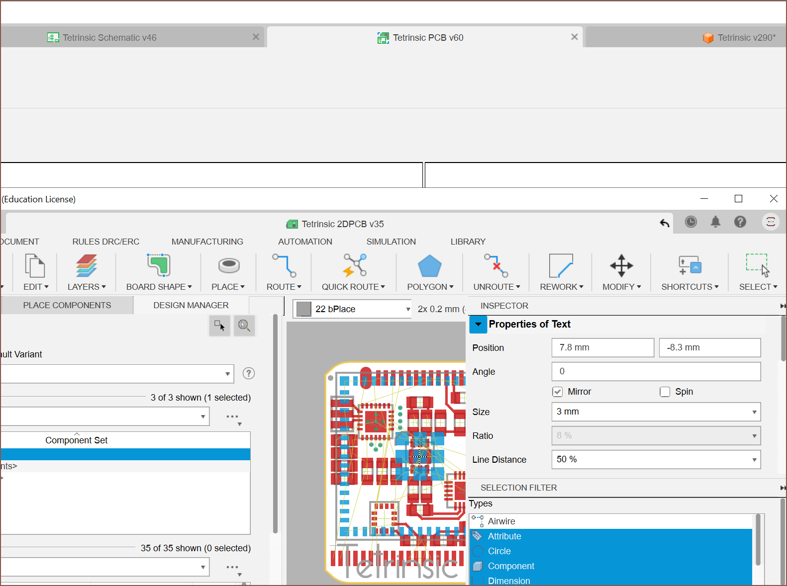
Starting the grind at 14:30, I found out that you can drag the Fusion 360 tabs out to put them in new windows (see below). This helps loads because I could now view the schematic and PCB side by side.
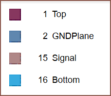
Then I found out how to change the colours of the layers and opted for ones that were more comfortable to my eyes. I also decided that I was going to have 1 interior signal layer and one GND copper pour. I put the pour under the Top layer to potentially help with heat dissipation from the BLDC controller.
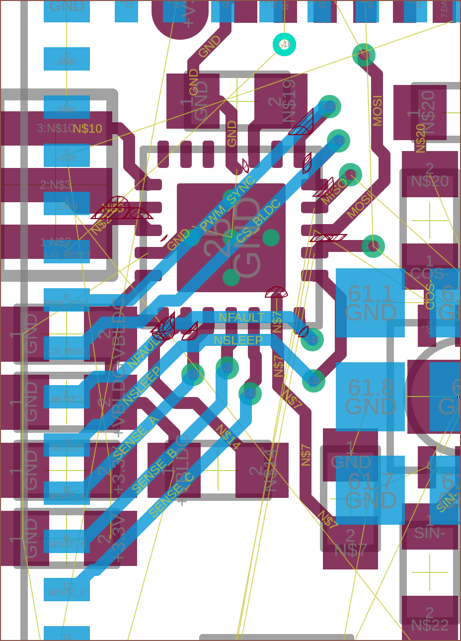
By 16:30, I had gotten some connections onto the BLDC:
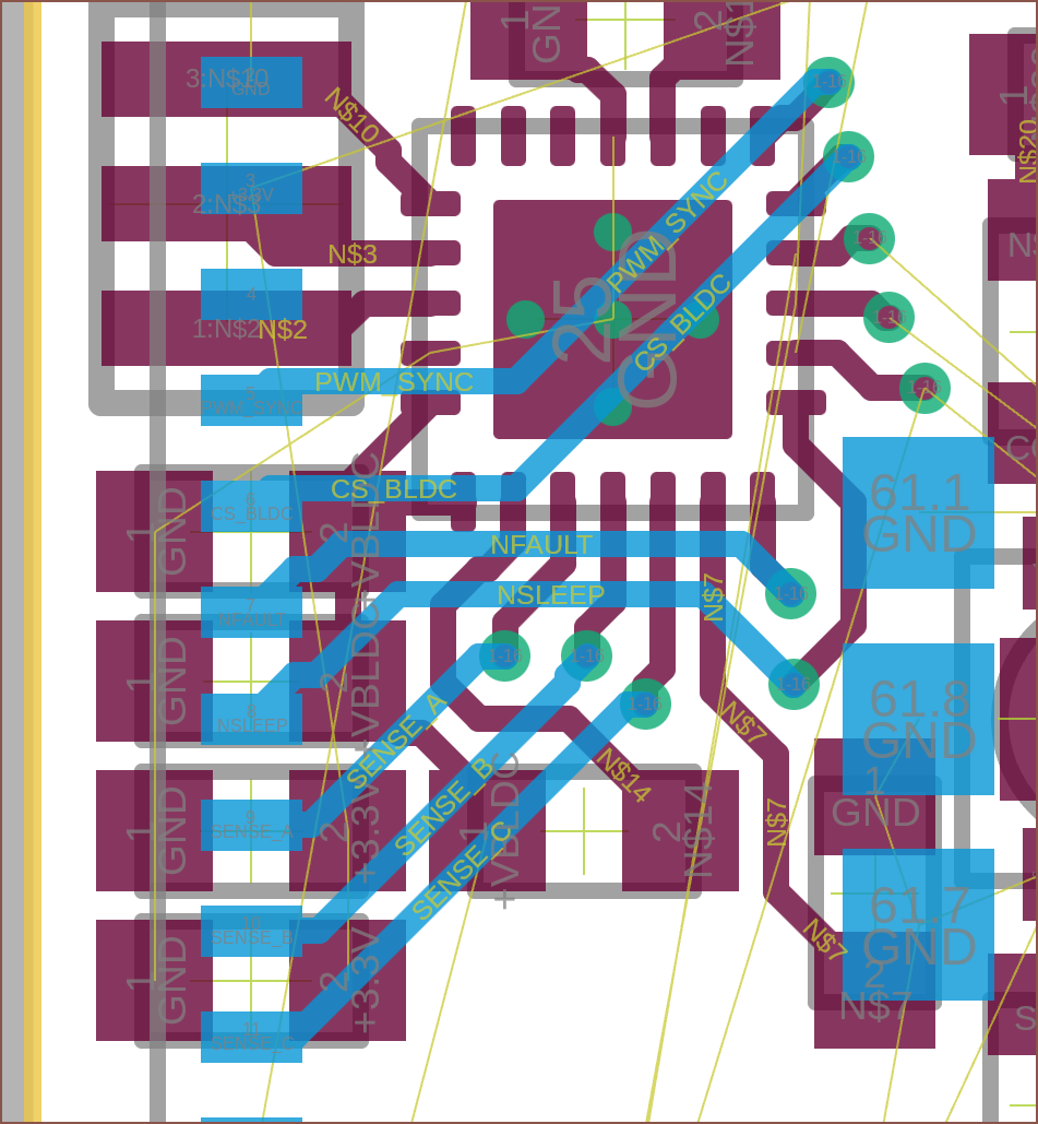
It was already starting to look like mounting the MINI-1U module on the back was a great idea. It would take much more space to route out if all components were on the same side. Unfortunately, I had to fint in a via so I had to do a select-and-move-surgery:
Oh, and I changed the EXPn index to start from 0.
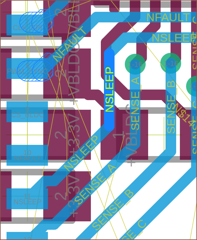
What you see above was very nice to see. It's what happens when I join up an incomplete trace. It's now one long trace. In EasyEDA, they'd be seperate entities and so I'd have a lot of complete but segmented traces.
2 crashes later, it's now 20:30 and I've tweaked the masterpad order and have now fully connected the BLDC controller, the IMU and managed to get all but EXP0 (connected to IO0) on analog capable pins (which gives me the most flexibility for implementing features).
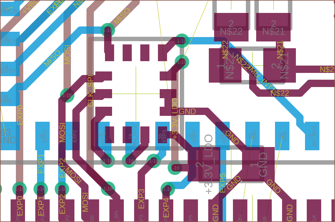
Then I remember about POSITION, which is on the right other side of this masterpad and it needs an analog-capable pin. I just used the last one. After looking at my options, I decided to move the MISO pin over and then have a long trace to POSITION:
After a 30 minute break staring at trees (and imagining they're actually all virtual like I'm wearing a futuristic VR headset), I come back rejuvinated with the goal in mind to make #Leti so that I can work on projects while I stand/walk outside.
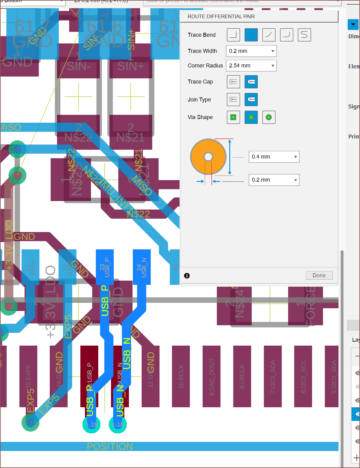
At 21:30, I found out how the differental pair worked. While I didn't do this for the ADC inputs, the routes I neded up with seemed close enough to a differential pair anyway. Oh, and I watched this video that helped speed up my tracing workflow:
I thought it was a bit early, but I wanted to give the copper pour feature a go. I selected "Copper pour from outline", cliced the edge of the board and it actually worked. I had to click on the outline, not the pour, to get the inspector to activate, and then I changed the net to GND.
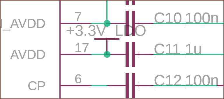 It was 22:30 when I found out that I actually missed the supply connection for the LDO. 8 minutes later, and I'm seeing the real power of this push-pull nature of tracing:
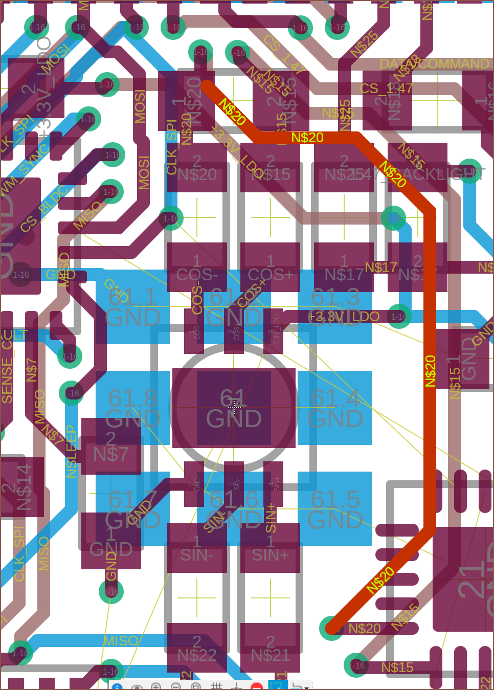 I actually forgot to route this trace after routing a few other ones, and I still miraculously had enough space to place that top via thanks to Fusion 360 pushing things away. EasyEDA would've been a complete ripup of so many traces... might've taken 64 minutes to do that, not sub-4.
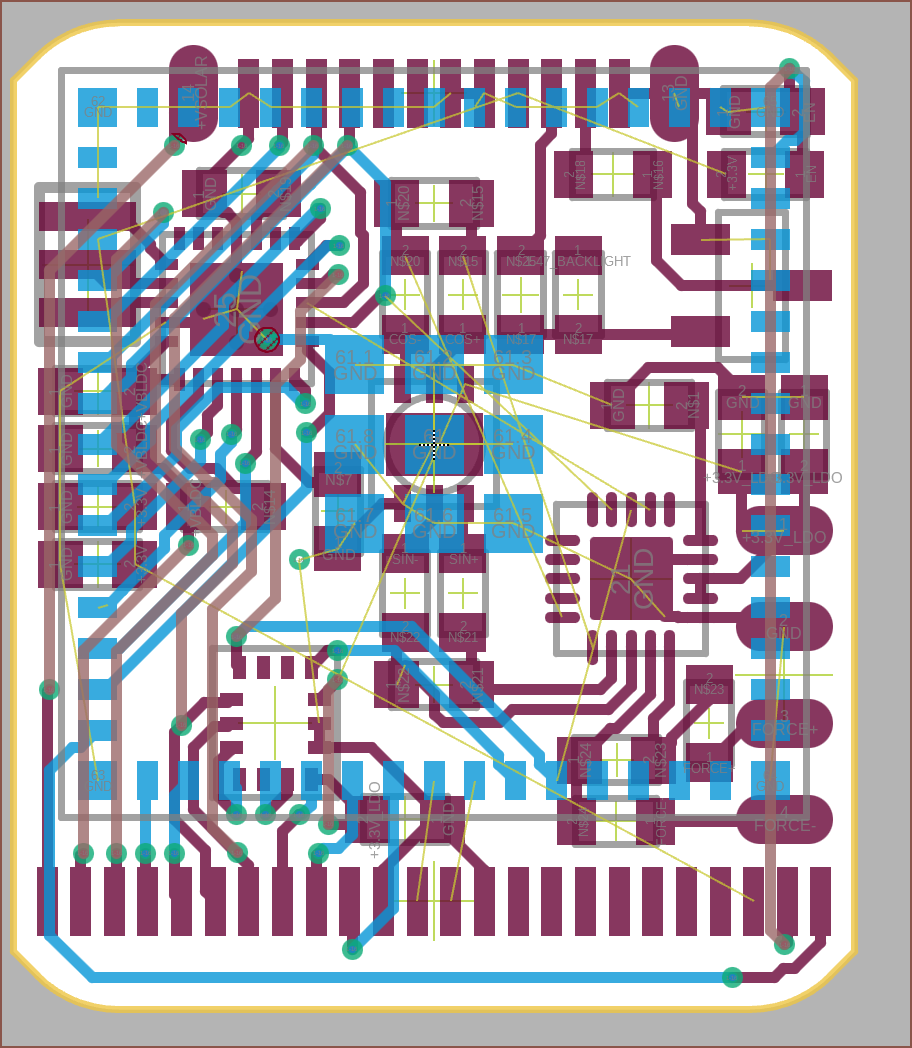
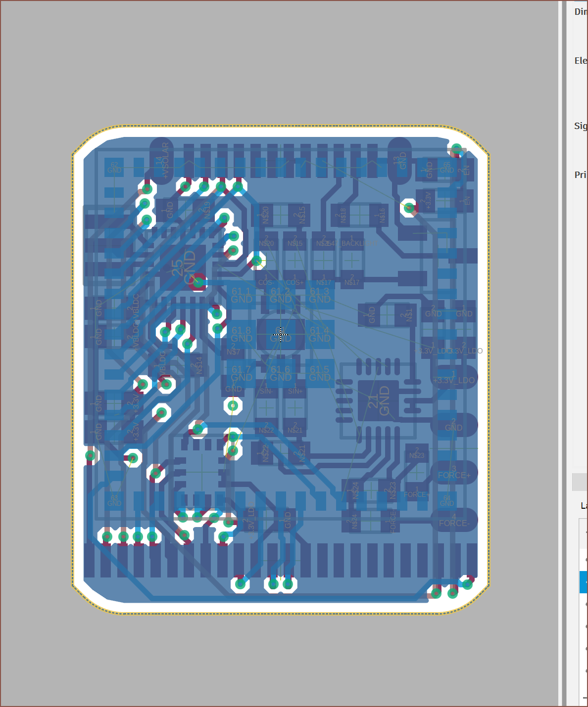
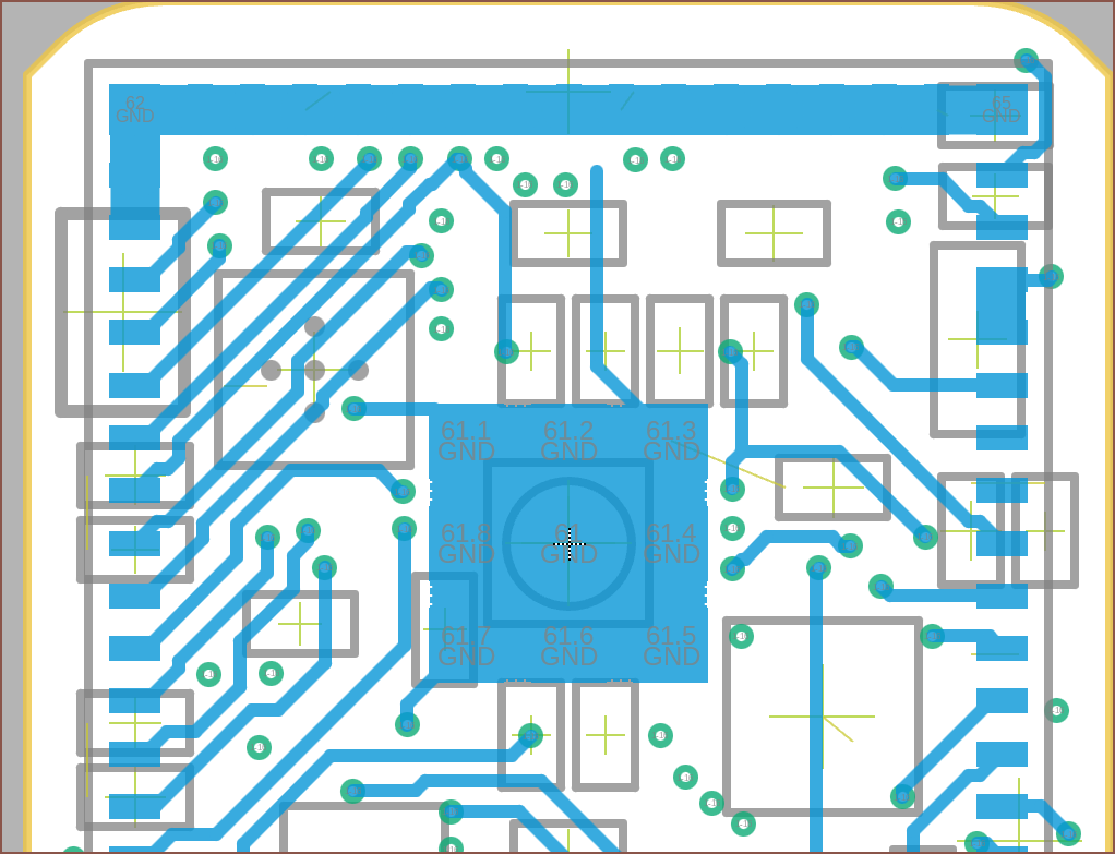 At 00:30, I was connecting the last of the airwires. I initially thought I was going to copper-pour the bottom layer too, but there's so many traces that it wouldn't be very useful. Oh and Fusion requires every pad to be linked up; it's not enough to start a line at Pad 62 (top left corner pad) and finish it at Pad 65 (top right corner pad). I even encountered what seemed like a ghost AirWire, but since there was only 1, I could use the QuickRoute feature to fix it. Oh yeah... that QuickRoute feature I was talking about last log. Yeah, because it tries to link every Airwire from the same signal, it usually fails. "Manual Routing" is still a good bit more automatic than EasyEDA Online (Standard Edition) ever was. Anyway, I thickened some traces like VSOLAR and VBLDC and here is the result of 10.5 hours of work:
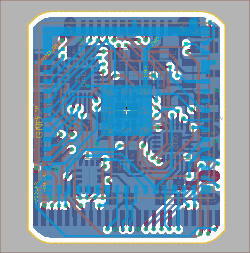
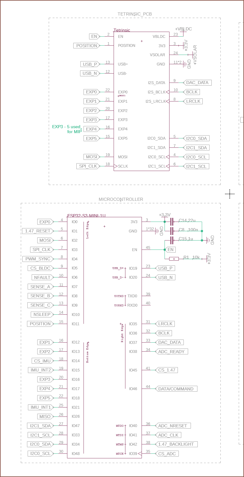
Here's what everything got connected to on the MINI-1U:
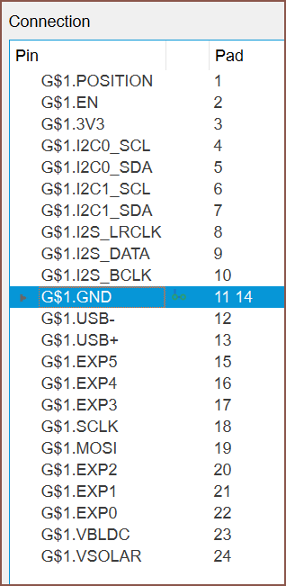
And here's the pinout of the masterpad:
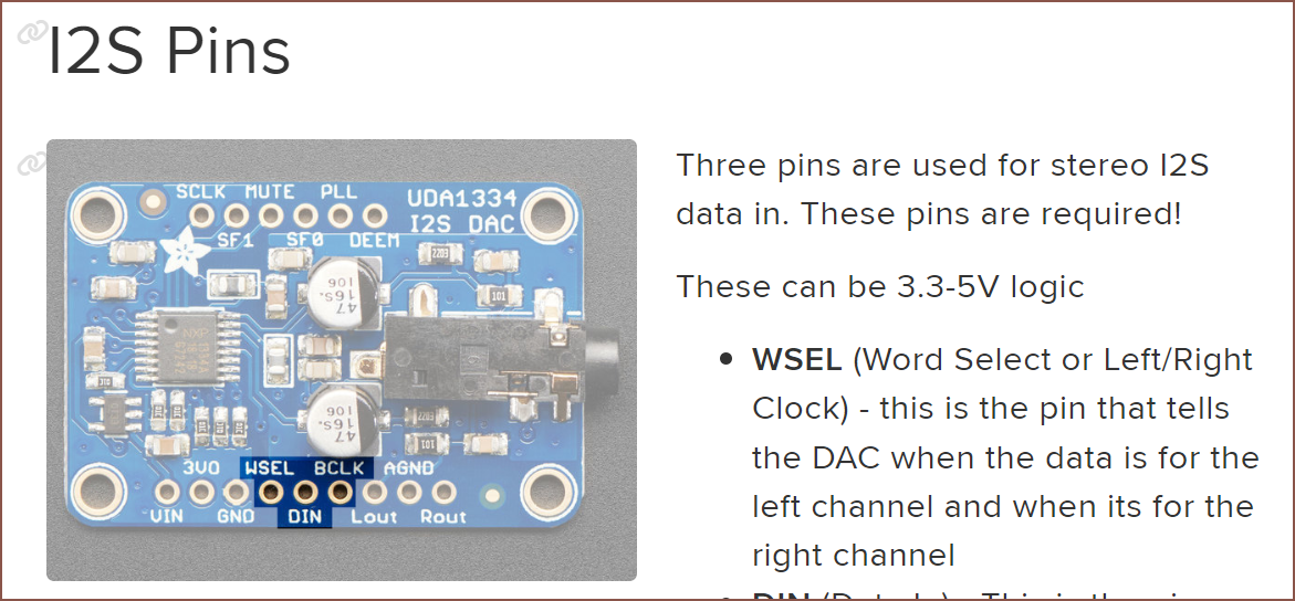
The order of the I2S pins were chosen based on one of Adafruits boards:
Discussions
Become a Hackaday.io Member
Create an account to leave a comment. Already have an account? Log In.