 kelvinA
Before I stopped researching once and for all, I had a look on Panelook for the largest screen that's less than 18mm wide. I found the TA016XVHM05 which is an SPI AMOLED panel that's 45mm in length (which means that I could have a 3d printed circle extension, as 45 + 18 = 63). I can't seem to find this anywhere, nor what it even looks like. There's also a MIPI panel (TA016XVHN05) that has 31 pins, and it seems that it's used in the Xiaomi Mi Band 6. SUNSKY has the lowest price where I've found the panel, which also comes with front glass for that extra premium look.
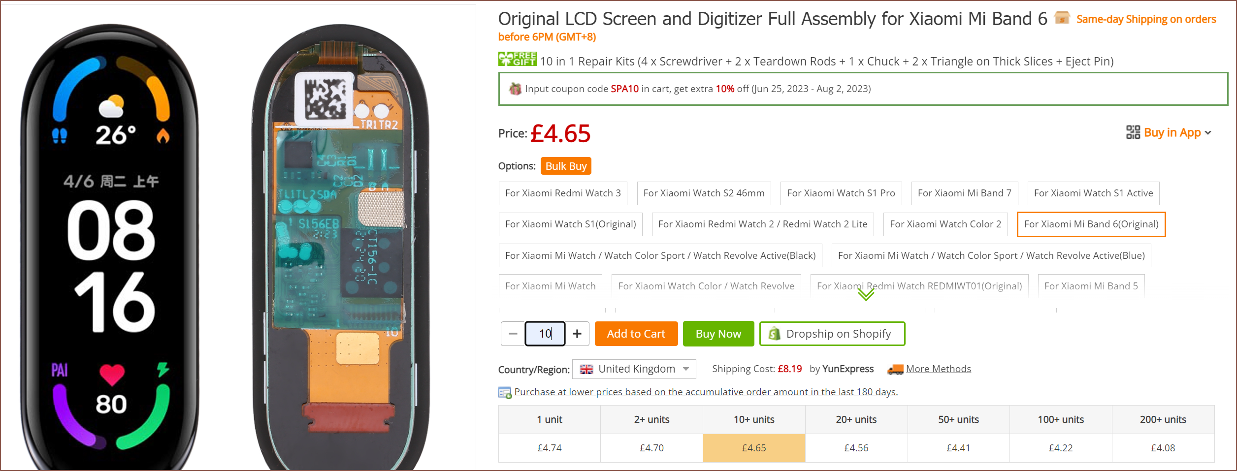
With shipping, it's £5.10/display for 10pcs, or 55% more expensive than dual 1.14" screens.
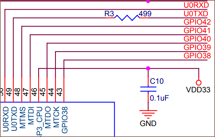
Speaking of those LCDs, I'm going to have to tap into the unused UART pins:
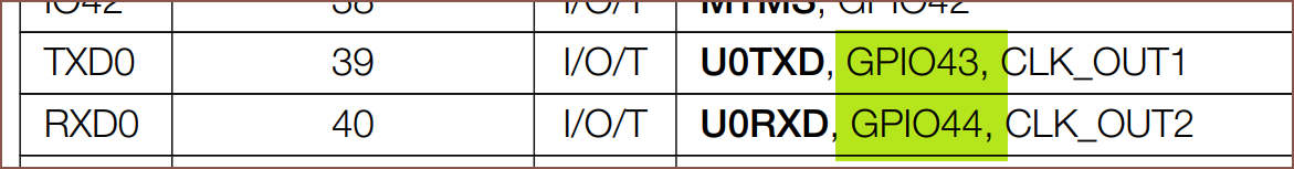
The good news is that these pins are right next to where the current display CS and backlight pins are. I was wondering if I should just drive both backlights with just one pin, but considering that each screen is likely to have brightness variances and that if I'm using one of the UART pins, I might as well use the other one too, I then decided to see if I could somehow fit the circuitry for 2 backlight drivers.
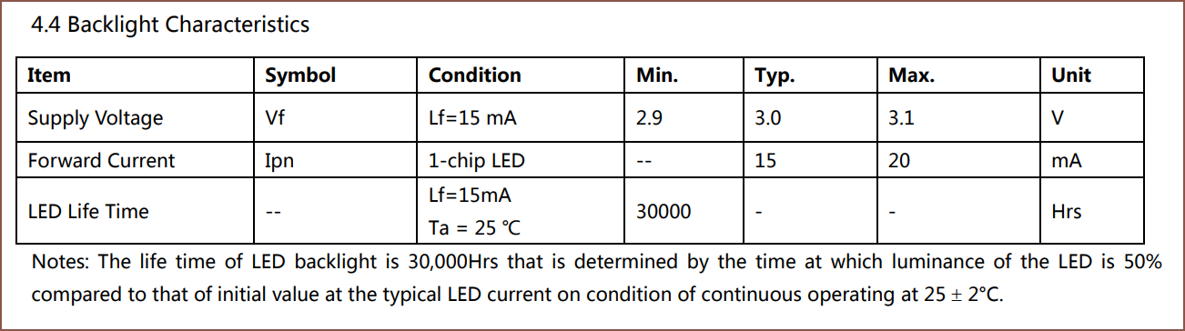
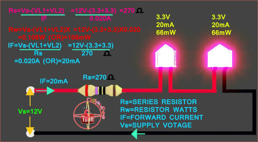
Well, as it turns out, there's only 1 LED in the 1.14" LCD and it only needs 20mA! IIRC, the 1.47" LCD required 180mA.
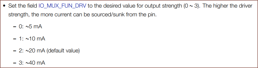
Digging into the ESP32-S3 datasheet, the current output of each pin is actually adjustable! In the MINI datasheet, it says that 40mA can be sourced and 28mA can be sunk from a GPIO.
The real question is if I can use those UART pins at all. Looking at the MINI schematic, it already looks like I can only use RX for backlighting since TX has an almost-500 ohm resistor on it.
Using the below equation I found on the internet, I believe I need a 15 ohm resistor between the pin and the LED anode. Alternatively, I could always just have a maximum PWM value such that the pin maxes out at 3.0V. There's likely going to be a voltage drop anyway too.
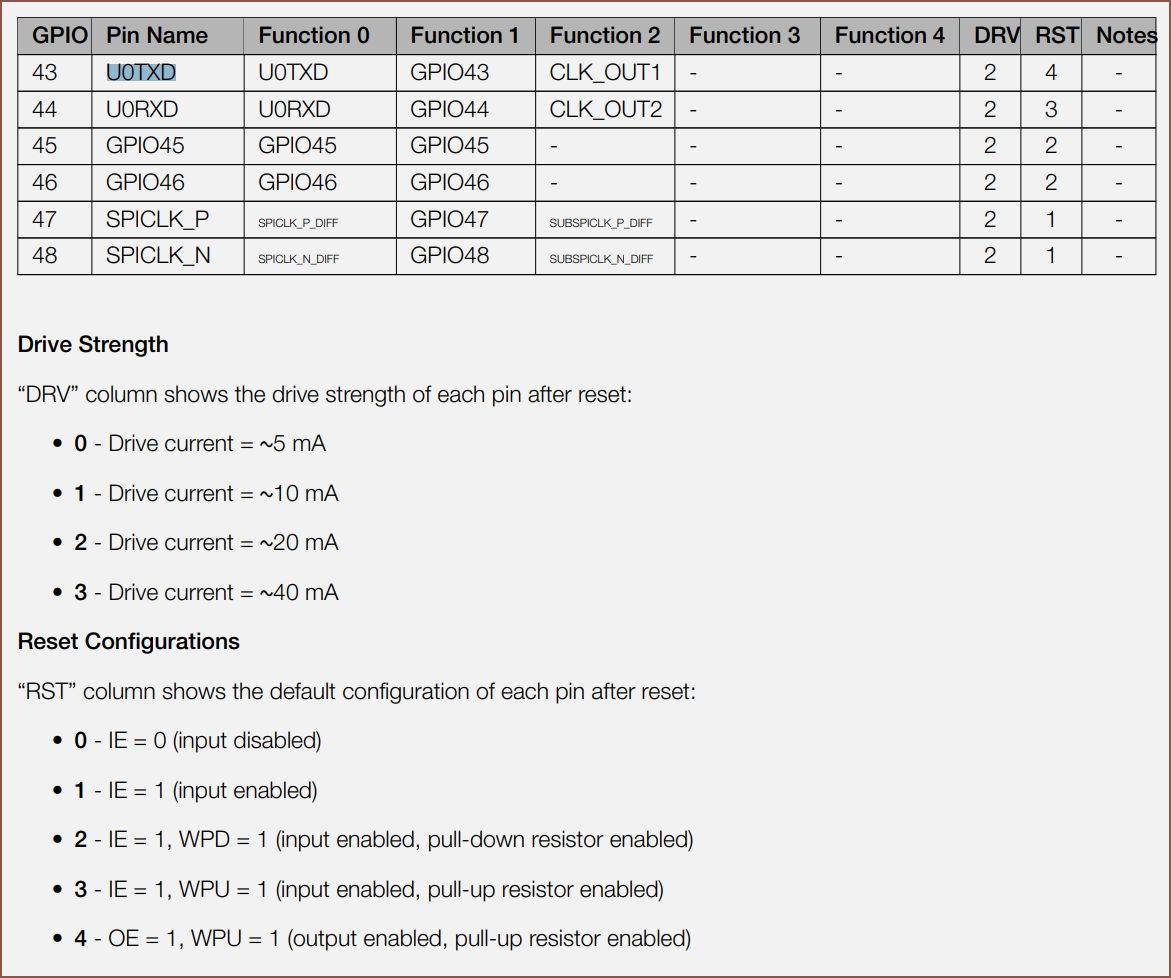
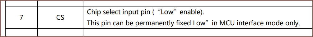
It also seems that, unlike most other pins that have reset configurations of input enabled/disabled, TX sounds like outputting a logic 1 and both have a 45kOhm pull up enabled. Looking at the LCD docs, it sounds like this is fine as it only listens on the SPI bus when the CS pin is a logic 0:
I've also looked at how it's been done on the T-Display, which is an ESP32 (not ESP32-S3) development board with a 1.14" display, and they've done the traditional transistor circuit. I guess, worst case scenario, such circuitry is added onto the pressure plate PCB that the LCDs actually connect to, since there's more space there.
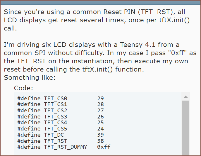
I also checked to make sure that I could use multiple LCDs on the same reset pin, and I can if I code in a dummy pin, as seen below.
In other news, I've added the same tabs as the BLDC onto the PCB. If you've seen #Coaxial Hotend [gd0144] logs, the shape may seem familiar.
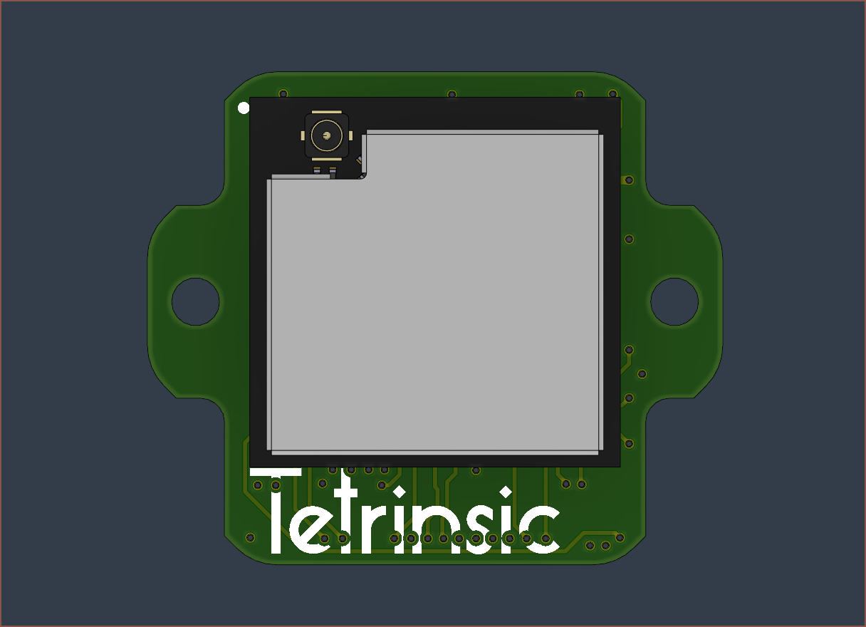
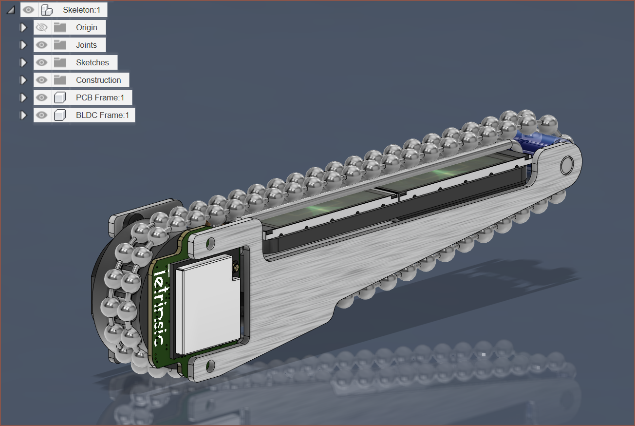
Next, I've started recreating the skeleton:
The frame cuts are 91mm, and it seems that the price break at JLCPCB is 100x100mm. I'll need to find out how big the antenna connector is so that I can ensure that I'd be able to connect it. Right now, I'm assuming that I'd be able to use the copper layer to solder the two together with brass tubing, but if not I'll just swap it so that the silkscreen is visible instead.
This log also took 110 minutes to create.
Discussions
Become a Hackaday.io Member
Create an account to leave a comment. Already have an account? Log In.