 Vini's Lab
Let's shift a bit now from the mechanics design to the electronics side.
One of the first parts I designed from the electronics was the stigmator drivers and keypad.
The reason for that is simple: it is one of the easiest parts :D
All the electronics for the SEM will be housed on a eurorack.
The cards will be split in functional blocks, so the stigmator has it's own card.
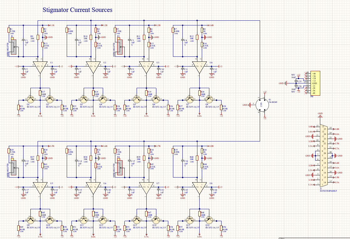

The first schematic contains the eight independent drivers capable of 500mA of current each to drive the stigmator octopole.
The reference current comes from the keypad which can be adjusted with the potentiometers P2 and P3.
The 555 generates a 0.5Hz signal that is sine waved by the low pass filter and can be selected by S2 and S3 to actuate one of the axis. The schematic is still missing the voltage reference, it only needs to have short term stability since this is an manual adjustment the operator does before imaging the sample.
The Keypad connector is the 5 Pin M12 those industrial connectors are great.
The DB25 connector goes to the SEM column and connects to the stigmator connection PCB via normal braided cable.
Discussions
Become a Hackaday.io Member
Create an account to leave a comment. Already have an account? Log In.