 Daniel Grace
I haven't been as productive as I would have liked. For reasons that aren't important to this build, I have to shift focus away from what I have been working on and go to more theoretical stuff temporarily. Given where I am in the project, that means mechanics. I said before that I had an idea on how to make that part somewhat unique. In this post I am going to attempt to explain it.
There are quite a number of variations of aluminum extrusion that are all vaguely similar.
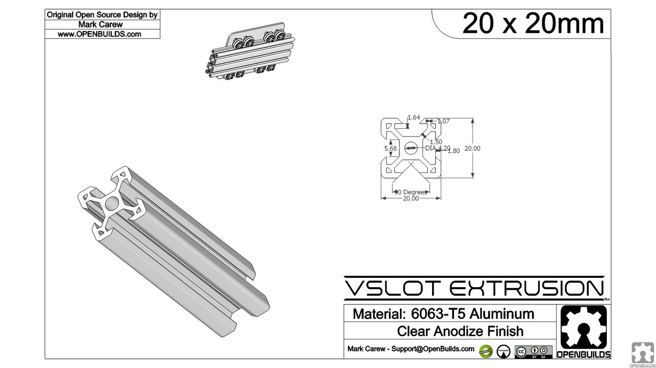
Here you can see two that are on my radar, though I am aware that many other places have their own variation. The top one is from misumi and is showing both the 30x30 and the 30x60 (which is basically two 30x30 side by side). The bottom shows a 20x20 from open builds. Both places sell variations on the size.
Here is how I hope to arrange some rails (note: this was done with open build rails because they were the easiest to get the CAD models for, not necessarily because I am going to use them):
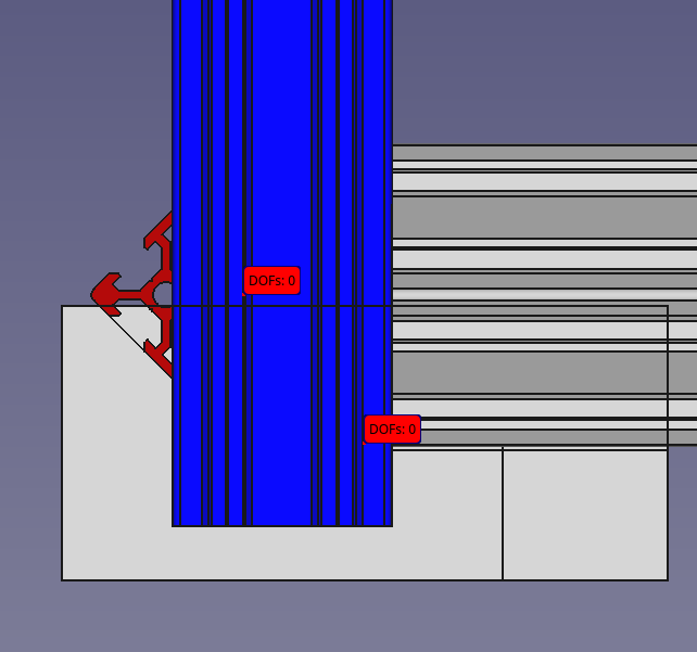
The rail in blue is the vertical support rail. It will be oriented "normally." The rail in red is at exactly 45 degrees in the image, but there is some wiggle room here (there likely will HAVE to be to make the math work). If you notice on the left side of that red rail there's what looks like a perfect slot for some acrylic paneling to go. In fact, with some open builds rail I have in hand I have tested it and it works just fine.
Right now though I have a trig problem I am trying to solve. This is going to be hard to explain for anyone who hasn't used so-called "blind joints" in extruded aluminum before (I was exposed to the idea from the Voron design, though I'm sure it's used elsewhere, too). I want to find a complementary set of rails where I can blind joint the red rail with the blue rail and the angle works out such that acrylic can comfortably fit in there. With open build rails and exactly 45 degrees, there is some wiggle room. I will need that for some weather sealing, but I can probably work with less. And if another rail design has a larger opening, that means more wiggle room on angle.
It's just a LOT of dependent numbers, and I haven't done trig in a LONG time.
(Note: ignore the silver/white parts in the above. It's from the most recent design I have done in CAD, but there are problems I want to fix.)
(Oh, and I've made progress on the reflow oven, which again is related because I will use it to help make this project, but it's not this project.)
Discussions
Become a Hackaday.io Member
Create an account to leave a comment. Already have an account? Log In.
Sounds like arccos( [width of acrylic] / [extrusion gap] )
Are you sure? yes | no
That may be one constraint, but the blind joints lining up is another. I'm doing some chores at the moment, but I'll double check that arccos did what I want once I'm back. You may have simplified the problem for me!
Are you sure? yes | no
I think that I have figured out what combination of bars work. I didn't wind up using arccos directly, but did use arcsin, and I'm pretty sure there's a form of this that does use arccos, I probably just approached it from a slightly different angle.
Are you sure? yes | no