 Sagar 001
Hello guys, today we are going to setup our 433Mhz transmitter and receiver modules with their supporting cards. We are using cheap 433mhz modules and we are not using any microcontroller with this. The dedicated encoder and decoder IC’s can do the job perfectly.
433MHZ modules:

Cheapest RF (Radio frequency) modules available in market and these are available easily on eBay, amazon. For 433MHz we need about 17.3 cm antenna for proper communication, The range is up to 100meters. Which make sense to use these modules inside homes as remote-control devices for lights, fans, tv and toys like cars.
The two types of modules are available but the Red colored one is working fine in all the applications, Also this one has a crystal oscillator which communicate directly with receiver. The second(green one) module has a coil and capacitor rasonator circuit, which I will not recommend to use in high end applications.
Wire Diagrams:
About Cirkit Designer Software:
Here is our new schematics designer tool “Cirkit Designer” which is totally free to all and is the most comprehensive breadboard layout tool.
Accordingly, I think Cirkit Designer is the best software to make breadboard schematics presentations. It also gives you the ability to view the circuit net diagram and BOM (bill of materials). This is very helpful for presenting yourself well as an electronics student or hobbyist, and the bill of materials helps to estimate project cost and procure parts.

Cirkit Designer is a one-stop-shop desktop application for designing and documenting circuits and electronics projects. With Cirkit Designer, you can lay out realistic circuit diagrams that are linked to a bill-of-materials so that you can seamlessly order the parts to your circuit.
Download cirkit designer from Here
In the next release, Cirkit Designer is adding a code IDE with full support for compiling and programming Arduino boards, as well as a library of reference circuit designs (circuit templates including documentation, components and wiring, and code). Cirkit Designer will become the one-stop-shop to help you progress from concept to fully working breadboard prototypes. Simulation will also be added in the future, so that you can test your circuit before buying parts and building anything.
Components required:
- HT12D ic
- HT12E ic
- RF 433 transmitter and receiver module
- battery (5v- recomanded)
- 1Mohm and 47K resistor
- LED's (different colors)
- Tactile switches
- Custom PCB
- Wires and breadboard
Schematics:
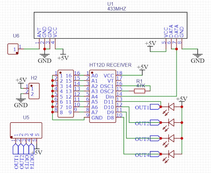
Receiver-

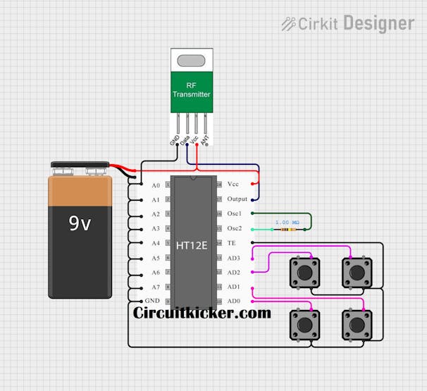
Transmitter
Circuit description:
Transmitter section- Here in diagram, We are using HT12E is used to encode the data from the button pins and then sent to receiver part by 433mhz module. So, for oscillations we are connecting 1Mohm resistance as mentioned in the datasheet of the IC. Also there is one big DIP switch, which helps to select 8 different channels. Simply meaning that we can run 8(transmitters and receivers) at one place without interference. So that’s a very good and helpful update here. We can attach four tactile buttons or something like PWM signal to the input terminals for the data to get transmit. We have to give an active low signal for triggering.
Specifications of 433MHz RF Transmitter Module: –
- · Max range with the antenna in normal Conditions: 100 Meters
- · RX Receiver Frequency: 433 MHz
- · RX Typical Sensitivity: 105 dB
- · RX Supply Current: 3.5 mA
- · RX IF Frequency: 1MHz
- · RX Operating Voltage: 5V
- · TX Frequency Range: 433.92 MHz
- · TX Supply Voltage: 3V ~ 6V
- · TX Output Power: 4 ~ 12 dB
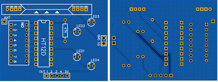
Receiver section- contains an 8-pin big module and here we are using HT12D, decoder IC. The transmitted data is received by module and then decoded by HT12D decoder. Here for oscillations we are using a 47k resistance and both the modules are supplied using 5v. We get the data in the format of active low signal. The amplitude of received data is too low, So a transistor or motor driver can be used to get the better output from this. Surely for now, we are using 5mm led’s to show the received data.5 pins on the circuit is to get the output and to connect it with a proper driver circuit.

Specifications of 433MHz RF Receiver Module:
- · Max range with the antenna in normal Conditions: 100 Meters
- · RX Receiver Frequency: 433 MHz
- · RX Typical Sensitivity: 105 dB
- · RX Supply Current: 3.5 mA
- · RX IF Frequency: 1MHz
- · RX Operating Voltage: 5V
As a driver, we can use transistor in switching mode, for digital signals. And motor drivers like, l293d and l298n.
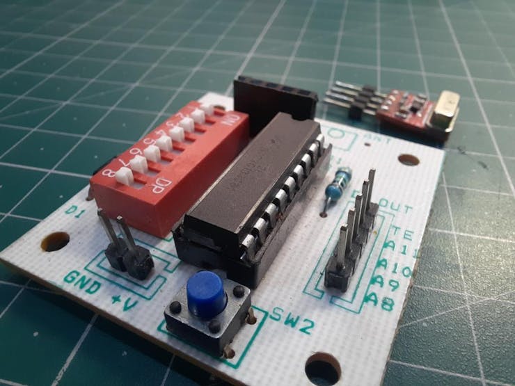
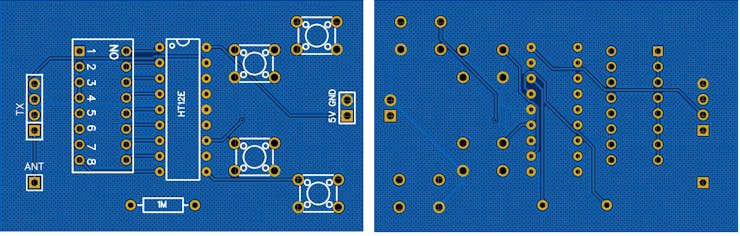
PCB designs:
Download all the Files, Gerber and circuit diagram PDF from HERE.
Decoder and encoders:
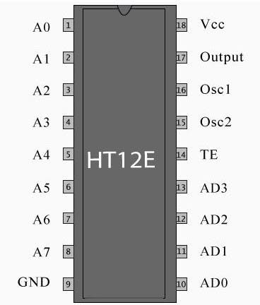
Encoder- The HT12E Encoder ICs are series of CMOS LSIs for Remote Control system applications. They are capable of Encoding 12 bit of information which consists of 8 address bits and 4 data bits. Each address and data input is externally programmable or fed in using switches.
Specs:
- 18-pin DIP
- Operating Voltage : 2.4V ~ 12V
- Low Power and High Noise Immunity, CMOS Technology
- Low Standby Current : 0.1uA (typ.) at VDD=5V
- Minimum Transmission Word = 4
- Built-in Oscillator needs only 5% Resistor
- Data code has positive polarity
- Easy Interface with and RF or an Infrared transmission medium
- Secure and robust protocol
- Ideal for remote control and security applications
- Compatible with the HT12D decoder IC
- Minimal External Components
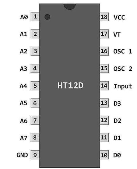
Decoder-
The HT12D Decoder ICs are series of CMOS LSIs for Remote Control system applications. These ICs are paired with each other. For proper operation a pair of encoder/decoder with the same number of address and data format should be selected (HT12E is paired with HT12D). The Decoder receive the serial address and data, transmitted by a carrier using an RF transmission medium and gives output to the output pins after processing the data.
Specs:
- 18-pin DIP
- Operating Voltage : 2.4V ~ 12.0V
- Low Power and High Noise Immunity, CMOS Technology
- Low Stand by Current : 0.1uA (typ.) at VDD=5V
- Capable of Decoding 12 bits of Information
- 8 ~ 12 Address Pins and 0 ~ 4 Data Pins
- Received Data are checked 3 times
- Built in Oscillator needs only 5% resistor
- VT goes high during a valid transmission
- Easy Interface with an RF or an Infrared transmission medium
- Secure and robust protocol
- Ideal for remote control and security applications
- Compatible with the HT12E encoder IC
- Minimal External Components
Working:
About JLCPCB:
JLCPCB is the one of the most popular PCB makers. Price is just $2 for 2, 4 and 6 layer PCB. They just launched new purple solder mask, aluminum Pcb and 3d printing service in very low cost. Pcb quality is not compromised at any cost. Check them out right now from Here.

JLCPCB Is also providing new user coupons and sign-up rewards of up to $30. So, check them out from here. Register using this link to get Free PCB assembly service coupons. Get your 2 layer to 6-layer PCB’s just in $2, stencil and PCB assembly service in just $7.
For PC: https://jlcpcb.com/SSRFor mobile phone: http://m.jlcpcb.com/ssi

Updates:
For now we are only receiving signals to drive motors, fans and relays. But they support data communication, text massages also, which we will gonna try in the next tutorial. We will also look on the more applications in future like:
- Wireless Security Systems
- Burglar Alarm Systems
- Smoke Alarm Systems
- Fire Alarm Systems
- Car Security / Alarm Systems
- Garage Door Controllers
- Car Door Controllers
- Cordless Telephone Systems
- Automation Systems
- Sensor Reporting Systems
- Remote Keyless Entry
More projects:
1) How to make Arduino Uno clone board.
2) How to program Arduino Using Smart Phone.
3) Arduino Nano clone board problems and solutions.
4) How to make Inductance Meter Using Arduino.
5) Raspberry Pi- PICO Oscilloscope.
Think you enjoy my work, stay tuned. Follow us on Instagram (sagar_saini_7294) and hackaday.
please support us- No donations, just follow and leave a comment.