 Nate Rivard
Overview
In keeping with our theme of understanding the control register, we will look at the device selection and device port subsystem.
In SPI systems, the orchestrator and many peripherals share some common lines (MOSI, MISO, CLK) so there needs to be some mechanism to signal which peripheral is the intended target of communication. In our control register, we have 2 bits dedicated to selecting 1 of 4 devices, SEL0 and SEL1:
| SEL1...SEL0 | Selected Device |
|---|---|
| 00 | 0 |
| 01 | 1 |
| 10 | 2 |
| 11 | 3 |
We also have one bit in our control register to turn off all devices. When DEN is HIGH, the device targeted in SEL1 and SEL0 is asserted and when DEN is LOW all devices are de-asserted. In other words, no peripheral should be listening anymore.
Design Considerations
This subsystem is fairly straightforward, but we still need it to:
- select 1 of 4 possible devices via software
- be able to completely de-assert all the devices or assert a single device via software
- have some mechanism to connect devices to this circuit
Design
We will start by selecting 1 of 4 possible devices. We have already looked at using a 2-to-4 mux in our clock select circuit. This device takes 4 input lines and selects 1 of those lines as output via 2 select lines. Our device select logic, though, should actually be the opposite: we have a single "input" (we will discuss this later) that we want output on a single line out of a possible 4 lines. To accomplish this, we will use one half of a 74HC139 Dual 2-to-4 line decoder/demultiplexer (don't worry that the diagram states a 74LS139, it's being used here because it has the same footprint and function).
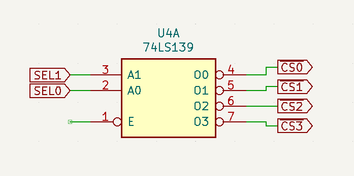
You may have noticed the deliberate usage of "assert" and "de-assert" when referring to turning on or off a device. This is because SPI is active-low to assert a device, not active-high. That means for our demux, our input would actually be a constant LOW signal and that LOW would flow out to the selected device. One nice feature of the '139 is that "input" is already assumed.
We also need a way of de-asserting all devices. In other words, we want all of the outputs to be HIGH. Another feature of the '139 is that it has an active-low ENABLE pin. When E is HIGH, all the outputs are HIGH. When E is LOW, the line selected via A0 and A1 is LOW.
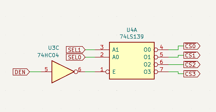
The intended method of controlling this is to use DEN. One consideration here is that on bootup, RES will go low and we want our control register to be reset. The 74HC273 we're using will zero the itself out, which means a LOW signal will be the default for DEN.
If we connect that line straight to E on our '139, it means a device (in this case Device 0 bc SEL0 and SEL1 will also be reset as LOW) will be asserted! This could be very bad as we don't know what will be on some of our other lines like CLK, MOSI or MOSI. So ideally, we want a LOW on DEN to mean de-asserted and a HIGH to mean asserted.
To do this, we will use one-sixth of a 74HC04 Hex-inverter. So our final design for the device selection logic is:
Lastly, we need a way to route our signals to actual devices. A simple and flexible way to do this is to provide a user port on the board. We haven't talked about some of the signals referenced in this circuit, but here is our port:
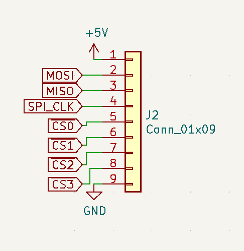
It provides 5V power and shared GND (only GND is truly necessary here. Devices can be self powered if they want to), MOSI, MISO, and SPI_CLK (these will be discussed when we talk about the data register) and our 4 device select lines.
One interesting and perhaps nice change would be to provide 4 almost identical ports:
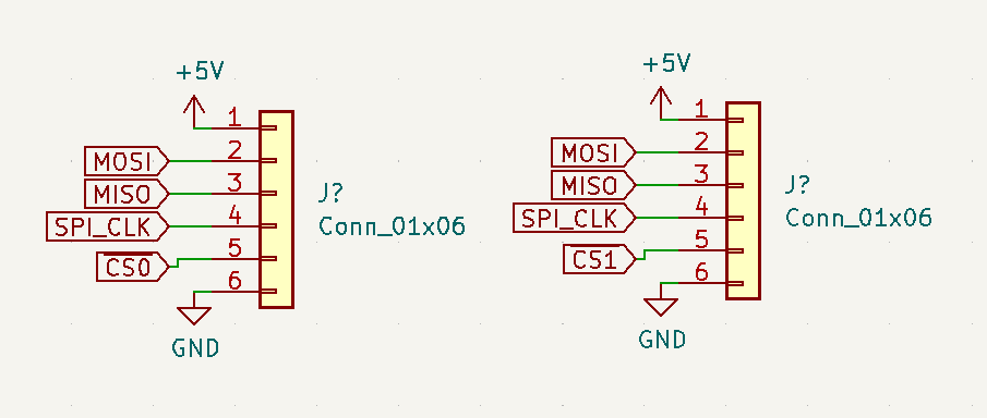
Here our shared lines are in identical spots across two ports but they each have a separate device select line routed. This would allow us to standardize connectors for our devices and provide power and ground to each device.
But for now, we will go with a single 1x9 port!
Discussions
Become a Hackaday.io Member
Create an account to leave a comment. Already have an account? Log In.