 8bitflynn
Finished with clock.
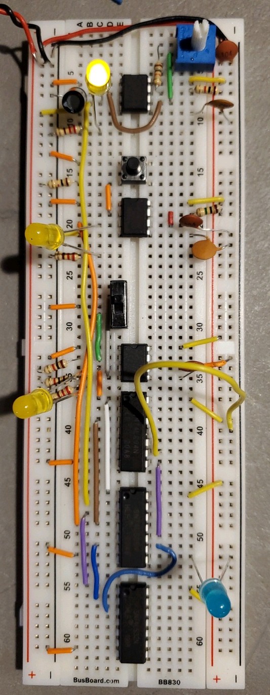
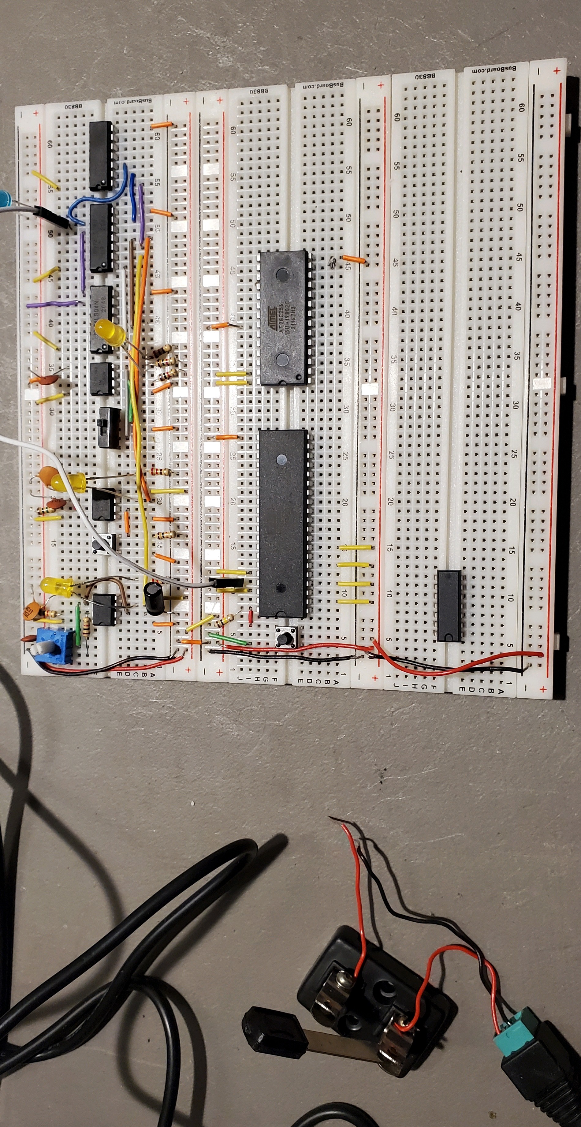
Started on 6502 breadboard computer.
Hooked up LEDs to address pins and then to Audrino to monitor. Only wired first five address pins so far. I think making a map of the mnemonics of the address and data lines would be useful to print in the serial monitor...
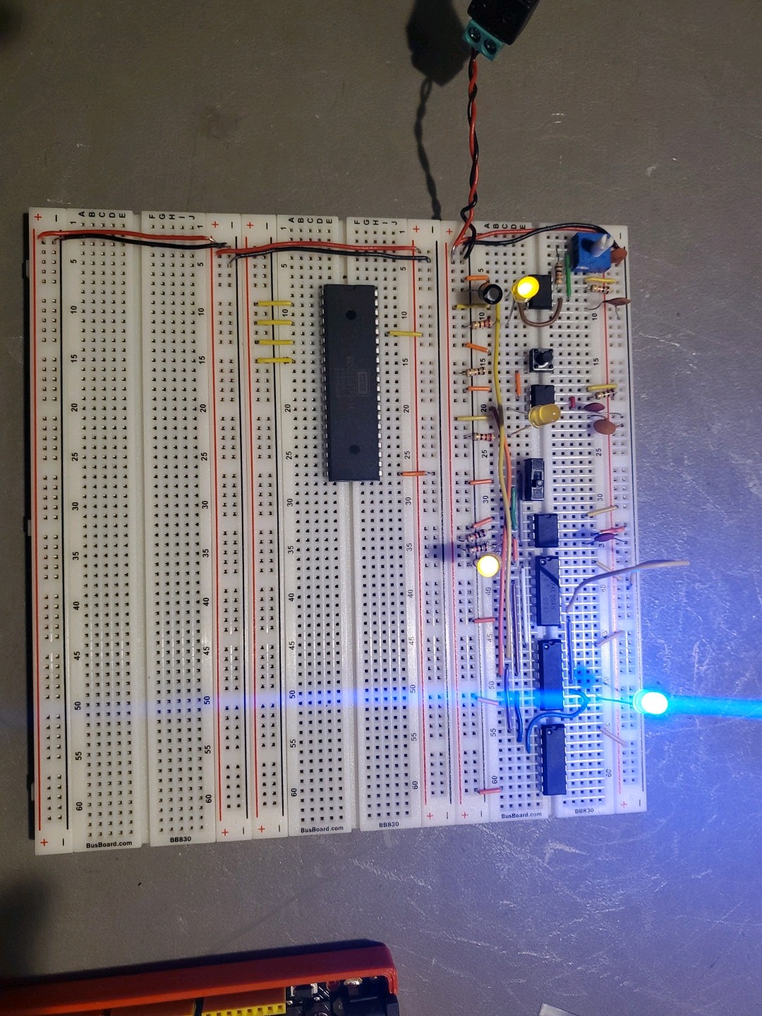
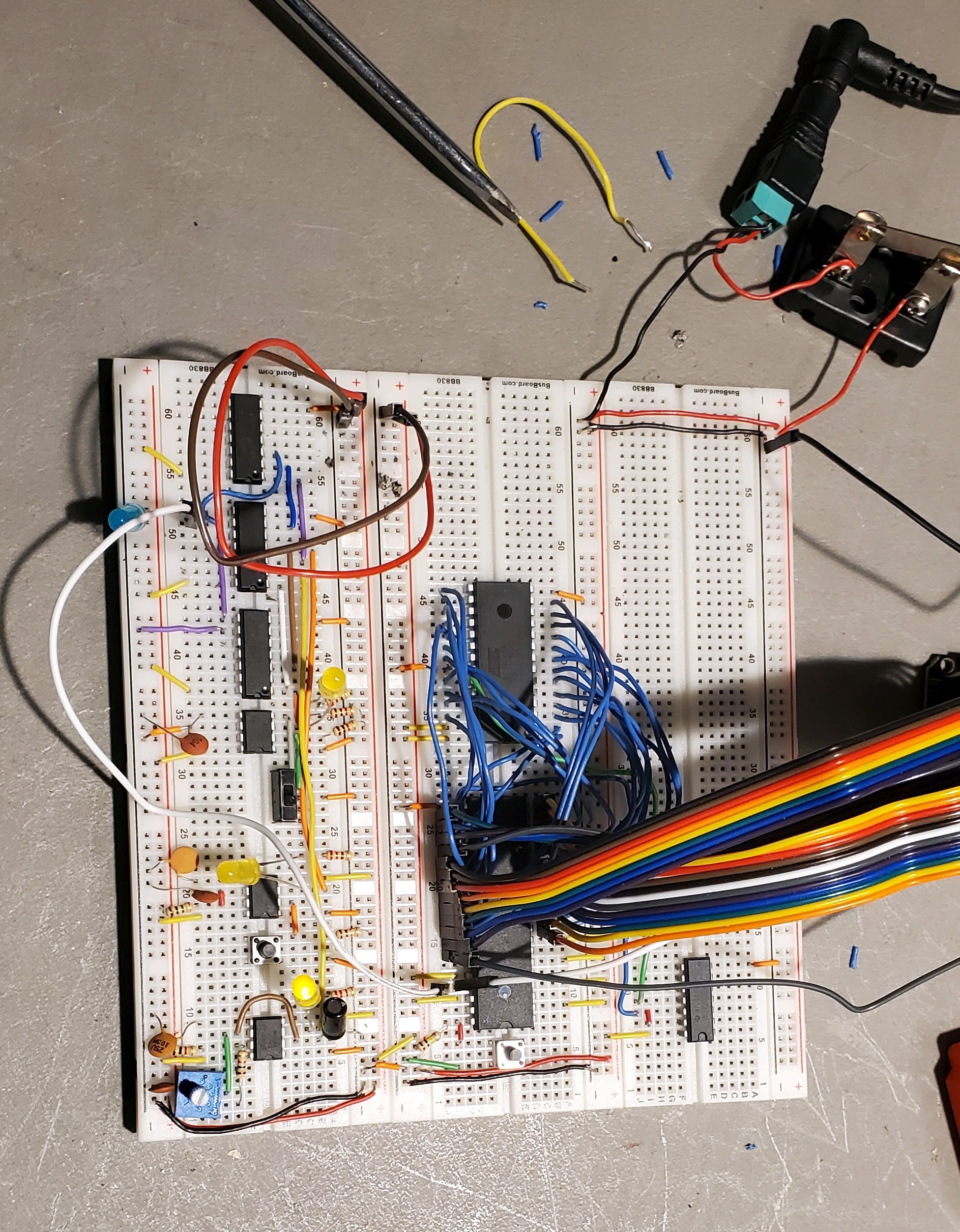
Finished hooking up address and data pins to Audrino and then the R/W pin.
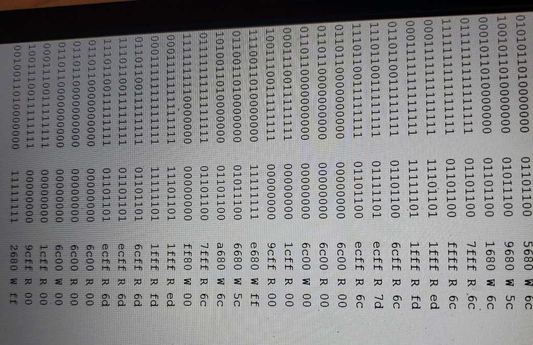
Serial monitor printing address pins and data pins first in binary and then in hexadecimal. The Read/Write pin also shows if the data pins are reading or writing.
Removed address LEDs and added EPROM chip. Installed EPROM programmer software and tested. Next up is to hook the address and data pins from the 6502 to the AT28C256 EPROM chip. The EPROM chip is 32KB so it has 15 address pins while the 6502 has 16 address pins and can access 64KB. Also the 6502 startup sequence looks for 0xfffc and 0xfffd to set the program counter to execute code. To make that work the EPROM needs to only to accessible by the 6502 address lines if the last address line not in use is connected to the EPROM's CE (chip enable pin) so that 0x0000 - 0x7fff is not used for EPROM but if last address pin on the 6502 is on, it triggers the CE on the EPROM and data can be read.
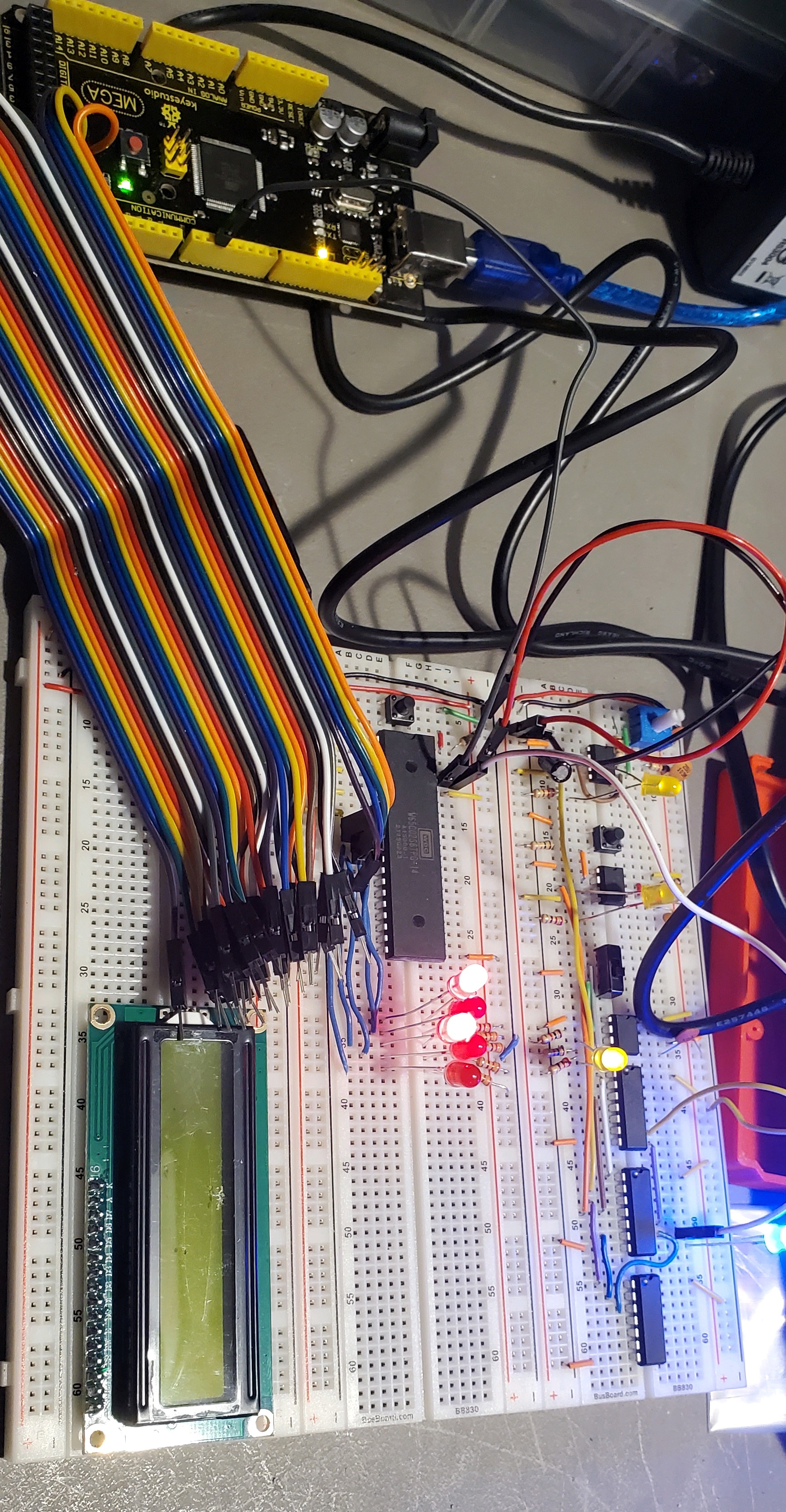
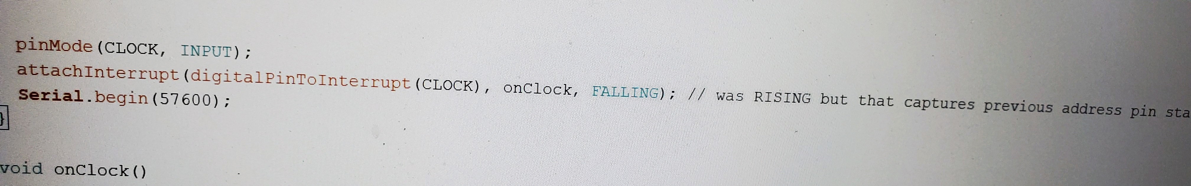
I slightly modified the Audrino code to signal the interrupt when pin 2 is falling rather than rising because from my testing with the red LEDs I was always seeing the bits in the serial monitor from the previous CPU cycle. I am guessing that having it trigger the interrupt on the clocks high signal was causing it to sample the address limes before the 6510 had changed the address lines. Setting the interrupt to happen when the clock signal is falling made the red LEDs match what the serial monitor.
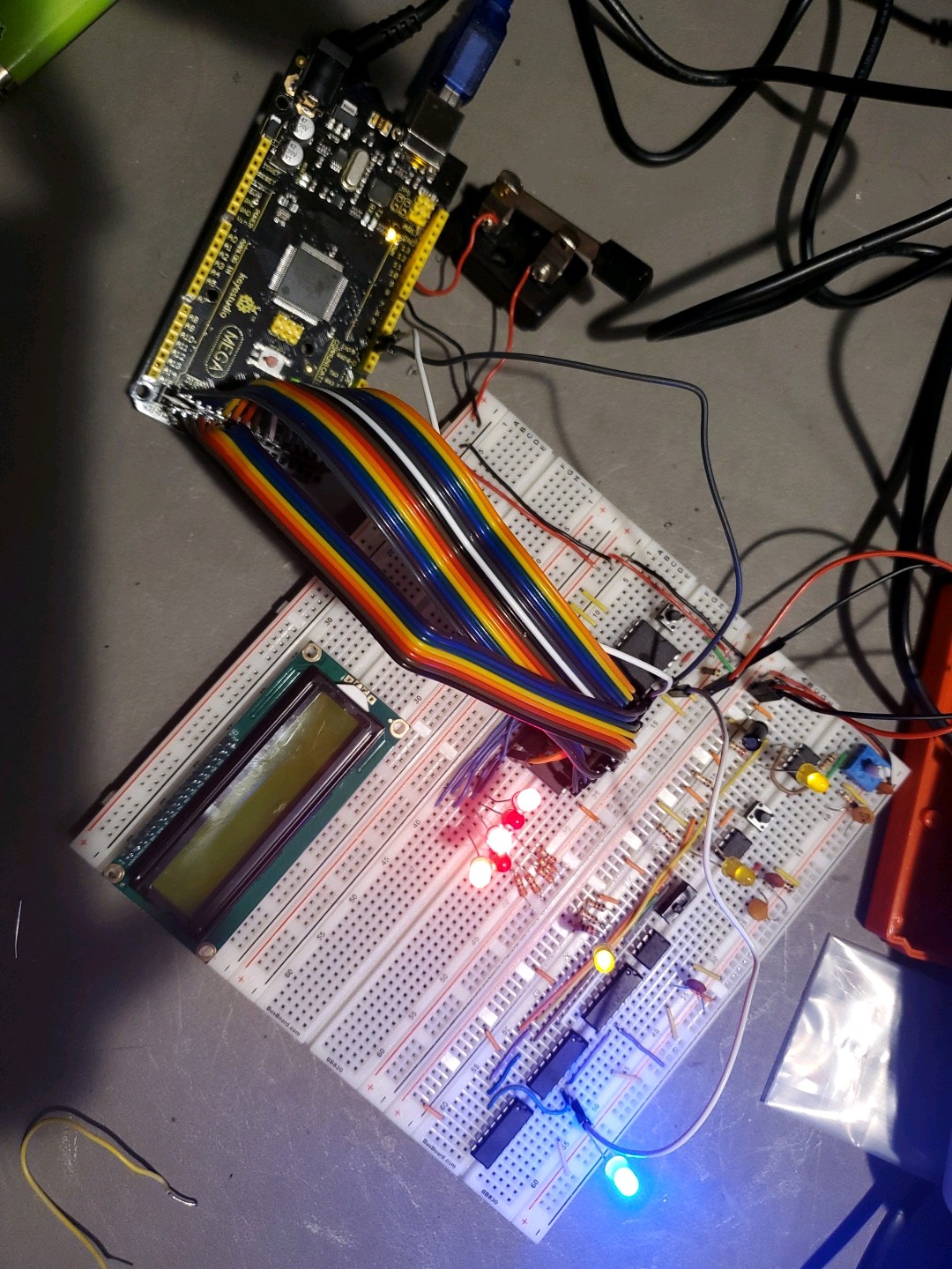
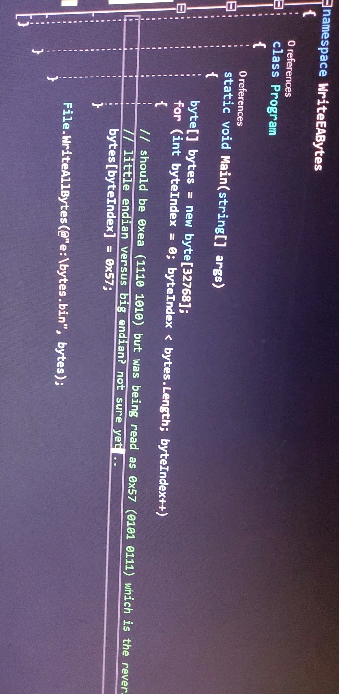
Hooked up EPROM a week ago. wrote a C# program to create the 0xea bytes but serial monitor was showing CPU data pins reading 0x57 which is the opposite bit pattern.
Changed C# program to create 0x57 bytes instead of 0xea bytes. I am going to install Python and try creating the binary the way Ben did it. It could also be I hardwired the data lines in reverse but I rewired and checked several times.
Now that i know the CPU is reading from the EPROM, I will need to run some more tests to hopefully figure out why I had to reverse the bits on the binary on the EPROM to get the correct value in serial monitor.
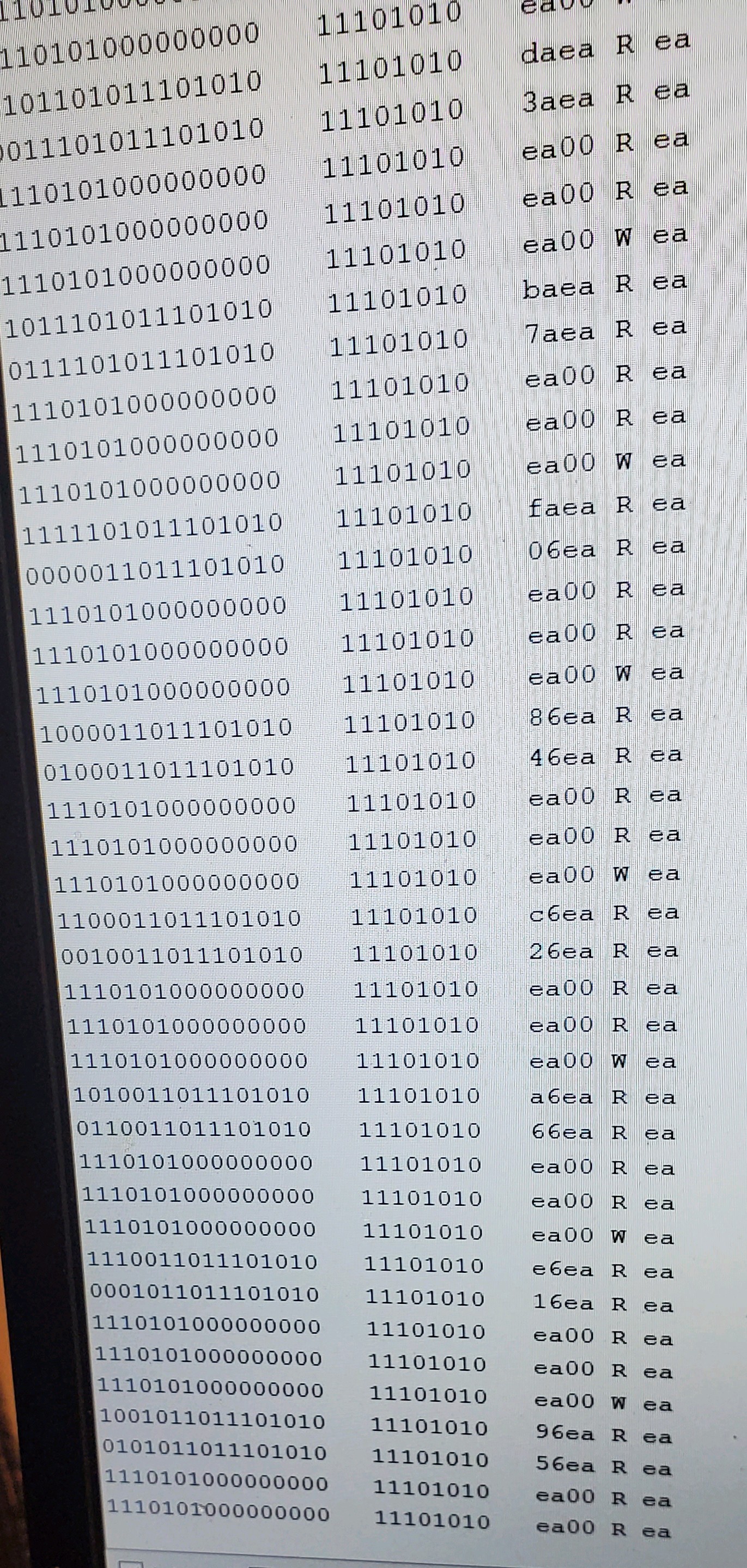
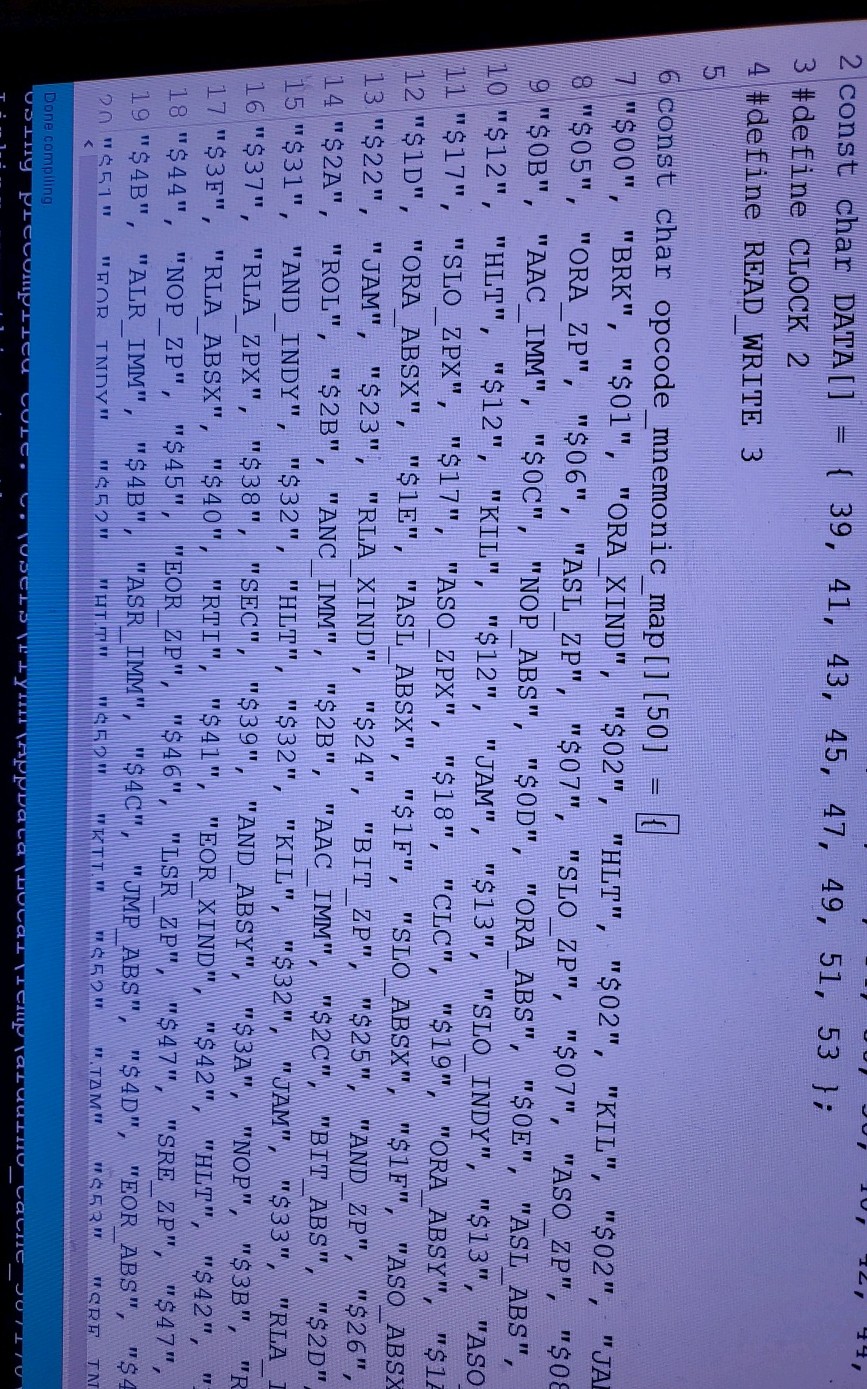
Added in a opcode to mnemonic lookup to audrino sketch so serial monitor can show the mnemonics as its capturing the data pins each clock cycle.
Discussions
Become a Hackaday.io Member
Create an account to leave a comment. Already have an account? Log In.