 Bud Bennett
[Edit 2022-06-10: updated Current State of Progress.]
[Edit 2022-04-21: added a section describing the code flowchart and updated the project status.]
I have a timer cube -- from Amazon -- that will timeout 4 intervals: 1, 5, 10, 15 minutes. You simply tip the cube from the "off" side to one of the labeled intervals and it begins to timeout the interval. When it's done it beeps for about one minute, or until you flip it back to the side that designates "off". There is not much to it...no menus...just an on/off switch (which seems unnecessary.) The cube uses a metal ball (I'm guessing here) that rolls to the lowest point and informs the intelligent circuits which side is downward so that it can time out the interval properly. There is also a 4-digit LCD display that I almost never look at. I use this timer cube most often to let me know when to let Lucy, our Border Collie mix dog, back into the house after a potty break.
I thought it would be a nice simple project to employ some electronic hardware & software, as well as improve my 3D printing expertise, which is in its infancy.
Functionality:
- It should be low power since it will have a relatively small battery for power. I'm shooting for an idle current of less than 25uA, and less than 3mA average current when timing an interval. There is no on/off switch.
- It should begin a timing interval after having it's 3-dimensional position changed. There are seven timing intervals (3, 5, 10, 15, 30, 45 and 60 minutes) and an off state.
- The timing interval can be terminated simply by setting the box in the off position. In addition, any timing interval can be changed to another and restarted by tipping the box to a different side.
- The box will emit a short beep/tone/annunciation to confirm that it has started the interval.
- At the end of the timing interval the box emits 40 beeps/tones/??? until it is set to its off position or the series of beeps expires.
- The display will indicate the remaining time left in minutes:seconds. The Off position of the cube has the display face down on a surface, so that all of the timing intervals have a visible display. The display remains oriented so as to be always be "right side up" and readable.
- Power is from a single lithium-Ion 10440 (AAA size) rechargeable battery. The battery should be easily replaceable. An internal charger gets 5V nominal power from a micro-USB connector. Recharging a depleted battery should require 1-2 hours, and the unit should have a standby operation of more than one year and be able to time out more than 100 hours per charge.
Other Features in the "It Would Be Nice To Have" Category:
- A menu mode to change certain parameters -- like beep volume, etc. This would be and interesting challenge since there are no buttons or switches on the box.
- Total cost < $10 USD.
I've settled upon the PIC16F18345 micro-controller: a 20-pin 8-bit part that seems to contain the kitchen sink of stuff that you might need: I2C interface, ADC, PWM for beeper, low current secondary 32768Hz oscillator, timer/counters, 14k of program memory -- all for about $1.5 in low quantities. Here is my current schematic (currently rev.2):
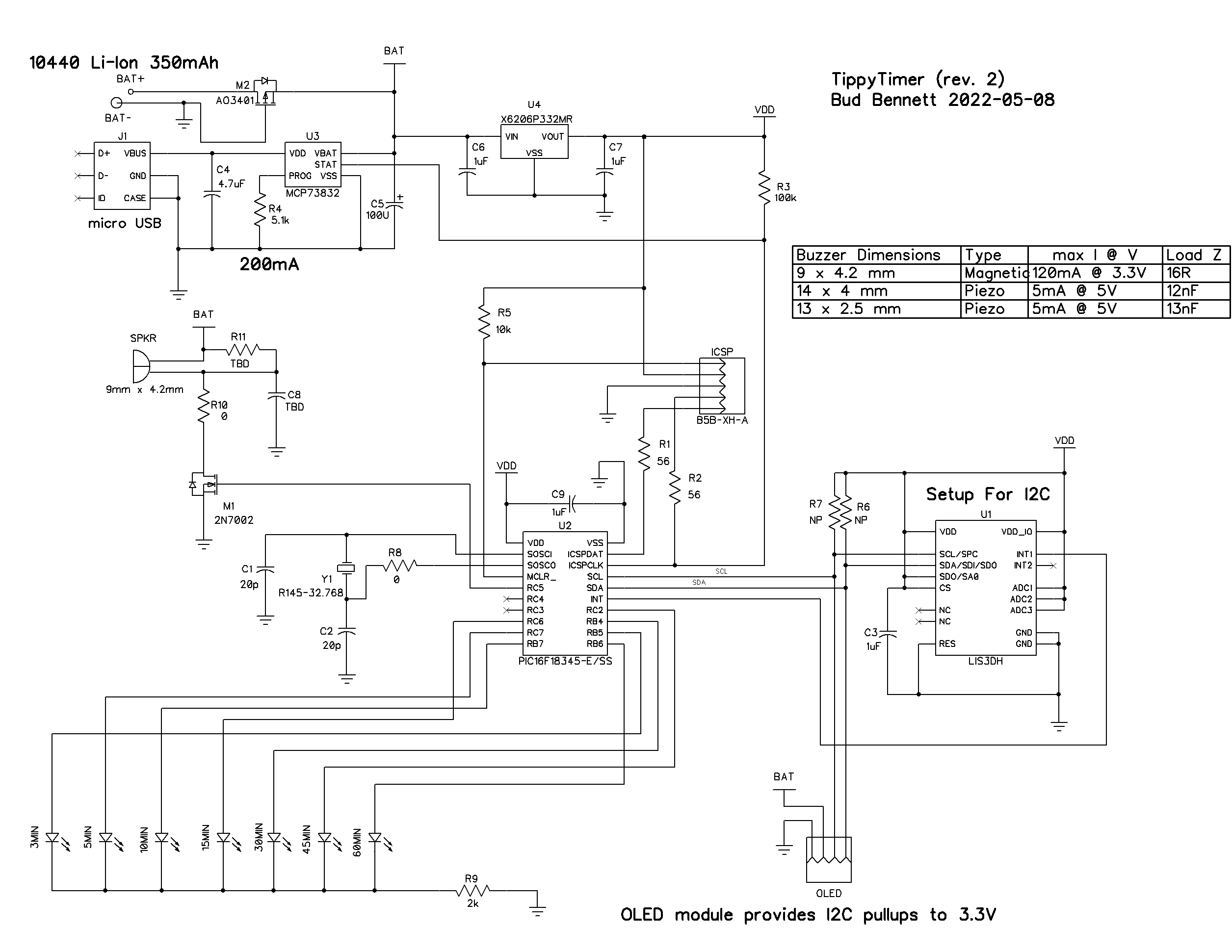
This design uses one AAA 3.7V Li-Ion battery. I have figured out a method to house/contain this battery. I initially intended to use LiPo chemistry, but the system uses a 3.3V regulated voltage for VDD. The PIC's ADC is setup to measure an internal 2.048V input voltage using VDD as the reference. This implies that the PIC won't know what the battery voltage is until it drops below 3.3V. LiPo batteries should not be discharged below 3.5V, hence the switch to Li-Ion since they can be discharged to 2.5V without damage. (Yes, I could have configured the ADC to use an external resistor divider from the battery, but this is more PIC pins, components and potentially more current.)
Instead of a rolling metal ball, I'm using an accelerometer IC -- the LIS3DH -- which is a cheap and low current IC to tell the system what the orientation is.
The display is a 128x32 OLED module that is cheap at about $1.5/each, but should do all that is needed. The OLED module has an efficient on-board 3.3V regulator, so I connected the OLED power pin directly to the battery to offload the OLED current from the system LDO regulator.
The speaker, a 12mm piezo buzzer type, is connected to the battery voltage and driven by an ubiquitous discrete 2N7002, to offload that current from the system LDO. The speaker will need some sort of hole in the box...TBD.
The seven LED indicators are mounted on the associated faces. The LED is on for one second every two seconds. They inform the user that the timer is active without looking at the OLED display. They don't draw much current, so they're driven directly by the PIC.
The accelerometer and the OLED communicate via I2C, which is a PITA. The PIC must use an internal 1MHz oscillator (250kHz system clock) in order to yield a 62.5kHz clock rate for the I2C. It's even slower with all the clock stretching. This will lead to relatively long communications, 50ms, to feed the OLED display with data. Both the LIS3DH and the OLED claim compatibility with the 400kHz I2C protocol, but the PIC would have to run 6X faster and consume more current.
Current Budget:
Sleep Current -- 22uA-27uA
- PIC during sleep -- 13.5uA (measured, shouldn't be this high)
- OLED off -- 3-8uA (measured)
- LIS3DH (low power mode, 25Hz data rate)-- 4uA
- XC6206 VSS current -- 1uA
Running Current -- 4.5mA
- PIC duty cycle average estimated at 25ms/1sec. Supply current when clocked at 1MHz = 400uA. Running current ~ 400uA * 0.025 = 10uA (+ sleep current = 35uA.)
- OLED running current averages 4mA. I haven't yet found a way to decrease brightness.
- Side indicator LED current ~ 325uA
If the battery is truly 350mAh, then the TippyTimer will be able to operate in standby for nearly 1.5 years, and timeout 75hrs before needing a recharge
The Code:
Pretty much starting from scratch with a todo list:
- Configure PIC
- Generate interrupt routines.
- Generate I2C read/write routines.
- Test out communication with Accelerometer and OLED.
- Configure Accelerometer to detect position movement.
- Configure OLED and test.
- Write data to OLED and test.
- Generate flow chart and implement main code.
All of the above is done using PIC assembler, since I refuse to learn to program in C. I have about 1600 lines of code so far - 38% of the total code available in the PIC. Here's the flowchart that I'm using for the main code loop:
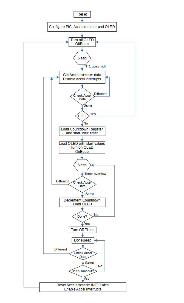
I'm not a big fan of interrupts, so there is only one interrupt enabled at any time. The accelerometer can be configured to output an interrupt on its INT1 pin when there is a change in movement. The INT1 pin is set to latch high when an interrupt occurs. It is not reset until the main loop is done and the timer is in a sleep/off state.
To minimize current draw the PIC is in sleep mode most of the time. It comes out of sleep to update the countdown timer and the OLED display, check if the countdown is finished and goes back to sleep. This normally takes about 20-50ms, depending upon how many digits need to be updated in the OLED, but 90% of the time it only requires 20ms to update just the 1-second digit of the OLED.
The user can change&restart or terminate the countdown at any time. When the countdown is finished the timer is turned off and its interrupt is disabled. It then enters a loop where it generates a unique DoneBeep while checking to see if the user has changed the position of the box to either start a new countdown or set the box to the off position. If nothing changes the loop eventually times out and goes back to a sleep state -- waiting for an interrupt from the accelerometer.
Current State of Progress:
I have a working second-pass prototype!
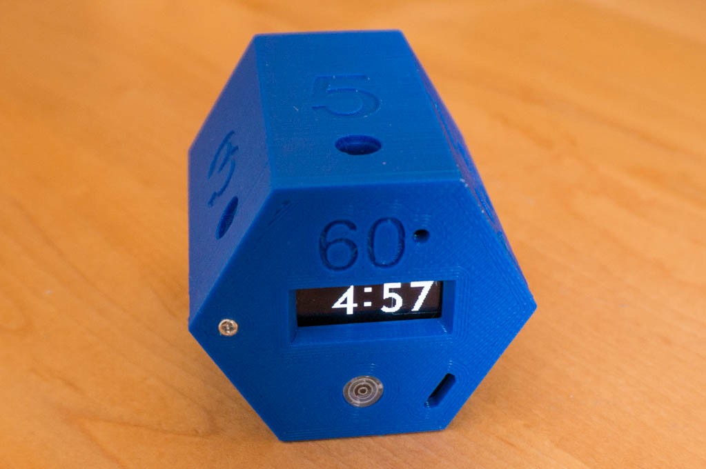
Functionally, it is 99% there. The unit turns off when set on its back (Z = 1g) and the display is blanked. It beeps and starts timing when quickly flipped onto one of the hexagonal sides, and it beeps and restarts the timing interval when flipped to a different side. The series of beeps after the timer terminates begin softly and increase to full volume (50% duty cycle) by the end of the series. The OLED displays "LOWBAT" if the battery voltage drops below 3.0V. It also displays a flashing "CHARGE" when 5V is connected to the USB connector. I still need to finalize the beeper tones/tunes/whatever and the low battery and charging indicators.
I received second-pass PCBs. They are fully functional.
Still working on the design of the case. The battery now fits nicely, without too much force from the negative terminal spring clip. The openings align better with the USB charging port, and the OLED bezel is smaller so it is easier to read at higher angles. Thinking about laser burning the numerals to make them standout better.