 Bud Bennett
The schematic and layout are pretty firm. There were a few iterations back and forth to optimize the layout. The PCB has to integrate nicely with the enclosure so a few major decisions were made.
Battery Holder Mechanics:
I did not want to use a battery holder, though they're pretty cheap. The extra space for a commercial battery holder would be just wasted. I searched for spring clips to build my own battery holder and eventually settled on these, from AliExpress:
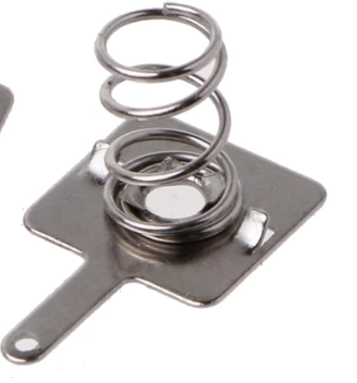
They are 9mm x 10mm x 6mm high, and about $0.16/pair. They come as a +/- pair, but I don't think I'll need the positive terminal -- the battery positive button will just contact a soldered pad on the PCB. I'll probably just hot glue this piece to the bottom of the battery holder and solder a wire between the tab and the PCB. That will be the only wire connection to the PCB. To replace the battery, the user will have to remove the top cover and the screws holding the PCB to the case. The battery will then just pop out. There is protection for reverse battery, so no harm if the user replaces the battery backward.
PCB Layout:
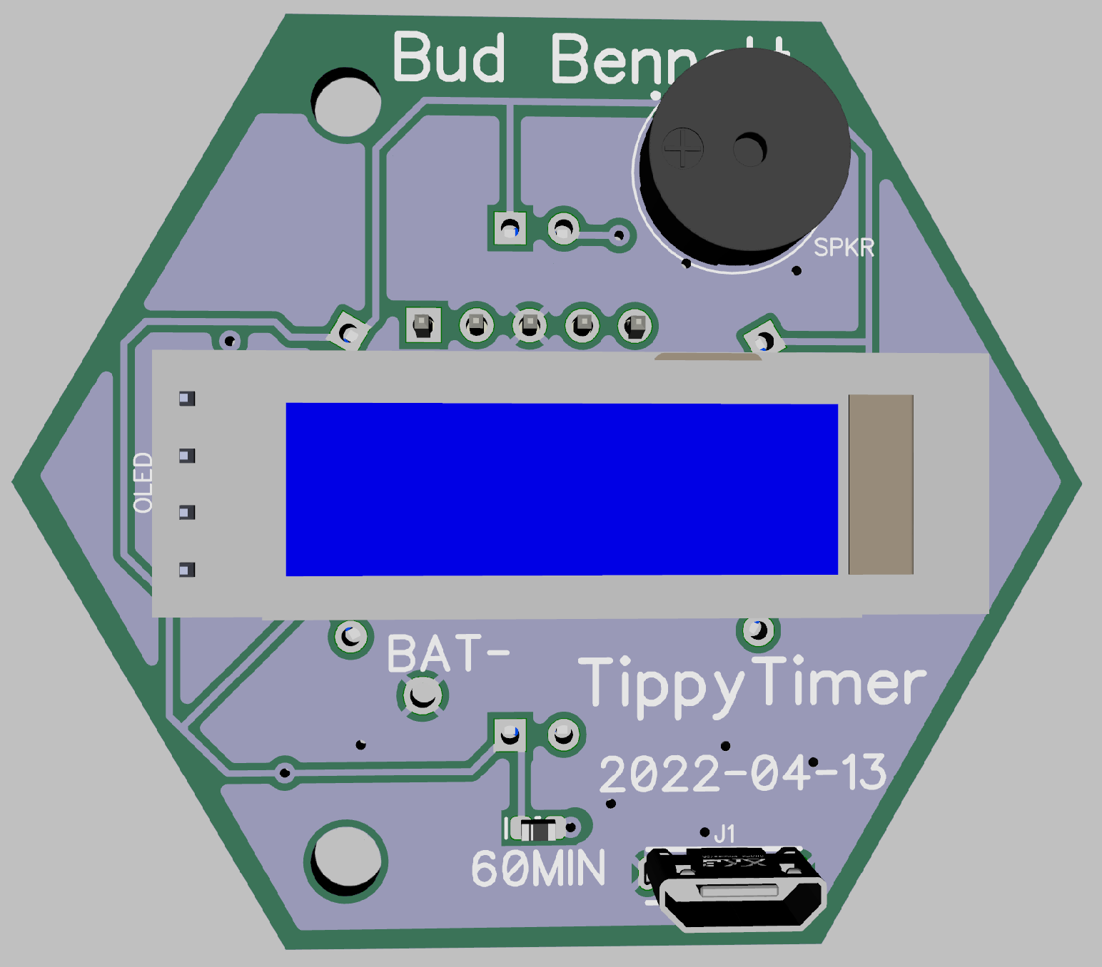
There are 7 LEDs that serve as activity confirmation. They should light up a spot on the face of the enclosure corresponding to the timing interval. This complicates the layout. I'm doubtful that surface mount LEDs could provide enough directional light, so 3mm through-hole LEDs are used instead. The LEDs will be mounted at right angles to the PCB and probably secured with hot-melt glue. This is what the top side of the PCB looks like today:

Since the LEDs will be mounted at right angles there must be nothing between the leads and the edge of the board. I measured the length from the holes to the top of the LED to be roughly 7mm and added another 3mm to clear any support shelf in the enclosure -- so all of the LED are 10mm from the respective PCB edge.
You can see where the positive terminal of the battery will butt up into the PCB. There is plenty of clearance to avoid any mishap with short circuits during assembly.
The bottom side of the PCB has very few components -- just the speaker, the OLED display, the USB charging port, and the SMD LED for the 60 minute interval. This side faces the top of the enclosure. When the timer is running the display will be visible either from the side (for the 3,5,10,15,30,45 minute intervals) or from the top (for the 60 minute interval.) When the unit is "Off" this side will face down toward the surface it rests upon.
All of the components on this side should be about the same height. The OLED is about 4-5 mm thick, the speaker is a 9042 passive buzzer that is 4.2mm high, and the vertical USB connector is 5.5mm high. I might reconsider the decision to use a SMD LED because I measures the 3mm through-hole LED to have a height of about 5mm when mounted straight to the board.
The PCB measures 44mm between the parallel sides. Slightly more than that from the opposite vertices. These dimensions are about the smallest required to fit the OLED with the display centered in the face of the enclosure. The depth of the enclosure must be about 57mm to hold the 10440 battery, the PCB with its components and the enclosure lid.
Getting the Light Out:
The enclosure will be fitted with these small "windows" to allow light from the LEDs to be visible while keeping dust and dirt out of the enclosure.
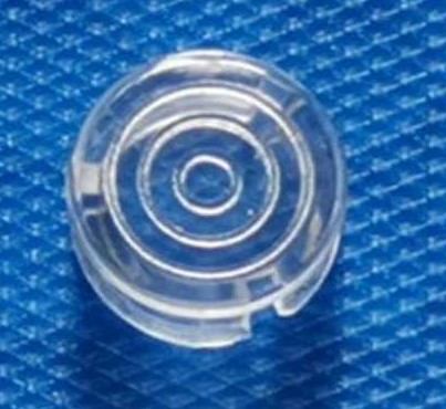
They are 6.85 mm in diameter, made for 5mm LEDs. They should just pop into holes in the 3D printed enclosure. I will need seven of these for each TippyTImer.
The Box:
I've made some progress using FreeCAD to model the enclosure. Here's a view showing the concept so far:
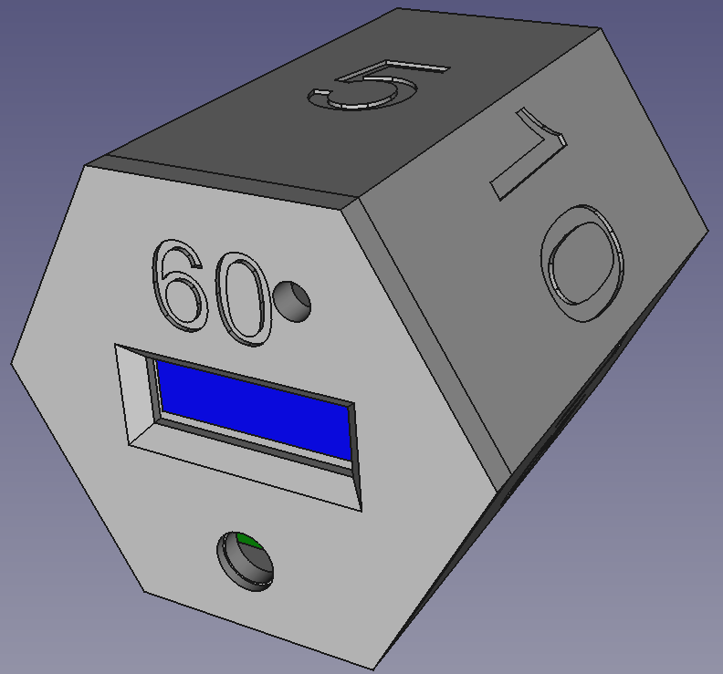
The LED " window" is at the bottom of the face with the display. I have not yet added the windows to the other faces. The hole at the top left of that face is for the speaker -- I may need to move the speaker a bit further to the outside edge to get it away from the 60 minute label. I haven't yet added access for the USB charging port, but it will be to the lower right.
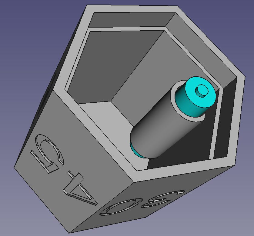
From the above view without the lid, the proposed battery holder is visible. There is also a shelf to hold the PCB. I have not yet added the supports to secure the PCB with small screws. I'm not sure that screws will be necessary if the lid can be configured to snap down onto the PCB to force it against the shelf...TBD.
The Code:
...is progressing. I will discuss that in a separate log and in the project details.
Discussions
Become a Hackaday.io Member
Create an account to leave a comment. Already have an account? Log In.